Unit VI
Special Purpose Motors
A brushless DC motor (also known as a BLDC motor or BL motor) is an electronically commuted DC motor which does not have brushes. The controller provides pulses of current to the motor windings which control the speed and torque of the synchronous motor.
Basically, BLDC are of two types, one is outer rotor motor and other is inner rotor motor. The basic difference between the two is only in designing, their working principles are same.
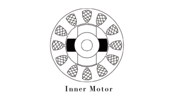
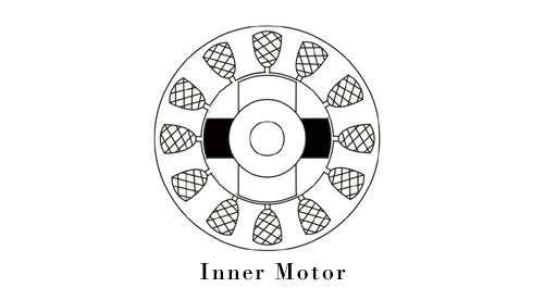
Inner Rotor Design
In an inner rotor design, the rotor is located in the centre of the motor and the stator winding surround the rotor. As the rotor is located in the core, rotor magnets do not insulate heat inside and heat get dissipated easily. Due to this reason, inner rotor designed motor produces a large amount of torque and validly used.
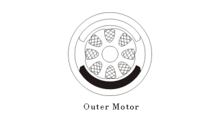
Outer Rotor Design
In outer rotor design, the rotor surrounds the winding which is located in the core of the motor. The magnets in the rotor trap the heat of the motor inside and do not allow to dissipate from the motor. Such type of designed motor operates at lower rated current and has low cogging torque.
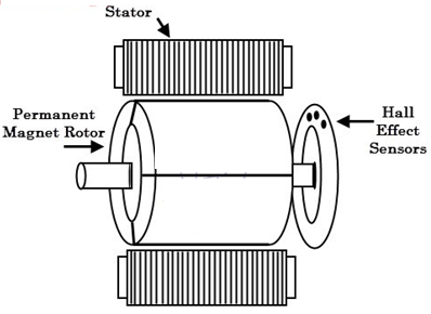
BLDC motors can be constructed in different physical configurations. Depending on the stator windings, these can be configured as single-phase, two-phase, or three-phase motors. However, three-phase BLDC motors with permanent magnet rotor are most commonly used.
The construction of this motor has many similarities of three phase induction motor as well as conventional DC motor. This motor has stator and rotor parts as like all other motors.
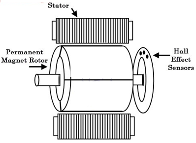
Stator of a BLDC motor made up of stacked steel laminations to carry the windings. These windings are placed in slots which are axially cut along the inner periphery of the stator. These windings can be arranged in either star or delta. However, most BLDC motors have three phase star connected stator.
Each winding is constructed with numerous interconnected coils, where one or more coils are placed in each slot. In order to form an even number of poles, each of these windings is distributed over the stator periphery.
Rotor
BLDC motor incorporates a permanent magnet in the rotor. The number of poles in the rotor can vary from 2 to 8 pole pairs with alternate south and north poles depending on the application requirement. In order to achieve maximum torque in the motor, the flux density of the material should be high. A proper magnetic material for the rotor is needed to produce required magnetic field density.
Ferrite magnets are in-expensive; however they have a low flux density for a given volume. Rare earth alloy magnets are commonly used for new designs. Some of these alloys are Samarium Cobalt (SmCo), Neodymium (Nd), and Ferrite and Boron (NdFeB). The rotor can be constructed with different core configurations such as the circular core with permanent magnet on the periphery, circular core with rectangular magnets, etc.
Hall Sensors
Hall sensor provides the information to synchronize stator armature excitation with rotor position. Since the commutation of BLDC motor is controlled electronically, the stator windings should be energized in sequence in order to rotate the motor. Before energizing a particular stator winding, acknowledgment of rotor position is necessary.
So, the Hall Effect sensor embedded in stator senses the rotor position.
Most BLDC motors incorporate three Hall sensors which are embedded into the stator.
Each sensor generates Low and High signals whenever the rotor poles pass near to it. The exact commutation sequence to the stator winding can be determined based on the combination of these three sensor’s responses.
Working Principle and Operation of BLDC Motor
BLDC motor works on the principle similar to that of a conventional DC motor, that is the Lorentz force law which states that whenever a current carrying conductor is placed in a magnetic field it experiences a force.
As a consequence of reaction force, the magnet will experience an equal and opposite force.
In case BLDC motor, the current carrying conductor is stationary while the permanent magnet moves.
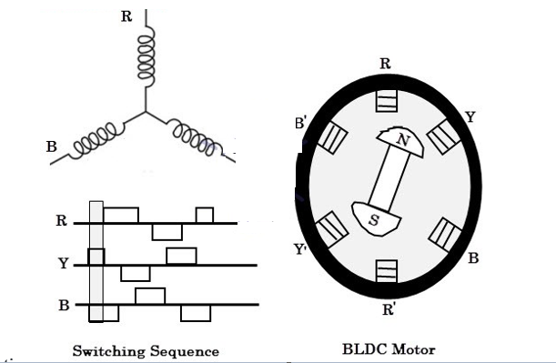
When the stator coils are electrically switched by a supply source, it becomes electromagnet and starts producing the uniform field in the air gap. Though the source of supply is DC, switching makes to generate an AC voltage waveform with trapezoidal shape.
Due to the force of interaction between electromagnet stator and permanent magnet rotor, the rotor continues to rotate.
Consider the figure below in which motor stator is excited based on different switching states. With the switching of windings as High and Low signals, corresponding winding energized as North and South poles. The permanent magnet rotor with North and South poles align with stator poles causing motor to rotate.
Observe that motor produces torque because of the development of attraction forces (when North-South or South-North alignment) and repulsion forces (when North-North or South-South alignment). By this way motor moves in a clockwise direction.

The motor continuous rotation depends on the switching sequence around the coils. The Hall sensors give shaft position feedback to the electronic controller unit.
Based on this signal from sensor, the controller decides particular coils to energize. Hall-effect sensors generate Low- and High-level signals whenever rotor poles pass near to it. These signals determine the position of the shaft.
Brushless DC Motor Drive
The electronic controller circuit energizes appropriate motor winding by turning transistor or other solid- state switches to rotate the motor continuously.
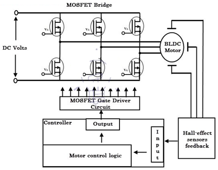
The figure shows the simple BLDC motor drive circuit which consists of MOSFET bridge (also called as inverter bridge), electronic controller, hall effect sensor and BLDC motor.
Here, Hall-effect sensors are used for position and speed feedback. The electronic controller can be a microcontroller unit or microprocessor or DSP processor or FPGA unit or any other controller. This controller receives these signals, processes them and sends the control signals to the MOSFET driver circuit.
In addition to the switching for a rated speed of the motor, additional electronic circuitry changes the motor speed based on required application.
These speed control units are generally implemented with PID controllers to have precise control.
It is also possible to produce four-quadrant operation from the motor whilst maintaining good efficiency throughout the speed variations using modern drives.
When a three-phase (brushless) motor is driven by a three-phase bridge circuit, the efficiency, which is the ratio of the mechanical output power to the electrical input power, is the highest, since in this drive an alternating current flows through each winding as an ac motor. This drive is often referred to as 'bipolar drive'. Here, 'bipolar' means that a winding is alternatively energised in the south and north poles.
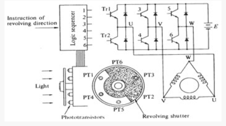
The principle of the three-phase bridge circuit of Figure. Here we use the optical method for detecting the rotor position; six phototransistors are placed on the end-plate at equal intervals. Since a shutter is coupled to the shaft, these photo elements are exposed in sequence to the light emitted from a lamp placed in the left of the figure. The problem is the relation between the ON/OFF state of the transistors and the light detecting phototransistors.
The simplest relation is set when the logic sequencer is arranged in such a way that when a phototransistor marked with a certain number is exposed to light, the transistor of the same number turns ON.
Electrical currents flow through Tr1, Tr4, and Tr5, and terminals U and W have the battery voltage, while terminal V has zero potential. In this state, a current will flow from terminal U to V, and another current from W to V as illustrated in Figure.
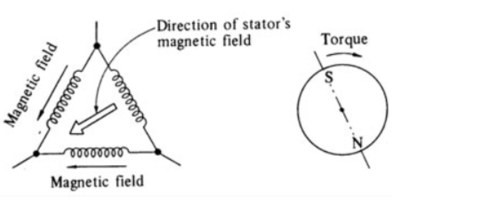
We may assume that the solid arrows in this figure indicate the directions of the magnetic fields generated by the currents in each phase. The fat arrow in the centre is the resultant magnetic field in the stator.

Three phase bipolar-driven brushless motor
The rotor is placed in such a position that the field flux will have a 90o angle with respect to the stator's magnetic field. In such a state a clockwise torque will be produced on the rotor. After it revolves through about 30o, PT5 is turned OFF and PT6 ON which makes the stator's magnetic pole revolve 60o clockwise. Thus when the rotor's south pole gets near, the stator's south pole goes away further to create a continuous clockwise rotation. The ON-OFF sequence and the rotation of the transistor are shown in figure.
Stator's magnetic field in the shutter state
The rotational direction may be reversed by arranging the logic sequencer in such a way that when a photodetector marked with a certain number is exposed to light, the transistor of the same number is turned OFF. On the other hand, when a phototransistor is not exposed to light, the transistor of the same number is turned ON.
Advantage of Brushless DC Motor
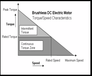
There are two torque parameters used to define a BLDC motor, peak torque (TP) and rated torque (TR).
During continuous operations, the motor can be loaded up to the rated torque. In a BLDC motor, the torque remains constant for a speed range up to the rated speed. The motor can be run up to the maximum speed, which can be up to 150% of the rated speed, but the torque starts dropping.
Applications that have frequent starts and stops and frequent reversals of rotation with load the motor, demand more torque than the rated torque.
This requirement comes for a brief period, especially when the motor starts from a standstill and during acceleration. During this period, extra torque is required to overcome the inertia of the load and the rotor itself.
The motor can deliver a higher torque, maximum up to peak torque, as long as it follows the speed torque curve.
Applications:
These are the types of applications where the load on the motor varies over a speed range. These applications may demand high-speed control accuracy and good dynamic responses. In home appliances, washers, dryers and compressors are good examples.
In automotive, fuel pump control, electronic steering control, engine control and electric vehicle control are good examples of these. In aerospace, there are a number of applications, like centrifuges, pumps, robotic arm controls, gyroscope controls and so on.
These applications may use speed feedback devices and may run in semi-closed loop or in total closed loop. These applications use advanced control algorithms, thus complicating the controller. Also, this increases the price of the complete system
There are three basic categories of stepper motors, namely
Variable Reluctance Stepper Motor
The stepper motor works on the principle that the rotor aligns in a particular position with the teeth of the excitation pole in a magnetic circuit wherein minimum reluctance path exist.
Whenever power is applied to the motor and by exciting a particular winding, it produces its magnetic field and develops its own magnetic poles.
Due to the residual magnetism in the rotor magnet poles, it will cause the rotor to move in such a position so as to achieve minimum reluctance position and hence one set of poles of rotor aligns with the energized set of poles of the stator. At this position, the axis of the stator magnetic field matches with the axis passing through any two magnetic poles of the rotor.
When the rotor aligns with stator poles, it has enough magnetic force to hold the shaft from moving to the next position, either in clockwise or counter- clockwise direction.
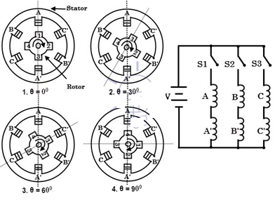
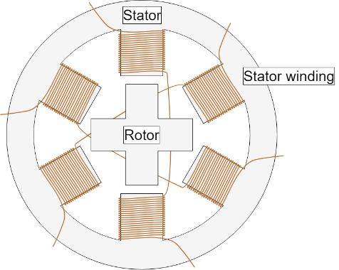
Consider the schematic diagram of a 3-phase, 6 stator poles and 4 rotor teeth is shown in figure below.
When the phase A-A’ is supplied with a DC supply by closing the switch -1, the winding become a magnet which results one tooth become North and other South. So, the stator magnetic axis lies along these poles.
Due to the force of attraction, stator coil North Pole attracts nearest rotor tooth of opposite polarity, i.e., South and South Pole attract nearest rotor tooth of opposite polarity, i.e., North. The rotor then adjusts to its minimum reluctance position where the rotor magnetic axis exactly matches with stator magnetic axis.
Working of Variable Reluctance Stepper Motor
When the phase B-B’ is energized by closing switch -2 keeping phase A-A’ remain de-energized by opening switch-1, winding B-B’ will produce the magnetic flux and hence the stator magnetic axis shifts along the poles thus formed by it. Hence the rotor shifts to the least reluctance with magnetized stator teeth and rotates through an angle of 30 degrees in the clockwise direction.
When the switch-3 is energized after opening switch-2, the phase C-C’ is energized, the rotor teeth align with new position by moving through an additional angle of 30 degrees. By this way, the rotor moves clockwise or counterclockwise direction by successively exciting stator windings in a particular sequence.
The step angle of this 3-phase 4-pole rotor teeth stepper motor is expressed as, 360/ (4 × 3) = 30 degrees (as step angle = 360 / Nr × q).
The step angle can be further reduced by increasing the number of poles on the stator and rotor, in such case motors are often wound with additional phase windings.
Permanent Magnet Stepper Motor
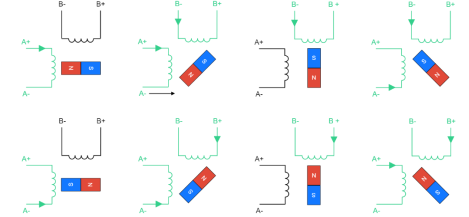
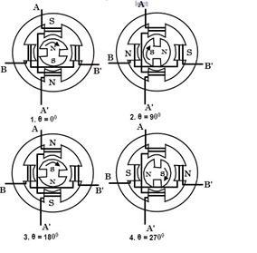
The operation of this motor works on the principle that unlike poles attract each other and like poles repel each other. When the stator windings are excited with a DC supply, it produces magnetic flux and establishes the North and South poles.
Due to the force of attraction and repulsion between permanent magnet rotor poles and stator poles, the rotor starts moving up to the position for which pulses are given to the stator.
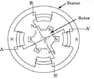
Consider a 2-phase stepper motor with two permanent magnetic rotor poles as shown in the figure below.
Working of Permanent Magnet Stepper Motor
Working of Hybrid Stepper Motor
Working of Hybrid Stepper Motor
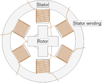
Stepper motors have a stationary part (the stator) and a moving part (the rotor). On the stator, there are teeth on which coils are wired, while the rotor is either a permanent or a variable reluctance iron core.
Figure 1 shows a drawing representing the section of the motor is shown, where the rotor is a variable-reluctance iron core.
Cross-Section of a Stepper Motor
The basic working principle of the stepper motor is the following:

Stepper Motor Steps
There are four different driving techniques for a stepper motor:

Wave Mode Steps

Full-Step Mode Steps
Half-Step Mode Steps

Microstepping
The circuit diagram of a simple stepper motor controller using only elementary parts. The driver circuit uses, four transistor (SL100) to drive the motor windings, two NOT gates and one XOR gate to decode the two- bit control logic to drive the four windings of the motor.
The diodes D1 to D4 protects the corresponding transistors from transients generated during the switching of motor windings. d0 and d1 are the control logics which determines the direction of rotation as well as speed.
An Electric Car is an automobile by itself and consists of many components and a large cluster of wires connecting them all. But there are few basic bare minimum materials for an Electric Car which is shown in the block diagram below.
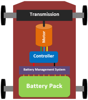
Vital Parts of an Electric Car
The Battery Pack is the fuel source of the car, since there are hundreds of cells arranged to form a battery pack a special circuit is required to monitor these cells, this circuit is called as the Battery Monitoring circuit.
The DC voltage from battery cannot be used to drive a motor so we need the controller which drives the motor, and the Transmission system transfers the rotational energy from motor on to the wheels through some gear arrangements.
EV Batteries
Batteries are the fuel source for Electric Cars, but it is also important to know that batteries are not the only source of fuels. There are other alternatives to power an EV like a Fuel cell or super capacitors but both of them are still in development stage and no commercial cars on the road use them.
The first think you should know about batteries in EV is that, unlike your mobile phone which has only one battery EV’s are powered by hundreds if not thousands of batteries joined together as a pack.
Cell
The cell refers to a single battery. There many different sizes and shapes for a cell based on the chemistry. Most commonly used chemistry is the Lead-Acid Batteries and Lithium Batteries. These batteries are available in many different shapes like cylindrical, Coin, Prismatic and Flat type few of which are shown below.
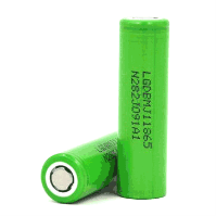 -Lithium
 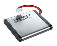 Pouch cells (Prismatic) - Lithium
The voltage rating of the cells (per cell) will be anywhere from 3.7V for a lithium batteries and a maximum of 12V for Lead-Acid batteries.
Battery Module
To get the higher voltage from 3.7v lithium cells, battery packs are used which are formed by combining more than one battery together. When two batteries are connected in series their voltage ratings is added and when two batteries are connected in parallel their Ah rating is added.
For example, assume we have 3.7V 2000mAh Lithium batteries. If you connect two of these in series the resulting system is called a module and this module will have 7.4V 2000mAh.
Likewise, if we connect two of these in parallel the resulting module will be 3.7V 4000mAh.
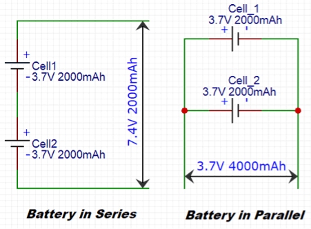
A single lithium cell voltage and Ah rating is not enough to drive an EV, so these cells are connected in series and parallel configuration to increase the resulting system voltage. This pack is called as a module.
Battery Pack
Once the system Voltage and Ah rating is obtained by combining various modules in series and parallel configuration this set-up should be placed inside the EV. Lithium cells are unstable in nature any mishap like short circuit or excess charging or discharging can make there batteries get very hot leading to fire or explosion. So, the voltage current and temperature of each cell should be monitored for a safe operation. The duty of monitoring the cells during the charging and discharging procedure is given to the circuit called Battery Management system or BMS for short.
So, once the battery modulus is ready it should be connected to the BMS and a cooling system for safe operation of battery. The complete set-up is kept in a steel casing to prevent mechanical damage.
This complete arrangement along with the BMS, cooling system casing and the battery modules all together is called as a Battery Pack of a car.
In BLDC Hub type motor, the rotor of the magnet is the wheel itself, meaning there is no need of coupling arrangement since the rim of the wheel forms the motor. These motors are also called as the BLDC out runner motor. Advantage of this type of motor is that there is less mechanical loss and since there is no transmission unit cost and weight is reduced.
BLDC In-runner Motors: Another type of BLDC motor are the In-runner types. They are used in applications where a transmission unit is required. They are normally coupled along with a differential for 3-wheeled or 4-wheeled EVs.
These motors look like normal motors with a shaft and the shaft rotates when the motor is powered.
Brushed DC motors: The Brushed DC motor also known as DC series motor was the preferable choice for all old Electric cars. These motors provide a lot of torque which could easily give a sporty feel to the EV.
The pull/pick-up of the EV would be almost at par with an average conventional car that these motors were used by drag racers during then.
AC Induction Motors: Most Modern day Electric cars like the Tesla uses an AC Induction motor. The Tesla model S for instance uses a 3-phase AC Induction Motor. The reason why these motors are selected is that they do not have permanent magnets within them and thus low cost.
It also has good life since there are no magnets, magnets would lose their tendency in day course.
The downside of the motor would be that it is hard to control the speed and torque of the motor and advanced circuitries are required.
Controller
The controller gets all the inputs form the user like the amount of throttle (acceleration), breaks pressure, driving mode etc and controls the speed of the motor accordingly.
If motors are considered to the muscle of a car, controller is its brain. A controller is often a generic term and it might include other circuits like a DC-DC converter, Speed controller, Inverter etc.
The DC-DC converter is used to power all the peripherals of the car like the infotainment system, Headlights and other low- level electronic devices.
Apart from this the controller also takes care of regenerative braking. It is the process of converting kinetic energy into electric energy.
That is when the EV runs down a slope the motor are rotating freely due to the kinetic energy, at this situation the motors can be made to act as a generator so that the power thus obtained can be used to charge the batteries.
EV Chargers
Another important component in an EV which requires advancement is the Chargers. An average E-Car takes a minimum of 5 hours to get charge that combined with its very low mileage becomes a disaster.
It gets plugged into the AC mains and converts the AC to DC to charge the batteries. But there are more to add to it. Charging is a process in which the batteries and charger should coexist you cannot push current inside a battery if the battery is not ready to accept it. There are many types of chargers; the most common types are discussed below.
Level 1 Charger: These are the most basic chargers and it is probably the one that you get along with your car. They take a long time to charge the batteries since they operate in 120V AC.
They convert this 120V AC to DC and use it to charge the batteries. The current rating of the charger will also be low somewhere near 8-10 A, this means you will be sending less current and thus taking a long time to charge your batteries overnight. On the positive side, this method improves the life cycle of the battery since our charging current is less.
Level 2 Charger: These are a bit faster that Level 1 charger, it depends on the manufacturer to provide you with Level 1 or Level 2 charger. Level 2 chargers operate on higher voltages like 240V or above and also have high current rating near 40A to 50A. This makes the car to get charged faster.
Level 3 chargers: Level 3 chargers are the game changers, this are also called as the super chargers or fast chargers. They can charge your car to 60% of its total capacity within 30 minutes.
Many governments see a greater use of battery electric vehicles (EVs) as an important way to fulfil their environmental goals. The absence of local exhaust emissions can contribute to less local air pollution, and with a higher share of renewable energy sources in the electricity production, EVs can also contribute to reducing global emissions from transport. However, the environmental impact of large-scale EV adoption is not obvious as it cannot be assumed that conventional vehicles (CVs) currently on the road are simply replaced by EVs and that individual behaviour otherwise stays the same. Potential EV users benefit from an increasing availability of EV models with greater comfort and better driving performance. Furthermore, EVs have the potential to be cheaper to run and maintain than comparable CVs. To obtain these benefits, however, the consumer must presently accept a limited driving distance between charges and that charging time, depending on the available facilities where the car is parked, takes minimum 20 minutes for recharging up to 80% battery capacity and usually several hours to reach full capacity. As a result, there are limits to the travel that can be performed with an EV, and for many car users it would not be possible to exchange their current CV with an EV without some level of adaption in their daily way of travel. For example, commuters with more than 75 km distance to work (15% of commuting trips (TU 2015)) would have uncertainty about getting home, e.g. in cold weather after work if they use a EV with today’s battery capacity. Therefore, they would need to either find charging possibilities during the day, which could include detours, or to use other transport alternatives. Both the benefits and limitations will most likely have an effect on the EV market and it is therefore very useful to know more about potential users’ EV travel. Recent decades have provided a number of studies regarding the use of EVs using different methodologies. Due to a lack of information about actual EV usage, many studies have instead been based on information about current usage of CVs with the assumption that car users do not change behaviour whether they use a CV or an EV. Such information has then been obtained from CV odometer readings at refuelling , from national travel surveys or from CV journeys measured with GPS These studies find that with the driving distances possible with the EVs currently available, a large share of the households would be able to maintain their current way of travel with only a minor level of adaption. These studies rely on simple assumptions about the effect of range limitations on usage that may be problematic. This is also indicated in the results of research from consumer choice studies on EV consumer acceptance, which show that the driving distance possible to cover on a fully charged battery is of great importance to the potential users The above mentioned studies on car usage base their conclusions on data from CV usage or data from hypothetical settings, which might not be representative for actual EV user behaviour. As the EV market is still quite immature in most countries, personal vehicle trials are instead often used to obtain information about EV usage, including daily distances, location, charging activity and driving behaviour. Data is then collected by monitoring households driving an EV in their usual routines over an extended period of time. Golob & Gould (1998) use such a trial to assess the changes in daily vehicle usage if households were using an EV instead of a CV. They conclude that for everyday trips, excluding infrequent long trips, a two passenger EV with a 100 mile driving range requiring overnight recharging at home would be used 88% as much as the CV it would replace in terms of daily distances.
In a three month field study in Germany, Franke & Krems (2013) found that the daily distance driven in the EVs was similar to German CV users. In another 3-month field study, Jensen et al. (2014) interviewed household members before and after a three month trial with EVs and found that even though the participants with EV experience had a more positive view on the EVs driving characteristics (such as comfort and acceleration) and found charging less problematic, they 4 expressed a higher concern with being able to maintain their current mobility need if they had to fulfil them with an EV. The only country in the world where the EV market is mature enough to base EV studies on revealed data from EV owning households is probably Norway. Klöckner et al. (2013) base their study on revealed data from the Norwegian Public Roads Administration (Statens Vegvesen) database and self-reported car use from private households who purchased either a CV or an EV. They show that an EV is generally used in multi-car households (In less than 10% of the EV households, this is their only car) and that the EV is used for the major share of the total amount of trips in the household, except when the purpose is holiday.
Furthermore, a lower level of car use is only found for single car EV households compared to single car CV households. In this study, we seek to answer how the current technological differences might affect households’ daily vehicle use. More specifically, we analyse the factors that affect EV use in a different way than CV use and quantify how these factors affect the daily distances driven in a household where both an EV and a CV are available. EVs have some obvious limitations compared to CVs, which we hypothesise will affect several aspects of transport behaviour. Finally, as EVs are an emerging technology, and most of the households in the trial would therefore most probably not have tried an EV before, we investigate how experience with the EV affects daily use. However, in the stated choice experiment in Jensen et al. (2013), experienced users were seen to value driving range higher than inexperienced users. The simplest indicator of car usage is the distance travelled in the household. Greene (1985) and Lin et al. (2012) specifically investigate the distributions of daily vehicle usage for CVs in order to study the implications for EV and hybrid electric vehicle use, respectively. They suggest the gamma distribution to be best at representing vehicle use in households, but to our knowledge, similar analyses have not been conducted on actual EV data to investigate whether the daily vehicle usage is different when using an EV compared to a CV. Another indicator of usage would be to look at individuals’ decision to travel by a certain mode instead of other modes. The literature contains many mode choice studies but we are not aware of such studies particularly looking at which factors would affect the choice of EV for a trip or a journey.
Operation
Battery Backup for USV Operation
The TSP-BCMU360 module extends any 24VDC or 48VDC power supply to a DC-USV (uninterruptable DC Power supply), this is achieved by the connecting a 12V lead-acid battery to the BATT_IN connector of the unit.
During normal operation, the connected power supply provides energy to load with a voltage level of Vin –0.5V as well as charging the connected battery.
If the connected supply fails, the battery is then connected to the load (buffer mode), a step- up converter is used to maintain the selected output voltage level, Vnom - 6% (typical).
Dual Inputs for Redundancy
The module provides two inputs to connect two power supplies to facilitate a redundant system. If one of the two connected sources fails then the second supply will provide energy to load maintaining the desired operation of the unit.
The unit is designed to function with the TRACO POWER TSP series, but due to its standalone nature it can be used with any type of fully stabilized 24V or 48V power supply.
Output Voltage Level and Efficiency
The TSP-BCMU360 module functions with both 24VDC (15A) and 48VDC (7.5A) supplies. The desired voltage is selectable by means of a jumper located on the side of the unit. It also offers very high efficiencies with up to 96% and 98% efficiency in normal mode for 24V and 48V modes respectively. In the buffer mode efficiencies are as high as 92% and 89% for 24V and 48V modes respectively.
Battery
When the input DC voltage is present, the TSP-BCMU360 unit will automatically charge the connected battery to a set end of battery charge voltage level, factory set for 25ºC for lead-acid batteries, using a constant current charging method of 1A (typical).
As the battery voltage approaches the end of battery charge voltage level, the current will decrease proportionality; this characteristic is shown in Figure . The user can adjust the set end of battery charge voltage level by means of the “Battery Voltage Adjust” potentiometer.
The module also provides an input connector for a temperature compensation probe. If this probe is connected, the unit will automatically compensate the end of battery charge voltage level depending on the measured temperature.
The connection of the temperature probe also negates the need to change the potentiometer to compensate for a new temperature.
The battery end voltage compensation curve is shown in Figure.

References:
o Principles of Electric Machines and Power Electronics Book by P. C Sen
o Principle Of Electrical Machines Book by Rohit Mehta and V.K. Mehta
o Theory & Performance Of Electrical Machines Book by J. B. Gupta
o Electrical Machines Book by S. K. Bhattacharya