Unit 1
Introduction to Control Systems & its modelling
A control system is a set of mechanical or electronic devices which control the other devices. In control system behaviours of the system is desired by differential equations.
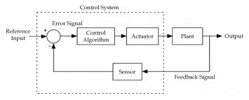
Fig 1 Control system with sensors in feedback
The above figure shows a feedback system with a control system. The components of control system are:
i) The actuator takes the signal transforms it accordingly and causes some action.
Ii) Sensors are used to measure continuous and discrete process variables.
Iii) Controllers are those elements which adjust the actuators in response to the measurement.
Key takeaway:
1) The feedback control system is having a sensor.
2) These sensors help to improve accuracy by generating error signal.
1.2.1 Open loop systems:
This is the loop of control system without any feedback. In this the control action is not dependent on the desired output.
 Fig. 2 open loop control system
Example of open Loop systems are the traffic signals, Automatic washing machine and in fields control d.c. Motor.
1.2.2 Closed loop systems:
This is a type of control system with feedback. In this type of system, the control action is dependent on the desired output.

Fig 3 Closed Loop control system
The error signal is again fed to controller to the error and get desired output.
Key takeaway:
1) The open loop systems are without feedback.
2) The closed loop systems use feedback.
Transfer function:
It is the ratio of Laplace transform of the output to Laplace transform of input with all initial conditions zero.

Fig 4 Transfer function
Poles and zero of a Transfer Function: -
The transfer function can be represented by the ratio of two polynomials
G (S) = a0sn+a1 sn-1-------+an/b0sm+b1sm-1+-----+bn
a0—an ---- constants
G(S) = K(s+z1) (s+z2) (as2+bs+c)/(S+A) (s+p2) (As2+Bs +c)
K= a0/b0 (Gain of system)
For poles –They are the values of s for which
G(S)
(S+p1) (S+p2) (A
S= p1, -p2, -B± B2-4Ac/2A
For ZEROS – They are the values of s for which
G(S)
S=-z1, -z2, -b± b2-4ac/2a
1)Location of poles and zeros in s place determines the reliability of the system
(2) There can be multiple poles and zeros
(3) The numerator of transfer function when equalized to zero gives zero of system
(4) The denominator of transfer function which equalized to zero gives poles of system.
The transfer function of a linear time invariant system is the ration of Laplace transform of the output to input.
(a) For open Loop system

Fig 5 Open Loop System
G(s) = c(s)/R(s) -------(1)
(b) For closed Loop system

Fig 6 Closed loop system
G(s) – forward amplification
H(s) _ Reverse amplification
Above system is with negative feedback.
Positive feedback is used only in oscillators and other use is not known as discussing only negative feedback.
[ R(s) – c(s) H (S)] G(s) = c(s)
R (s) G(s) = [1+G(s) H(s)] c(s)
C(s)/R(S) = G(S)/1+G(s) H(s)
S0, the transfer function of closed Loop system is
C(s)/ R(S) = G(s)/ 1+G(S) H(S) --------(2)
If numerator of above equation (2) is equalized to zero we get zeros of closed Loop Transfer function [G(S) = 0]
If dominator of equation (2) is equaled to zero we get polls of the closed loop transfer function [ 1+G(s) H(S) = 0]
1+ G(S) H(s) = 0 [ characteristic Equation]
Stability of the system is determined by the location of its poles.
The transfer function of a linear time invariant system is the ratio of Laplace Transform
Comparisons between open Loop and Closed Loop system
Open Loop System | Closed Loop system |
1.It does Not have any feedback. | 1. This system comprise of feedback |
2.As no feedback so easier to build. | 2.As it has feedback so difficult to build |
3.Theaccuracy of this system depends on the calibration of input. | 3.They are accuracy because of the feedback. |
4.Open Loop system are more stable. | 4.In closed Loop system stability depends on system components. |
5.optimization is not possible | 5. Optimization is possible |
6.These systems are not reliable. | They are more reliable |
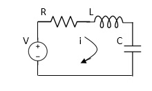
Fig 7 Electrical System
Applying Kirchoff’s voltage Law
V= Ri +Ldi/dt +1/c
V= Rdq/dt + L d2q/dt2+q/c
Now By kirchoff’s current low
I= V/R+ 1/L  + cdv/dt
But V= dø/dt
I= 1/R dø/dt + 1/L ø+cd2ø/dt2
But v= dø/dt
I= 1/R dø/dt+ 1/L. ø+c d2ø/dt2
Q.2 For the given mechanical system below draw the analogus system (force. Voltage) & find V0(s)/V1(s)
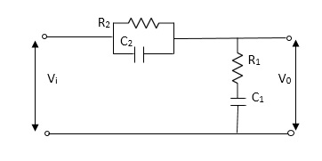
Fig 8 electrical system
Soln.
Let Z1 = R2 11 1/c2
=R2*1/c2s/R2+1/c2s
Z1= R2/1+R2c2s
Let Z2 = R1+1/c1s
Z2= 1+R1c1s/c1s
V0(s)/vi(s) = z2/z1+z2
= 1+R1c1s/c1s/R2/1+R2c2s+1+R1c1s/c1s
V0(s)/v0(s) =(c1+R1c1s) (1+R2c2s)/R2c1s+1+sR1c1s2R1R2c1c2
Armature Controlled dc motor:
In armature-controlled motors the time constant is small and hence response is last the efficiency is better than field cannot. The transfer function is calculated below.

Fig.9 Armature controlled d.c. Servomotor.
Applying kVL in armature circuit
V = Raia+ Ldia/dt +E-----(5)
Where
V= applied voltage
Ra = armature resistance
La = Armature inductance
Ia= Armature current
If= field current
E= Induced emf in armature
T= Torque developed by motor
But E= Kb w
E= kbdø/dt --------(6)
W =angular velocity
Kb= back emf
T= k ia-----(7)
The equation for torque will be
T= Jd2ø/dt2+Bdø/dt --------(8)
Taking Laplace of equation (5), (6), (7), (8)
V(S) – E(S) = I1(s) (Ra+sLa)
E(s) = kb s (s)
(s)
T(s) = k Ia (s)
T(S)= (s2J+SB)  (S)
(S)
T(S) = (SJ+B) s (S)
(S)
 (S)/v(s) k/(Ra+sla) (Js +B) s+ kkbs ------(a)
The Block diagram representation for above equation (a) is shown below.
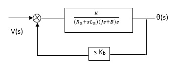
Fig. 10 Block diagram for armature-controlled d.c. Motor
Field controlled D.C. Servomotor:
For field-controlled D.C. motor the ratio L/R is large which means time controller for field circuit is large
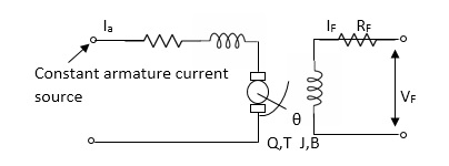
Fig.11 circuit for field-controlled D.C motor
Applying KVL in field circuit
Vf= Rf If +Lf d If/dt------(10)
T = k øIa
ø If
ø= kfIf
:. T= kkfIa If
Let k, = KIa
T= k’ Kf If --------(11)
Dynamic equation for torque is
T= Jd2 /dt2 +Bd
 /dt ------- (12)
Taking Laplace of above equations
Vf(s) = Rf If (c)+SLf If(s) [Rf+SLf]
If= Vf(S)/Rf+ SLf--------(13)
T(s) = (S) [s2J+SB] --------(14)
T(S) = kkfVf(s)/Rf+SLf------ (15)
From equation (14) and (15) we get
 (s)/ vf(s) = kkf/s (sJ+B) (Rf+sLf)
The block diagram representation of above equation (16) is shown in figure below

Fig. 12 Block diagram for field-controlled d.c. Servomotor
1.5.1 Translational mechanical system:
The motion that takes place along a straight line is called translational motion. The forces that resist motion are -
Inertia: A body with mass ‘N’ acceleration ‘a’ will produce inertia fm(t)= malt N’ acceleration ‘a’ will produce inertia
fm(t)= M a(t)
In terms of velocity
Fm(t) = M dv(t)/dt
In terms of displacement
Fm(t)= Md2/dt2µt
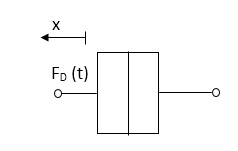 Damping force: The damping force is proportional to velocity for vis case function
F0(t) = B(t) = B dx(t) /dt
B Damping coefficient N/M sec
Fig 13 Damping force
Spring force: A spring stores potential energy. The releasing force of a string is proportional to the displacement.
 Fk(t)
Fk(t)  x(t)
x(t)
Fk(t) = k x (t)
Fk(t) = k 
K = string constant N/m.
Fig 14 Spring force
1.5.2 Rotational mechanical system:
The motion of a body about a fixed axis is called as Rotational motion. The types of torques which can resist the motion are
Inertial Torque: - The inertial torque is the product of moment of inertia I and angular acceleration.
TI(t) = J (t)
(t)
TI(t) = Jd/dt w(t)
TI(t) = Jd2ø(t)/dt2(N-m)
W (t) – Angular velocity
Ø(t) = Angular displacement
Damping Torque: - it is product of damping efficient B and angular velocity w
T0 (t) = B w(t)
T0(t) = B d/dt ø(t)
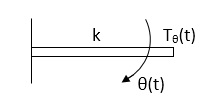 Spring Torque: - It is the product of torsional stiffness and angular displacement
Tø(t) = k ø(t)
K = N.m/rad
Fig 15 Spring Torque
D’Alembert’s Principle
For any body, the algebraic sum of externally applied forces and the forces resisting motion in any given direction is zero.
Ex.
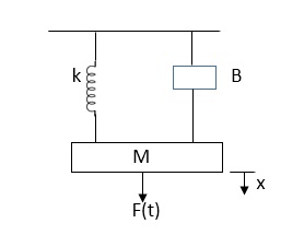
In above figure applying D’Alembert’s principle to write the equation of motion
As force f(t) acls downwards all other forces (of k,B,x)acls Opposite to it to considering f(t) as the and all other forces negative.
F(t)+fm (t) + fD(t) +fx(t) =0
f(t)- M d2x(t)/dt2+B dx(t)/dt +x(t)
Q.1 Draw the free body diagram and write the differential equation for system below.
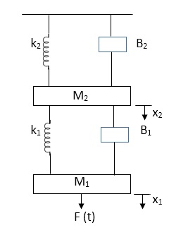
Fig 16 Mechanical system
Soln: The free body diagram for M1 will be
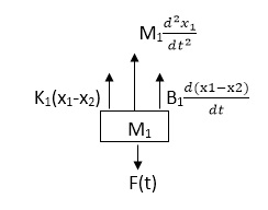
Fig 17 FBD
F(t) = M1 d2/dt2x1+ B1 d/dt (x1-x2)+ k1(x1-x2)
Similarly, for M2we have
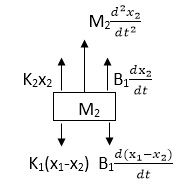
Fig 18 FBD
K1(x1-x2) + B1d/dt(x1-x2) = k2x2+M2d2/dt2+B2dx2/dt
Analogy Between Electrical and Mechanical System:
Force -voltage | Force -current | Mechanical Translatory | Mechanical Rotational |
1.Voltage (v) | Current | Force (f) | Torque (T) |
2.Charge(q) | Flux (ø) | Displacement(x) | Angular Displacement(ø) |
3.current. | Voltage | Velocity v(t) | Angular velocity(w) |
4.Inductance(l) | Capacitance(c) | Mass (m) | Moment of inertia (J) |
5. Resistance(R) | Conductance G= (1/R) | Damping coefficient (B) | Damping Coefficient (B) |
6.Reciprocal of capacitance(1/c) | Inverse of Inductance (1/L) | Stiffness (K) | Stiffness(K) |
Advantages of Block diagram reduction technique:
- Very simple to Construct the Block diagram of complicated electrical & mechanical systems.
- The function of individual element can be visualized form block diagram
- Individual as well as overall performance of the system can be studied by the if shown in Block diag.
- Overall CLTf can be easily calculated by Block diag reduction rules.
Disadvantages of Block diagram reduction technique:
It does not include any information above physical construct of system (completely mathematical approach).
a) Source of energy in generally not shown in the block diag so w.gdiff. Blockdiag can be drawn for the same function
CLTf: -ve feedback
C(s)/R(s)= G(s)/1+G(s)H(s)
CLTF: +ve feedback
C(S)/R(S) = G(S)/1-G(s)H(S)
Rules of Block diagram Algebra:
Block in cascade


Moving summing point after a block

Moving summing point ahead of block

Moving take off point after a block

Moving take off point ahead a block

Eliminating a feedback Loop

Fig 19 Block Diagram Reduction Techniques
Q. Reduce given B.D to canonical (simple form) and hence obtain the equivalent Tf = c(s)/ R(S)?


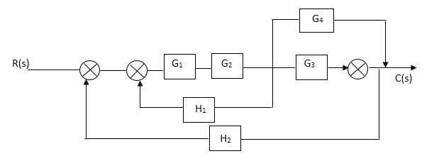


 Sol:-
Sol:- 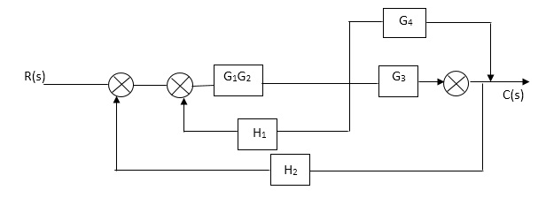


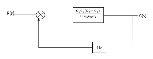
Fig 20 Final reduced block diagram
C(S)/R(S) = (G1G2) (G3+G4)/1+G1G2H1)/1-G1,G2(G3+G4) H2/1+G1G2H1
= G1G2(G3+G4)/1+G1G2H1-G1G2H2(G3+G4)
=G1G2(G3+G4)/1+(H1-H2)(G1G2) (G3+G4)
C(s)/R(S) = G1G2(G3+G4)/1+(H1-H2(G3+G4)) G1 G2
Q) Reduce the Block diagram
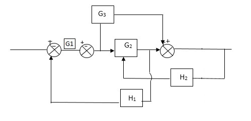
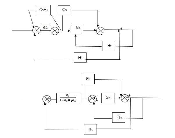
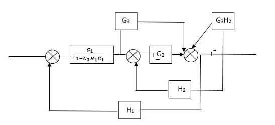
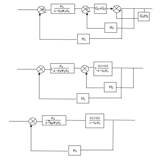
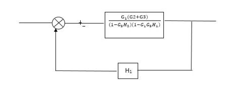
Fig 21 Final Reduced Block diagram
C(s)/R(s)= G1(G3+G2)/(1-G1G3X1) (1-G2X2) H1
= G(G3+G2)/(1-G3G1H1) (1-G2H2) + G1H1(G3+G2)
= G1(G3+G2)/1-63G1H1-G2H2+G1H1(G3+G2H1
=G1(G3+G2)/1-G3H2+G1G2H1(1+G3H2)


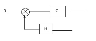
Fig 22 Block Diagram

Fig 23 SFG
Q:-
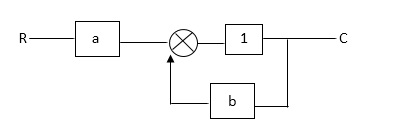
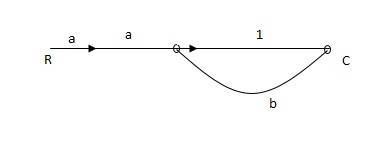
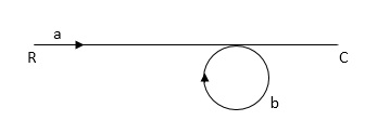
Fig 24 SFG for the block diagram
Ra+cb =c
c/R= a/1-b
Diagram:-
RULES:-
1) The signal travels along a branch in the direction of an arrow.
2) The lip signal is multiplied by the transmittance to obtain the o/p.
3) I/p signal at a node is sum of all the signals entering at that node.
4) A node transmits signal at all branches leaving that node.
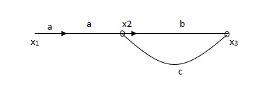
Q. The SFG shown has forward path and singles isolated loop determine overall transmittance relating X3 and X1?
Soln:-
X1- I/p node
X2-Intenmediale node
X3- o/p node
Ab- forward path (p)
Bc- 1 loop (L)
At node XQ:
X2 = x1a + x3c [Add i/p signals at node]
At node x3:
x2b =x3
(x1a+x3c) b = x3
X1ab = x3 (1-bc)
X1 = x3 (1-bc)/ab
Ab/(1-bc) = x3/x1
T= p/1-L

Fig 25 SFG
X1:- I/p node x2, x3,x4,x5,Qnlexmedili node
X0:- o/p node abdeg:- forward path
Bc, ef :- Loop [isolated]
x2 = ax1+c x3
x3= bx2
x4 = d x3+f x5
x5 = e x4
x6= g x5
x6 = g(e x4) = ge [dx3+ e f x5]
xb = ge [d (bx2) + f (e x4)]
xb = ge [ db (ax1+cx3) + fe (dx3+ fx5)]
xb = ge [db (ax1+cb (ax1+x3) +fe[cdbx2]+
f( e [db (ax1+ cx3)
x2 = ax1 + cb (x2) x4 = d bx2 + f exq
x2 = ax1 + cbx2 = db (d4) + fe/1-cb
x2 = ax1/(1-cb) xy = db x2 + f x6/g
xy = db [ax1]/1-cb + f xb/g
x5 = c db (ax1)/1-cb + efxb/g
xb = gx5
= gedb (ax1)/1-cb + g efxb/g
Xb = gx5
Gedb (ax1)/1-cb + g efxb/g
(1- gef/g) xb = gedb ax1/1-ab
Xb/x1 = gedb a/ (1- ef – bc + beef
Xb/x1 = p/ 1- (L1+L2) + L1 L2 for isolated loops
References:
1. Benjamin C. Kuo, “Automatic control systems”, Prentice Hall of India, 7th Edition.
2. M. Gopal, “Control System – Principles and Design”, Tata McGraw Hill, 4th Edition.
3. N. J. Nagrath and M. Gopal, “Control System Engineering”, New Age International Publishers, 5th Edition.
4. K. Ogata, “Modern Control Engineering”, Prentice Hall India Learning Private Limited; 5th Edition.