Unit 6
Controllers and Digital Control Systems
The controller is required when the system is unstable and the compensation will stabilize the system to improve its performance. There is one more situation when we require compensation that is when system is stable but not giving the proper performance. The type-2 or higher systems are mostly unstable and require lead compensator so that the stability of such systems can be increased. The techniques are discussed in detail below.
The elements which are used to control only two positions either ON or OFF are called as ON-OFF controllers. They do not operate for any other value. In this kind of system, the output will change in process variable. As the output is affected the process variable again changes in reverse direction and at this stage when the process variable exceeds certain limits the output is closed. As the output is closed the process variable will again change in its normal direction and when the pre-set level is crossed the output is open. This process continues making the valve ON-OFF. These are mainly used in electrical power transformer for cooling purpose.
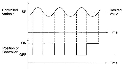
Fig 1 ON-OFF controller
The fan used for cooling the transformer uses these controllers. When the temperature (process variable) is more than the preset value the fan is turned ON and when temperature comes below the preset value the fan is turned OFF. In practical application there is a time lag in the switching of the circuit from ON to OFF and this is defined as dead time. This dead time or delay changes the actual curve of the system.
Key takeaway
The ON-OFF controller never works on any intermediate stage it will be either on or completely off.
Dead Zone: In this the system will not respond to the given input until the input reaches a particular level.
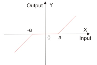
Fig 2 Dead Zone
This error reduces accuracy of system and degrades its performance. This nonlinearity can be seen in diodes, actuators.
Effects of controller are viewed on time response and stability.
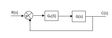
Fig 3 Controller with unity feedback system
Gc(S) = TF of the controller
G(S) = OLTF without controller
G’(S) = Gc(S).G(S)
= OLTF with controller
1. Proportional (P) Controller –
Proportional means scalar Multiplier.
Gc(S) = Kp Stability can be controlled
Q. G(S) = 1/S(S + 8)
CLTF = 1/S2 + 8S + 1
w2n = 1
wn = 1
2ξWn = 8
ξ = 4
ξ>/1 so, overdamped.
Now introducing Gc(S) = K
G’(S) = Kp/S(S + 8)
CLTF = Kp/S2 + 8S + Kp
wn = √Kp
2 ξwn = 8
ξ = 4/√Kp
If,
Kp = 16; ξ = 1; critically damped
Kp> 16; ξ< 1; undamped
Kp< 16; ξ> 1; overdamped
2. Integral (I) controller –
The transfer function of this controller is
Gc(S) = Ki/S
Integral controller is used to improve the steady state response or reduce the steady state error.
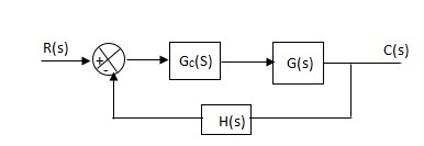
Fig 4 Integral Controller
G’(S) = Gc(S).G(S)
G(S) = 1/S + 5, Gc(S) = Ki/S
G’(S) = Ki/S(S + 5). After applying the Gc(S) the type of system is increasing and hence, the steady state error is decreasing (Refer Time Response).
Disadvantage -
By using integral controller, the stability of closed loop system decreases.
G(S) = 1/S + 5
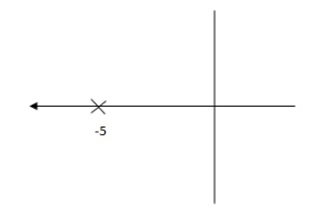
Fig 4 Pole Locations For given system
G’(S) = Ki/S(S + 5)
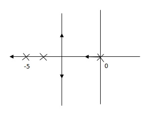
Fig 5 Pole Location after Integral controller
Fig(4), is more stable than (5) as more the away the pole from origin (imaginary axis) more is the stability.
Q. G(S) = 1/(S + 5)(S + 10)
G’(S) = Kp/S(S + 5)(S + 10)
G(S) = 1/(S + 5)(S + 10)
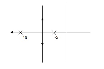
Fig 6 Root Locus Without controller
G’(S) = Ki/S(S + 5)(S + 10)
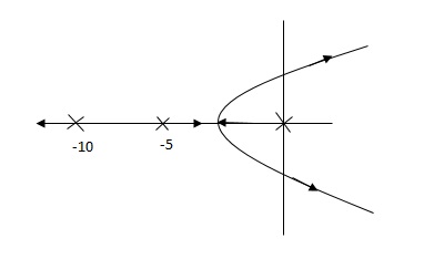
Fig 7 Root Locus Without controller
So, Fig 7 is less stable at root locus lies on the R.H.S,
3. Derivative (D) Controller -
Gc(S) = Kd(S)
They are used to improve the stability.
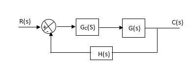
Fig 8 Derivative controller system
G’(S) = KdS/S2(S + 10)
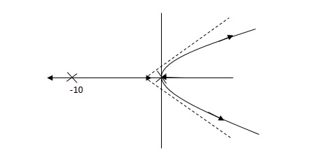
Fig 9 Root Locus for system without controller
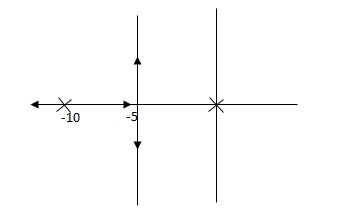
Fig 10 Root locus with controller
Fig 10 is stable i.e. more stable than the Fig 9.
Disadvantage –
It increases the steady state i.e. o/p will not track the input at steady state.
4. Proportional Plus Integral [PI] controller -
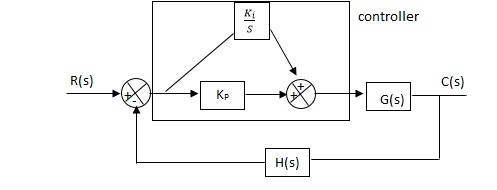
Fig 11 PI controller
Gc(S) = KpS + Ki/S
The steady state error will decrease and the stability will depend on Kp i.e. if Kp is increased/decreased than according to it stability will change (Kpα stability).
Used to reduce ess without much affecting the stability.
5. Proportional Plus Derivative (PD) Controller -
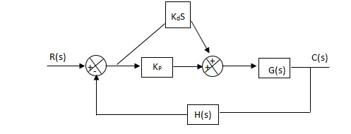
Fig 12 PD controller
Used to improve the stability without affecting much the steady state error.
6. PID controller -
Gc(S) = Kp + Ki/S + KdS
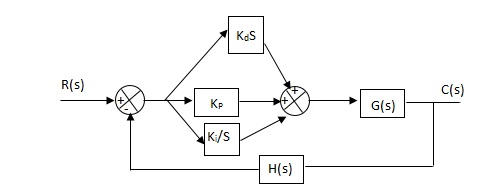
Fig 13 PID Controller
It improves the stability. It decreases the steady state error and both are proportional to Kp.
Key takeaway
Que) The block diagram of a system using PI controllers is shown in the figure 14 Calculate:
(a). The steady state without and with controller for unit step input?
(b). Determine TF of newly constructed sys. With controller so, that a CL Poles is located at -5?

Fig 14 Block diagram with PI controller
(a). Without:
C(S)/R(S) = 0.2/(S + 1)
C(S) = R(S) 0.2/(S + 1) + 0.2
For unit step
Ess = 1/1 + Kp
Kp = lt G(S)
S 0
= lt 0.2/(S + 1)
S 0
Kp = 0.2
Ess = 1/1.2 = 5/6 = 0.8
(b). With controller:
Gc(S) = Kp + Ki/S
G’(S) = Gc(S).G(S)
= ( Kp + Ki/S )0.2/(S + 1)
= (KpS + Ki)0.2/S(S + 1)
Ess = 1/1 + Kp = 0
So, the value of ess is decreased.
(b). Given
Kpi/Kp = 0.1
G’(S) = (Kp + Ki/S)(0.2/S + 1)
= (KpS + Ki)0.2/S(S + 1)
As a pole is to be added so, we have to examine the CE,
1 + G’(S) = 0
1 + (Kp + Ki)0.2/S(S + 1) = 0
S2 + S + 0.2KpS + 0.2Ki = 0
S2 + (0.2Kp + 1)S + 0.2Ki = 0
Given,
Kpi = 0.1Ki
Kp = 10Ki
S2 + (2Ki + 1)S + 0.2Ki = 0
Pole at S = -5
25 + (2Ki + 1)(-5) + 0.2Ki = 0
-10Ki – 5 + 25 + 0.2Ki = 0
-9.8Ki = -20
Ki = 2.05
Kp = 10Ki
= 20.5
Now,
G’(S) = (KpS + Ki)(0.2)/S(S + 1)
= (20.5S + 2.05)(0.2)/S(S + 1)
G’(S) = 4.1S + 0.41/S(S + 1)
Q. The block diagram of a system using Pd controller is shown, the PD is used to increase ξ to 0.8. Determine the T.F of controller?

Fig 15 Block diagram with PD controller
(1). Kp = 1
Without controller:
C(S)/R(S) = 16/S2 + 1.6S + 16
wn = 4
2 ξwn = 16
ξ = 1.6/2 x 4 = 0.2
(b). With derivative:
ξS = 0.2 to 0.8
Undamped to critically damped,
G’(S) = (1 + KdS)(16)/(S2 + 1.6S)
CE:
S2 + 1.6S + 16(1 + KdS) = 0
S2 + (1.6 + Kd)S + 16 = 0
2 ξwn = 1.6 + Kd1.6
wn = 4
ξS = 0.8
2 x 4 x 0.8 = 1.6 + Kd1.6
6. 4 – 1.6 = Kd1.6
4.8/16 = Kd
Kd = 0.3
TF = (1 + 0.3S)16/S(S + 16)
The error which is the difference between the actual value and the desired value is called ass off set error and the proportional controller is not able to control that error. When a disturbance occurs in the process value being controlled, any corrective control action, based purely on proportional control, will always leave out the error between the next steady state and the desired Value, and result in a residual error called the offset error. This error will increase as greater process demand is put on the system, or by increasing the set point.
It is the controller where the change in the rate of output is dependent on the magnitude of the input. The small value of input will cause small change in the output. The controller approximates the mathematical function of integration and hence called as integral controller.
The manual method for obtaining the characteristics is to set Ki and Kd to zero.
Keeping the values zero we set Kp such that there are oscillations at output. The below figure shows that when Kp is reduced to half the value at which it gave oscillations the output decays.
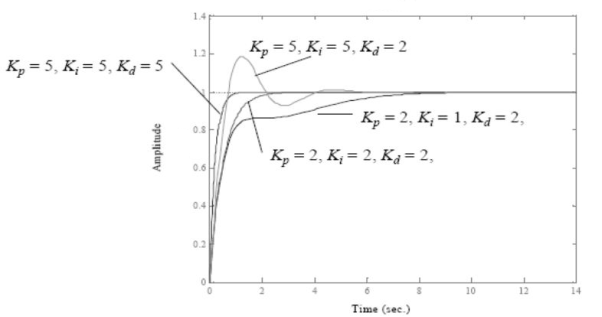
Fig 16 PID Characteristics
If Ki is increased the system becomes unstable. So, Ki can be increased to an extent. The value of Kd can be increased so that the output reaches its reference values. If Kd is increased more than it causes overshoot. The system which are overdamped require Kp to be half the value which was making oscillations at output.
Key takeaway
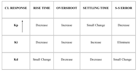
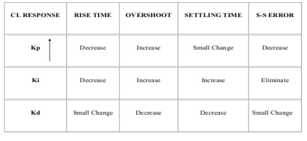
The below table shows the effect of parameter
They proposed the rules for determining values of proportional gain kp, derivative time Td and integral time Ti. They have proposed from (1) methods.
1) First Method: The basic PID controller is shown in figure below. In this method a unit step response of a plant. Is obtained if the plant has neither integrator non dominant complex conjugal poles, then the output step curve is of shape s. As shown below. These curves are generated experimentally.
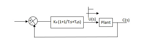
Fig 17 PID CONTROLLER
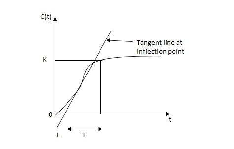
FIG 18 S-SHAPED RESPONSE CURVE

The values of KP, Ti and td should be set according to the table suggested by Ziegler Nichols tuning rules shown below.
Type of controller
Types of controller | Kp | Ti | Td |
|
P | T/L | 00 | 0 |
|
PI | 0.9T/L | L/0.3 | 0 |
|
PID | 1.2T/L | 2L | 0.5L |
|
Controller gain Gc(s)= kp(1+1/Tis+Tds)
= 1.2T / L(1+1 / 2LS+0.5 LS)
= 1.2t/l+0.6t / L2S+0.6TS
= 0.6T(2/L+1/L2S+S)
Gc(s) = 0.6 T(S+1/L)2/S
Thus , the PID controller has a pole at the origin and double zeros at S=-1/ L
Second Method -
1) Firstly, set Ti= and Td=0
2) use proportional control action only, increase kp from 0 to Kcr (Critical value).
3)then Kcr and pcr (period) are determined experimentally.

Fig 19 closed loop with proportional controller
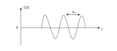
Fig 20 sustained oscillation with period pcr.
4)For this method Ziegler Nichols suggested new set of values for kp ,ti and td shown in table below.
Types of controller | KP | TI | Td |
P | 0.5Kcr |  | 0 |
PI | 0.45 KCR | 1/1.2PCR | 0 |
PID | 0.6KCR | 0.5PCR | 0.125PCR |
|
|
|
|
GC(S) = KP(1.1/Tis+Tds)
=0.6 Kcr(1+1/0.5PcrS+ 0.125 PCRS)
=0.075 KcrPcr(s+4/Pcr)2 / s
Thus, the PID controller has a pole at the origin and double zeros at s= -4/Pcr
Key takeaway
It is a PID tuning method for controlling and improving parameters like Kp, Ti and Td. They provide good regulation.
It is basically managing all the work done required with the help of machines, robots etc. This technology uses automatic control devices such as robots which do not require any human assistance. These devices have PLC, PAC etc. The advantages of industrial automation are listed below
1) They increase the production rate as the machines are capable to produce more quantity in less time.
2) As all the work done is through machines the labour requirement is reduced and hence the investment on employee is reduced. This reduces the cost of operation.
3) The quality of product becomes better as the programmed machines work and produce same and exact required products.
4) There is no need for manual assistance.
5) It is safer.
Key takeaway
- They increase the product quality and reduce work time.
- There is no need of manual assistance
IoT is Internet of Things which means the system can work on real time data. Having IoT helps to collect data and also data acquisition. This can improve the efficiency and hence the performance and accuracy. This makes system well organised and flexible. These are internet connected devices which are capable of collection real time data which helps in business and consumers also.
These devices can be used at homes like smoke detector, some smart music systems. Some which work on voice inputs like smart light bulbs. They are also used in personal physical training devices which keep a check on fitness and let the person know.
IoT Gateway devices behave as a connection bridge between IoT Sensor Network and Cloud Server. IoT Gateway devices are appearing as essential elements in bringing next-generation devices to the IoT. They assist to merge protocols for networking, helps to analyse storage and edge analytics on the data and make possible data flow safely between edge devices and the cloud.
These IoT based industrial automations are real time so accurate and precise. They can be used anywhere and any time as they are clouds. They are secure than any other systems. The improve efficiency and reduce the production cost.
They allow predictions too. As they are always collecting the real time data so they can predict if any problem is about to arise. So, that preventive measures can be thought beforehand.
Key takeaway
- They are real time data-based systems
- Highly accurate
- They can be used as smart devices
References:
1. Benjamin C. Kuo, “Automatic control systems”, Prentice Hall of India, 7th Edition.
2. M. Gopal, “Control System – Principles and Design”, Tata McGraw Hill, 4th Edition.
3. N. J. Nagrath and M. Gopal, “Control System Engineering”, New Age International Publishers, 5th Edition.
4. K. Ogata, “Modern Control Engineering”, Prentice Hall India Learning Private Limited; 5th Edition.