Unit 2
AM transmission and receiption for signal tone
The process of transferring a signal form one part of the frequency axis to the other is called Frequency translation. It occurs frequently in a Wireless communication system, that is, Frequency translation is used to transfer the pass band signal to base band signal. The Decimation is the most efficient method for the frequency translation.
For Example, consider a modulated signal S1(t) with a centered spectrum of frequency f1 and a factor of cos2π(f2–f1)t. Where, f2 is the centered spectrum of frequency of band pass filter. Figure depicts the process of obtaining upward frequency translation.

Figure 1: Frequency translation
The signal x(t) in Figure, can be obtained by the multiplication of signal S1(t) with cos 2π(f2–f1)t. Then the resultant signal x(t) is passed through the Band pass filter (BPF) which is at a centered spectrum of frequency f2. The band pass filter output results as an upward frequency translated signal s2(t).
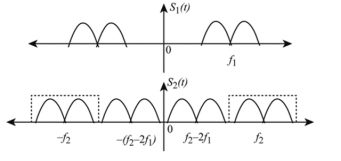
Figure 2: Frequency translated signal
The signal S1(t) represented in Figure, with a centered spectrum of frequency f1 and output of band pass filter signal results in an upward translated frequency signal s2(t).
Similarly, the downward frequency translation is estimated by multiplying the modulated signal with cos2π(f2–f1)t and then filtering out the high frequency component using the lower frequency component.
Key Takeaways:
- Frequency translation
- Need for frequency translation
A message signal 𝑥(𝑡) can be DSB modulated onto a carrier with a simple multiplication.
The modulated carrier 𝑦(𝑡) can be represented by 𝑦
y(𝑡) = 𝑥(𝑡) ∙ cos(2𝜋𝑓𝑐 𝑡) ------------------------ (1)
Where 𝑓𝑐 is the carrier frequency.
The Fourier transform 𝑌(𝑓) of the modulator output is related to the Fourier transform 𝑋(𝑓) of the message signal by
𝑌(𝑓) = 1 /2 [𝑋(𝑓 − 𝑓𝑐 ) + 𝑋(𝑓 + 𝑓𝑐 )] --------------------------- (2)
For a real 𝑥(𝑡), |𝑋(𝑓)| is symmetric about 𝑓 = 0 and |𝑋(𝑓 − 𝑓𝑐)| is symmetric about 𝑓 = 𝑓𝑐 .
The signal content that lies in the frequency domain below 𝑓𝑐 is the lower sideband. The signal content that lies in the frequency domain above 𝑓𝑐 is the upper sideband. This is the origin of the term double sideband.
If 𝑥(𝑡) is a sinusoid of frequency 𝑓𝑚, the modulated carrier can be written as
𝑦(𝑡) = cos(2𝜋𝑓𝑚𝑡) ∙ cos(2𝜋𝑓𝑐 𝑡)
= 1/ 2 cos[2𝜋(𝑓𝑐 − 𝑓𝑚)𝑡] + 1 2 cos[2𝜋(𝑓𝑐 + 𝑓𝑚)𝑡]------------------------------------- (3)
This last expression indicates that when a carrier is DSB modulated by a message sinusoid, the modulated carrier is equivalent to the sum of two sinusoids: one having the difference frequency 𝑓𝑐 − 𝑓𝑚 and the other with the sum frequency 𝑓𝑐 + 𝑓𝑚.
In the time domain, a carrier that is DSB modulated by a message sinusoid looks like this:
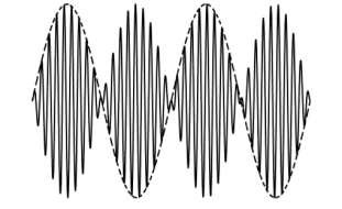
Figure 3. Amplitude Modulation – Double side band with carrier
DSB modulated carrier (solid curve) and message sinusoid (dashed curve)
A DSB modulated carrier is normally demodulated with a synchronous detector. This means that the modulated carrier is multiplied by a local oscillator and the product is then sent to a lowpass filter. With synchronous detection the frequency and phase of the local oscillator are important. Its frequency must match that of the carrier. The local oscillator phase must approximately match that of the carrier. When the modulated carrier 𝑦(𝑡) of Eq. (1) is sent to a synchronous detector, the demodulator (detector) output 𝑧(𝑡) can be written as
𝑧(𝑡) = 𝒮{𝑦(𝑡) ∙ cos(2𝜋𝑓𝑐 𝑡 + 𝜙)}
= 𝒮{𝑥(𝑡) ∙ cos(2𝜋𝑓𝑐 𝑡) ∙ cos(2𝜋𝑓𝑐 𝑡 + 𝜙)}
= 𝒮 { 1 2 𝑥(𝑡) cos(𝜙) + 1 2 𝑥(𝑡)cos(4𝜋𝑓𝑐 𝑡 + 𝜙)}
If a DC component is added to the message signal 𝑥(𝑡) before multiplication with a carrier, then the modulation scheme is known as amplitude modulation (AM). The purpose of the DC component is to permit the modulated carrier to be demodulated at the receiver by a means other than synchronous detection
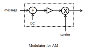
Figure 4. AM modulation
The output of the modulator can be written:
[𝑐1 + 𝑐2𝑥(𝑡)]cos(2𝜋𝑓𝑐 𝑡)
Where 𝑐1 and 𝑐2 are constants.
For AM the maximum of the absolute value of the message signal 𝑥(𝑡) is of importance; this is denoted here by 𝑝 (𝑝 ≥ 0).
𝑝 = max |𝑥(𝑡)|------------------------------------------------------------------------ (5)
It is useful to define a normalized message signal 𝑥𝑛(𝑡) as follows:
𝑥𝑛(𝑡) = 𝑥(𝑡)⁄𝑝------------------------------------------------------- (6)
The maximum of the absolute value of 𝑥𝑛(𝑡) is therefore max |𝑥𝑛(𝑡)| = 1 ---------------------------(7)
This is what is meant by normalization.
The modulator output can be rewritten as [𝑐1 + 𝑐2𝑝𝑥𝑛(𝑡)]cos(2𝜋𝑓𝑐 𝑡)
Factoring 𝑐1 out of the bracket and defining 𝜇 = 𝑐2𝑝⁄𝑐1 ------------------------(8) as the modulation index for AM, the modulator output can then be written
𝑐1 [1 + 𝜇𝑥𝑛(𝑡)]cos(2𝜋𝑓𝑐 𝑡)
The modulation index of Eq. (8) is always non-negative (that is, positive or 0) since 𝑝 is positive (by definition) and the constants 𝑐1 and 𝑐2 should always have the same sign.
The term 𝑐1cos(2𝜋𝑓𝑐 𝑡) is a residual carrier and the term 𝑐1𝜇𝑥𝑛(𝑡)cos(2𝜋𝑓𝑐 𝑡) is a DSB modulated carrier. The ratio of the peak value of the DSB term to the peak value of the residual carrier is
| 𝑐1𝜇 /𝑐1 | = μ
In the above, we recognize that 𝜇 is positive. The ratio of the peak value of the DSB term to the peak value of the residual carrier is the modulation index.
Therefore, in the analysis that appears below, we sometimes forget about 𝑐1 and use the following definition:
𝑦(𝑡) = [1 + 𝜇𝑥𝑛(𝑡)]cos(2𝜋𝑓𝑐 𝑡)-------------------------------- (10)
For AM
Consider a sinusoidal message signal. 𝑥𝑛 (𝑡) = cos(2𝜋𝑓𝑚𝑡) (11)
Three cases are of interest: 𝜇 = 1 100% modulation
𝜇 < 1 under modulation
𝜇 > 1 overmodulation
The time-domain view of the modulated carrier is shown below for these three cases.
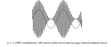
Figure 5. AM for μ=1.
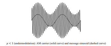
Figure 6. AM for μ<1
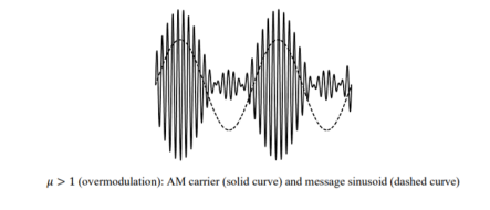
Figure 7. AM for μ >1
Key Takeaways:
- Amplitude Modulation
- Double side band AM with carrier
A general sinusoidal signal can be expressed as
f(t) = A(t) cos(t) where amplitude A and phase angle may be in general be function of time.
It is convenient to write time varying angle  (t) as , wct+ ɸ(t) therefore the sinusoidal signal may be expressed
f(t) = A (t) cos[wct + ɸ(t)]
The term A(t) is called the envelope of the signal f(t), and c is called the carrier frequency. The process of amplitude modulation consists of the amplitude of the carrier wave being varied in sympathy with a modulating signal.
A mathematical representation of an amplitude modulated signal is obtained by setting
ɸ(t)=0 in the expression for the general sinusoid
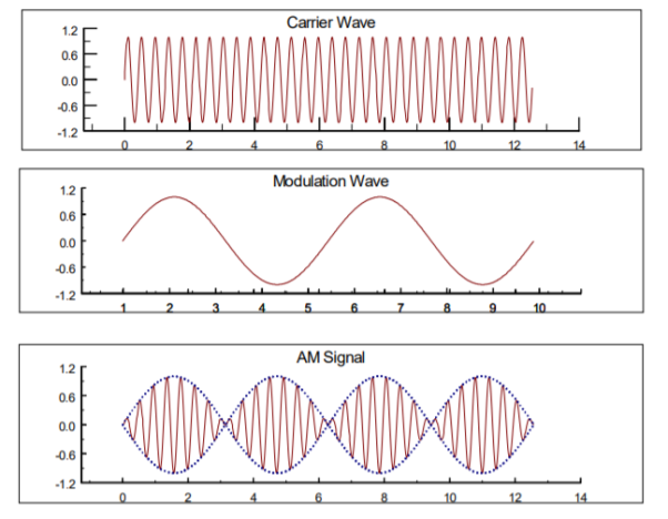
Figure 8. DSB-SC
Signal, and letting the envelope A(t) be proportional to a modulating signal f(t). The new (modulated)signal, given by
y(t) = f(t)cos wc( t) .
The spectrum of the modulated signal y(t) can be found by using the modulation property of the Fourier transform.
f(t) = ½ π  e jwt dw
F(w) =  e -jwt dt
The fourier transform of the signal f(t) e jwof is then
F{f(t) e jwot } =  e jwof e-jwot dt
=  e -j(w-wo)t dt
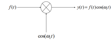
Figure 9. Modulation
Thus, the Fourier transform of f(t) may be expressed
F{f(t) e jwot} = F(w-wo)
The amplitude modulated signal y(t) may be written in terms of complex exponentials
y(t) = f(t) coswct = ½ f(t) [ e jwct + e -jwct ]
When y(t) is expressed in this form, and from the example above, it can be seen that the Fourier transform of y(t) is given by
F{f(t) cos(wct)} = ½ [ F(w +wc) + F(w-wc)]
The amplitude modulated signal y(t) in terms of complex exponentials
y(t) = f(t) cos wct = ½ f(t) [ e jwct + e -jwct]
F{f(t) cos(wct)} = ½ [ F(w+wc) + F(w-wc)]
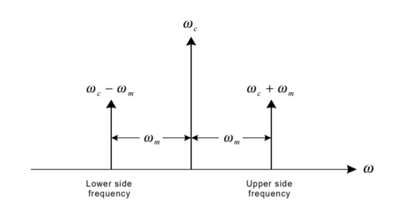
Figure 10. Fourier Spectrum
Thus, the spectrum of f (t) is translated by ± $ . It is seen that the modulation process causes the c frequencies associated with the modulating signal to disappear. Instead, a new frequency spectrum appears, consisting of two sidebands, known as the upper sideband (USB), and the lower sideband (LSB). The spectrum of the modulated signal y(t) does not contain the spectrum of the original carrier, but is still centered about the carrier frequency $. Thus, this type of modulation is c referred to as double-sideband, suppressed-carrier amplitude modulation.
If the modulating signal contains a single frequency wm, then wUSB=wc+wm, and wLSB=wc - wm .If modulating signal f(t) has a bandwidth of wbw , then F($), the spectrum of f(t), will extend from -wbw to +wbw . The upper sideband of the spectrum of the modulated signal Y(w) will extend from wc to wc+wbw . Likewise, the lower sideband will extend from wc -wbw to wc . Both the negative and positive frequency components of the modulating signal f(t) appear as positive frequencies in the spectrum of the modulated signal y(t).
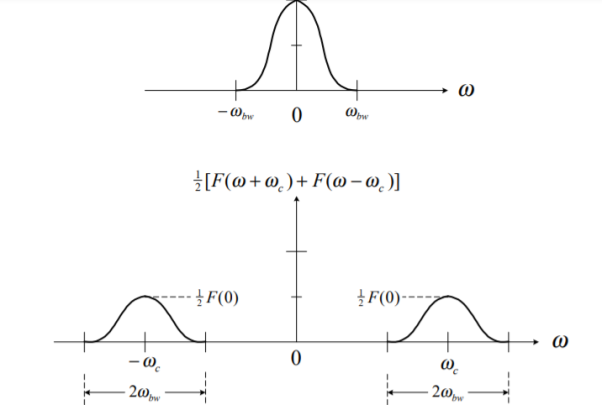
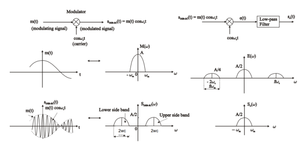
Figure 11. DSB modulation and its representation in frequency domain
Key Takeaways:
- Double side band modulation with suppressed carrier
- Its representation in frequency domain
The lower and upper sidebands are uniquely related to each other by virtue of their symmetry about carrier frequency. If an amplitude and phase spectrum of either of the sidebands is known, the other sideband can be obtained from it. This means as far as the transmission of information is concerned, only one sideband is necessary. So, bandwidth can be saved if only one of the sidebands is transmitted, and such an AM signal even without the carrier is called as Single Sideband Suppressed Carrier signal.
It takes half as much bandwidth as DSB-SC or DSB+C modulation scheme.
For the case of single-tone baseband signal, the DSB-SC signal will have two sidebands:
The lower side-band: cos(2π(fc-fm)t) = cos(2πfmt) cos(2πfct) + sin(2πfmt) sin(2πfct)
And the upper side band cos(2π(fc+fm)t) = cos(2πfmt)cos(2πfct) – sin(2πfmt) sin(2πfct)
If any one of these sidebands is transmitted, it will be a SSB-SC waveform:
s(t) SSB = cos (2πfmt) cos(2πfct)  sin(2πfmt) sin(2πfct)
Where + sign represents the lower side band and – sign upper side band. The modulating signal here is x(t) = cos(2πfmt) , so let xh(t) = sin(2πfmt) be the Hilbert transform of x(t).
The Hilbert transform is obtained by simply giving (-π/2) to a signal. So the expression for SSB-SC signal is written as
s(t) SSB = x(t) cos (2πfct)  xh(t) sin(2πfct)
Where xh(t) is the signal obtained by shifting the phase of every component present in x(t) by (-π/2).
Generation of SSB-SC signal Frequency Discrimination Method:
Frequency discrimination method:

Figure 12. SSB by Frequency discrimination method.
The filter method of SSB generation produces double sideband suppressed carrier signals (using a balanced modulator), one of which is then filtered to leave USB or LSB. It uses two filters that have different passband centre frequencies for USB and LSB respectively. The resultant SSB signal is then mixed (heterodyned) to shift its frequency higher.
Phase shift method:
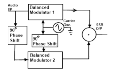
Figure 13. SSB by Phase shift method
The phase shifting method of SSB generation uses a phase shift technique that causes one of the side bands to be cancelled out. It uses two balanced modulators instead of one. The balanced modulators effectively eliminate the carrier. The carrier oscillator is applied directly to the upper balanced modulator along with the audio modulating signal. Then both the carrier and modulating signal are shifted in phase by 90o and applied to the second, lower, balanced modulator. The two balanced modulator output are then added together algebraically. The phase shifting action causes one side band to be cancelled out when the two balanced modulator outputs are combined.
Demodulation of SSB-SC Signals:
The baseband or modulating signal x(t) can be recovered from the SSB-SC signal by using synchronous detection technique. With the help of synchronous detection method, the spectrum of an SSB-SC signal centered about w= ±wc , is retranslated to the based and spectrum which is centered about w = 0. The process of synchronous detection involves multiplication of the received SSB-SC signal with a locally generated carrier.

Figure 14. Demodulation
The output of the multiplier will be
Ed(t) = s(t)ssb . Cos wct
Or ed(t) = [x(t) coswct  xh(t) sin wct] coswct
Or ed(t) = [ x(t) cos 2 wct  xh(t) sin wct coswct]
Or ed(t) = ½ x(t) + ½ [x(t) cos(2wct)]  xh(t) sin 2wct
When ed(t) is passed through low pass filter centre at  are filtered out and the output of detector is only the baseband part that is ½ x(t).
Key Takeaways:
SSB Modulation
Methods of SSB generation
Demodulation of SSB
SSB modulation is suited for transmission of voice signals due to the energy gap that exists in the frequency range from zero to few hundred hertz. But when signals like video signals which contain significant frequency components even at very low frequencies, the USB and LSB tend to meet at the carrier frequency. In such a case one of the sidebands is very difficult to be isolated with the help of practical filters. This problem is overcome by the Vestigial Sideband Modulation. In this modulation technique along with one of the sidebands, a gradual cut of the other sideband is also allowed which comes due to the use of practical filter.
BW = (fc+fv) – (fc-fm) = fm+fv
Fm-bandwidth of bandlimited message signal
Fv-> width of the vestige in frequency.
Generation:
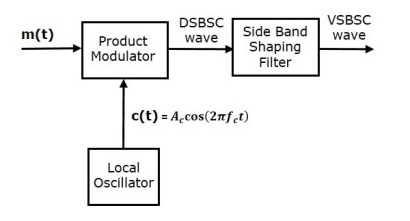
Figure 15. VSB generation
In this method, first we generate DSBSC wave with the help of the product modulator. Then, apply this DSBSC wave as an input of sideband shaping filter. This filter produces an output, which is VSBSC wave.
The modulating signal m(t) and carrier signal
Accos(2πfct) are applied as inputs to the product modulator. Hence, the product modulator produces an output, which is the product of these two inputs.
Therefore, the output of the product modulator is
p(t)=Accos(2πfct)m(t)
Apply Fourier transform on both sides
P(f)=Ac/2[M(f−fc)+M(f+fc)]
The above equation represents the equation of DSBSC frequency spectrum.
Let the transfer function of the sideband shaping filter be H(f). This filter has the input p(t) and the output is VSBSC modulated wave s(t). The Fourier transforms of p(t) and s(t) are P(f) and S(f) respectively.
Mathematically, we can write S(f)S(f) as
S(t)=P(f)H(f)
Substitute P(f) value in the above equation.
S(f)=Ac/2[M(f−fc)+M(f+fc)]H(f)
The above equation represents the equation of VSBSC frequency spectrum.
Demodulation of VSBSC
Demodulation of VSBSC wave is similar to the demodulation of SSBSC wave. Here, the same carrier signal (which is used for generating VSBSC wave) is used to detect the message signal. Hence, this process of detection is called as coherent or synchronous detection. The VSBSC demodulator is shown in the following figure.
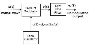
Figure 16. Demodulation of VSB-SC
In this process, the message signal can be extracted from VSBSC wave by multiplying it with a carrier, which is having the same frequency and the phase of the carrier used in VSBSC modulation.
The resulting signal is then passed through a Low Pass Filter. The output of this filter is the desired message signal.
Let the VSBSC wave be s(t) and the carrier signal is Ac cos(2πfct).
From the figure, we can write the output of the product modulator as
v(t)=Ac cos(2πfct)s(t)
Apply Fourier transform on both sides
V(f) = Ac/2 [ S(f-fc) + S(f+fc)]
S(f) = Ac/2 [M(f-fc)+M(f+fc)] H(f)
From the above equation let us find S(f-fc) and S(f+fc)
S(f-fc) = Ac2 [ M(f-fc-fc)] +M(f-fc+fc)] H(f-fc)
S(f-fc) = Ac/2[ M(f-2fc + M(f)] H(f-fc)
S(f+fc) = Ac/2 [ M(f+fc-fc) + M(f+fc+fc)] H(f+fc)
S(f+fc) = Ac/2 [ M(f+fc-fc) + M(f+fc+fc)] H(f+fc)
S(f+fc) = Ac/2[ M(f) + M(f+fc)] H(f+fc)
Substitute S(f-fc) and S(f+fc) in V(f)
V(f) = Ac/2 [ Ac/2 [ M(f-2fc) H(f-fc) + M(f+fc) H(f+fc)]
In the above equation the first term represents the scaled version of the desired message signal frequency spectrum. It can be extracted by passing the above signal through a low pass filter.
Vo(f) = Ac 2 /4 M(f) [ H(f-fc) + H(f+fc)]
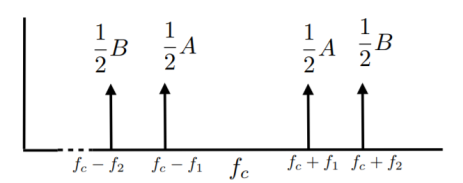
Figure 17. Spectrum of DSB signal
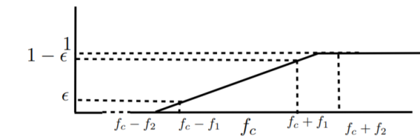
Figure 18. Frequency response of VSB filter
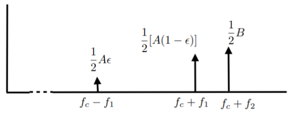
Figure 19. Output response
Key Takeaways:
- VSB
- Generation of VSB
- Output response
Spectrum of AM:
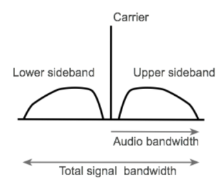
Figure 20. Spectrum of AM
It can be seen that if the top frequency that is modulated onto the carrier is 6 kHz, then the top spectra will extend to 6 kHz above and below the signal. In other words, the bandwidth occupied by the AM signal is twice the maximum frequency of the signal that is used to modulated the carrier, i.e. it is twice the bandwidth of the audio signal to be carried.
Spectrum of DSB-SC
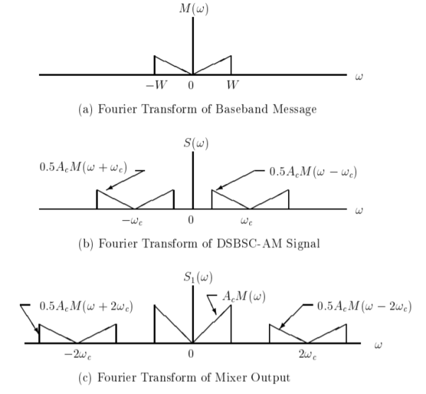
Figure 21. Spectrum of DSB-SC
When m(t) is a real signal, M(−ω) = M(ω) and S(ωc − ω) = S(ωc + ω) for 0 ≤ ω ≤ ωc
This equation shows that the component at frequency ωc + ω contains exactly the same information as the component at ωc − ω since one can be uniquely determined from the other by taking the complex conjugate.
The portion of the spectrum for |ω| > ωc is called the upper sideband and the portion for |ω| < ωc is called the lower sideband.
The fact that the modulated signal contains both portions of the spectrum explains why the term, double-sideband, is used.
Spectrum of SSB:
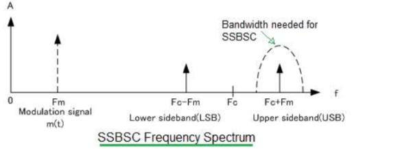
Figure 22. Spectrum of SSB
SSB-SC spectrum has only one sideband either lower or upper. There is no carrier in the transmission. It needs half of the bandwidth used for DSBSC transmission.
SSB filter is used to extract desired sideband for transmission from DSBSC signal. Half of the power is needed for transmission in SSB-SC in comparison to DSBSC.
Spectrum of VSB
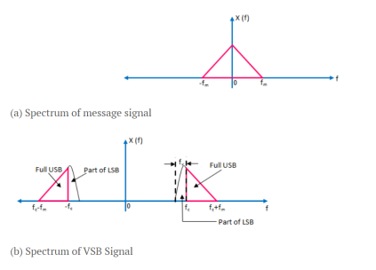
Figure 23. Spectrum of VSB
The spectrum of message signal x(t) is shown in figure. In the frequency spectrum, it is assumed that the upper sideband is transmitted as it is and the lower sideband is modified into vestigial sideband
Key Takeaways:
- Spectrum of AM
- Spectrum of DSB_SC
- Spectrum of SSB
- Spectrum of VSB
AM wave:
We know that
s(t)=Ac[1+(Am/Ac) cos(2πfmt)]cos(2πfct)]
⇒s(t)=Ac[1+μcos(2πfmt)]cos(2πfct)
Where μ is the modulation index which is equal to μ = Am/Ac
Mathematically, we can write it as
μ=Am/Ac
Hence, we can calculate the value of modulation index by using the above formula, when the amplitudes of the message and carrier signals are known.
Let Amax and Amin be the maximum and minimum amplitudes of the modulated wave.
We will get the maximum amplitude of the modulated wave, when cos(2πfmt) is 1.
Amax=Ac+Am
We will get the minimum amplitude of the modulated wave, when cos(2πfmt) is -1.
Amin=Ac−Am
Amax+Amin=Ac+Am+Ac−Am=2Ac
Ac=Amax+Amin / 2
Amax−Amin=Ac+Am−(Ac−Am)=2Am
Am/Ac = (Amax -Amin)/2/ (Amax+Amin)/2
μ=Amax-Amin/Amax+Amin
Key Takeaways:
- Modulation index
- Derivation for modulation index
Single-Sideband Suppressed Carrier
To improve power efficiency, further dropping one sideband
For monotone signal, the DSB-SC signal is
DSB−SC(t) = mAc /2 cos (ωc + ωm)t + mAc /2 cos (ωc − ωm)t
After dropping one sideband
After LPF LSB = xSSB-LSB(t) = mAc/2 cos(wc-wm) t
After HPF HSB = xSSB-USB (t) = mAc/2 cos(wc+wm)t
For a perfect modulation, the value of modulation index should be 1, which means the modulation depth should be 100%.
For instance, if this value is less than 1, i.e., the modulation index is 0.5, then the modulated output would look like the following figure. It is called as Under-modulation. Such a wave is called as an under-modulated wave.
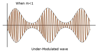
Figure 24. Under modulated wave
If the value of the modulation index is greater than 1, i.e., 1.5 or so, then the wave will be an over-modulated wave. It would look like the following figure.
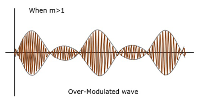
Figure 25. Over Modulated wave
As the value of modulation index increases, the carrier experiences a 180° phase reversal, which causes additional sidebands and hence, the wave gets distorted. Such overmodulated wave causes interference, which cannot be eliminated.
Key Takeaways:
- Modulation index for SSB
- Under modulated wave
- Over modulated wave
Consider the following equation of amplitude modulated wave
S(t) = Ac cos(2πfct) + Ac μ/2 cos [2π(fc+fm)t+Acμ/2 cos[2π(fc-fm)t]
The power of AM wave is equal to the sum of powers of carrier, upper sideband and lower sideband frequency components
Pt = Pc + PUSB + PLSB
We know that the standard formula for power of cos signal is
P= vrms2/ R = (vm/√2) 2/2
Where
Vrms is the rms value of cos signal.
Vm is the peak value of cos signal.
First, let us find the powers of the carrier, the upper and lower sideband one by one.
Carrier power
Pc = (Ac /√2) 2 /R = Ac2/2R
Upper sideband power
Pusb = (Acμ/2√2) 2/ R = Ac 2 μ 2 / 8R
Similarly, we will get the lower sideband power same as that of the upper side band power.
Plsb = (Acμ/2√2) 2/ R = Ac2 μ 2 / 8R
Now, let us add these three powers in order to get the power of AM wave.
Pt = Ac 2 /2R + Ac 2 μ 2 / 8R + Ac 2 μ2 /8R
Pt = (Ac 2 /2R) (1+μ 2/ 4 + μ 2 /4)
Pt = Pc(1+μ 2 /2 )
Power Efficiency:
The efficiency of modulation is given by:
Ղ= Ps /Pc + Ps = μ 2 /2 Pc / Pc + μ 2 /2 Pc = μ 2 / 2 + μ 2
Ղ= 1/1+2 = 1/3 x100 = 33%
Key Takeaways:
- Power of AM wave
- Power Efficiency
Demodulation is a key process in the reception of any amplitude modulated signals whether used for broadcast or two-way radio communication systems.
Detection is the process of detecting the intelligence out of the carrier and sidebands. If two different frequencies were passed through a mixer (non-linear device), the sum and difference components would be generated.
The carrier and sidebands of the AM signal are separated in frequency by an amount equal to the intelligence frequency. It follows that passing the AM signal through a mixer device will provide detection.
When the input to an ideal mixer is a carrier and its sidebands, the output contains the following frequencies:
The carrier frequency
Upper sideband
Lower sideband
DC component
A frequency equal to the carrier minus the lower sideband and the upper sideband minus the carrier. The detector reproduces the signal frequency by producing a distortion of a desirable kind. When the output of the detector is impressed upon a low-pass filter, the radio frequencies are suppressed and only the low-frequency intelligence signal and dc components are left.
Square-law detector:
A Square-law modulator requires nonlinear element and a low pass filter for extracting the desired message signal. Semi-conductor diodes and transistors are the most common nonlinear devices used for implementing square law modulators. The filtering requirement is usually satisfied by using a single or double tuned filter. When a nonlinear element such as a diode is suitably biased and operated in a restricted portion of its characteristic curve, that is ,the signal applied to the diode is relatively weak, we find that transfer characteristic of diode-load resistor combination can be represented closely by a square law :
V0 (t) = a1Vi (t) + a2 Vi2 (t) ……………….(i) Where a1, a2 are constants
Now, the input voltage Vi (t) is the sum of both carrier and message signals i.e., Vi (t) = Ac [1+kam (t)] cos2 fct…………….(ii)
Substitute equation (ii) in equation (i) we get V0 (t) = a1Ac [1+kam (t)] cos2 fct + 1/2 a2Ac2 [1+2 kam (t) + ka2m2 (t)] [cos4 fct]………..(iii)
Now design the low pass filter with cutoff frequency f is equal to the required message signal bandwidth. We can remove the unwanted terms by passing this output voltage V0 (t) through the low pass filter and finally we will get required message signal.
V0 (t) = Ac2 a2 m (t)
The Fourier transform of output voltage VO (t) is given by VO (f) = Ac2 a2 M (f)
Key Takeaways:
- AM Reception
- Methods of AM reception
References:
Digital Communication Systems Book by Simon S. Haykin
Principles of digital communication Textbook by Robert G. Gallager
Digital Communications Book by John G Proakis and Masoud Salehi
Digital Communications Book by Sanjay Sharma
Digital Communication Book by J.S.Chitode