Unit 3
FM transmission and reception for signal tone
But in Frequency Modulation (FM), the frequency of the carrier signal varies in accordance with the instantaneous amplitude of the modulating signal.
The amplitude and the phase of the carrier signal remains constant whereas the frequency of the carrier changes. This can be better understood by observing the following figures.
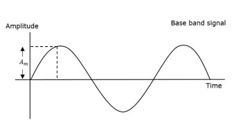
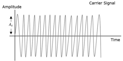
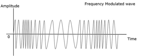
Figure 1. Frequency Modulation
The frequency of the modulated wave remains constant as the carrier wave frequency when the message signal is at zero. The frequency increases when the message signal reaches its maximum amplitude. That is, with the increase in amplitude of the modulating or message signal, the carrier frequency increases. Likewise, with the decrease in the amplitude of the modulating signal, the frequency also decreases.
Mathematical Representation
Let the carrier frequency be fc
The frequency at maximum amplitude of the message signal = fc + Δf
The frequency at minimum amplitude of the message signal = fc − Δf
The difference between FM modulated frequency and normal frequency is termed as Frequency Deviation and is denoted by Δf.
The deviation of the frequency of the carrier signal from high to low or low to high can be termed as the Carrier Swing.
Carrier Swing = 2 × frequency deviation
= 2 × Δf
Equation for FM WAVE
The equation for FM wave is −
$$s(t) = Ac cos[wct + 2πkfm(t)]
Where,
Ac = the amplitude of the carrier
wc = angular frequency of the carrier = 2πfc
m(t) = message signal
FM can be divided into Narrowband FM and Wideband FM.
Narrowband FM
The features of Narrowband FM are as follows −
- This frequency modulation has a small bandwidth.
- The modulation index is small.
- Its spectrum consists of carrier, USB, and LSB.
- This is used in mobile communications such as police wireless, ambulances, taxicabs, etc.
Wideband FM
The features of Wideband FM are as follows −
- This frequency modulation has infinite bandwidth.
- The modulation index is large, that is higher than 1.
- Its spectrum consists of a carrier and infinite number of sidebands, which are located around it.
- This is used in entertainment broadcasting applications such as FM radio, TV, etc.
Phase Modulation
In frequency modulation, the frequency of the carrier varies. But in Phase Modulation (PM), the phase of the carrier signal varies in accordance with the instantaneous amplitude of the modulating signal.
The amplitude and the frequency of the carrier signal remains constant whereas the phase of the carrier changes.
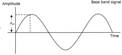
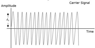
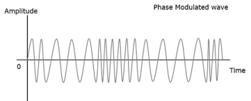
Figure 2. Phase Modulation
The phase of the modulated wave has got infinite points where the phase shift in a wave can take place. The instantaneous amplitude of the modulating signal, changes the phase of the carrier. When the amplitude is positive, the phase changes in one direction and if the amplitude is negative, the phase changes in the opposite direction.
Key Takeaways:
- Frequency modulation and its mathematical expression
- Phase modulation
The change in phase, changes the frequency of the modulated wave. The frequency of the wave also changes the phase of the wave. Though they are related, their relationship is not linear. Phase modulation is an indirect method of producing FM. The amount of frequency shift produced by a phase modulator increases with the modulating frequency. An audio equalizer is employed to compensate this.
Equation for PM Wave
The equation for PM wave is −
s(t) = Ac cos[wct + kp m(t)]
Where,
Ac = the amplitude of the carrier
wc = angular frequency of the carrier = 2πfc
m(t) = message signal
Phase modulation is used in mobile communication systems, while frequency modulation is used mainly for FM broadcasting.
Modulation index
- The amount of change in the carrier frequency produced, by the amplitude of the input modulating signal, is called frequency deviation.
- The Carrier frequency swings between fmax and fmin as the input varies in its amplitude.
- The difference between fmax and fc is known as frequency deviation.
- Fd = fmax – fc
- Similarly, the difference between fc and fmin also is known as frequency deviation. Fd = fc –fmin
- It is denoted by Δf. Therefore Δf = fmax – fc = fc – fmin
- Therefore fd = fmax – fc = fc – fmin
The modulation index of FM is defined as the ratio of the frequency deviation of the carrier to the frequency of the modulating signal
Mf = Modulation Index of FM = ∆f/fm
Key Takeaways:
- Relation between FM and PM
- Modulation index
Let the expression for carrier wave be
c(t) = Ac cos 2πfct ……………………………………(1)
And the message signal m(t) = Am cos 2πfmt ……………………..(2)
The expression for FM wave will be
SFM = Ac cos  i(t)
i(t)
SFM = Ac cos 2π [fct + Kf  dt
dt
Putting the value of m(t) in eq(2) we get
SFM(t) = Ac cos 2π [fct + Kf  dt ]
dt ]
SFM(t) = Ac cos 2π [fct + Kf  m cos 2πfmt dt]
SFM(t) = Ac cos [2πfct + 2πKf A m sin 2πfmt /2π fm t]
Cancelling 2π we get
SFM(t) = Ac cos [2πfct + Kf Am/fm sin 2πfmt]
SFM(t) = Ac cos [2πfct + ∆f/fm sin 2πfmt]
Where ∆f = Kf Am
We know that modulation index β= ∆f/fm
SFM(t) = Ac cos [2πfct + β sin 2πfmt]
Example: Consider fc=1KHz, fm =100Hz, fs =80kHz and β=5 we get
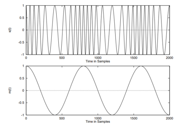
Figure 3. Spectrum of FM Single tone
A single tone FM is represented by the voltage equation:
V(t) = 12 cos[6x10 8 t + 5 sin 1250t]
Determine the following: 1. Carrier frequency 2. Modulating frequency 3. Modulation Index 4. Maximum deviation
Compare it with standard equation of single tone FM wave
SFM(t) = Ac cos [2πfct + β sin 2πfmt]
- 2πfct = 6 x 10 8 = fc = 95.5MHz
- 2πfmt = 1250 = fm = 199Hz
- β = 5
- ∆f = β fm = 5 x 199 Hz = 995Hz
A 107.6MHz carrier signal is frequency modulated by 7KHz sine wave. The resultant FM signal has frequency deviation of 50 KHz. Determine the following: 1. Carrier Swing of FM signal 2. The highest and lowest signal attained by modulating signal 3. The modulation index 𝛽
Soln:
Given ∆f = 50Khz, fm = 7Khz, fc = 107.6 Mhz
- Carrier swing = 2∆f = 2 x 50 KHz = 100 KHz
- Fmax = fc + ∆f = 107.6 + 0.05M = 107.65 MHz
- Fmin = fc - ∆f = 107.6 -0.05 = 107.55 M Hz
- Modulation index β=∆f/fm = 50K/7K = 7.14
Feature of Bessel co-efficient
Consider Eq. (1), which defines an FM signals resulting from the use of sinusoidal modulating signal. Expanding this relation, we get eq(2)
SFM(t) = Ac cos [2πfct + β sin 2πfmt]---------------------------------(1)
s(t) = Ac cos (2πfct) cos [β sin(2πfmt)] – Ac sin (2πfct) sin [β sin(2πfmt)]--------(2)
Cos [β sin(2πfmt)] 1 sin [β sin(2πfmt)]
  β sin(2πfmt)
s(t) = Ac cos (2πfct) – Ac sin (2πfct) β sin(2πfmt)]--------(2)
s(t) = Ac cos (2πfct) – β Ac sin (2πfct) sin (2πfmt) --------------------(3)
s(t) = Ac cos (2πfct) + ½ β Ac{ cos[2π(fc+fm)t] – cos[2π(fc-fm)t]} ------(4)
By using the complex representation of band pass signals
s(t) = Re[Ac exp(j2πfct+jβsin(2πfmt))]
= Re[ (t) exp(j2πfct)]
We may therefore expand  (t) in the form of complex Fourier series as follows:
 (t) =
(t) =  n exp(j2πnfmt)--------------------------------------------(5)
cn = fm  exp(-j2πnfmt)dt ------------------------------------------(6)
= fm Ac  (jβsin(2πfmt ) -j2πnfmt)] dt-----------------------------(7)
Cn = Ac/2π  [j(βsinx -nx)] dx ------------------------------------------(8)
Cn = Ac Jn(β)
Where
Jn(β) = 1/2π  sinx -nx)] dx = nth order Bessel function of first kind.
s(t) = Ac . Re[  exp [j2π(fc+nfm)t] -----------------------------------(9)
Taking the Fourier transforms of both sides of Eq(9) we get
S(f) = Ac/2  [ δ(f-fc-nfm) + δ(f+fc+nfm)]----------------------------(10)
In the figure we have plotted Bessel function Jn(β) versus the modulation index β for different positive integer values of n.
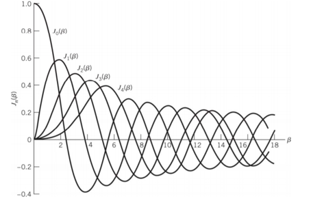
Figure 4. Bessel’s co-effecients
Key Takeaways:
- FM single tone expression
- Spectrum of single tone
- Bessel’s co-efficient
We know that
Ptotal = P carrier + P(USB1 + P USB2+ PUSB3 ………∞) + (PLSB1+PLSB2+PLSB3…………………………….∞)
Pc = Vrms 2/R = V2 / 2R = Ac 2 Jo 2 (β)/2R
Similarly, PUSB1 = Ac2 J1 2(β) /2R and PLSB1=Ac2 J-12(β)/2R
Ptotal = Ac2 Jo2 (β)/2R + (Ac2 J1 2 (β)/2R + Ac2 J3 2(β)/2R ……………… ∞) + (Ac2 J-1 2 (β)/2R+Ac2 J-2 2(β)/2R + Ac2 J-3 2(β)/2R……………………………….. -∞)
Ptotal = Ac2 /2R [-∞ +……+ J-2 2(β) +J-12(β)+Jo2(β)+J12(β)+J22β)………………∞]
Ptotal = Ac2/2R  2 (β)
2 (β)
We know that from the property of Bessel function
 n 2 (x) =1
Therefore Ptotal = Ac2/2R
Key takeaways:
- Power of FM signal and its derivation
The Bandwidth of an FM Signal The following formula, known as Carson’s rule is often used as an estimate of the FM signal bandwidth:
BT = 2(∆f + fm) Hz --------------------------------------(1)
Where ∆f is the peak frequency deviation and
Fm is the maximum baseband message frequency component.
Key Takeaways:
- Bandwidth of FM modulated signal
AM vs FM spectrum of constant bandwidth FM
Bandwidth BW = 2(D+1) W or
BW = 2(b +1)/fm
FM:
For tone modulation:
Modulation index, b = Df/fm
BW = 2(KfAm + fm)
PM:
For tone modulation:
Modulation index b=kpAm
BW = 2(kpAm+1)fm
Narrowband and Wideband FM
A narrow band FM is the FM wave with a small bandwidth.
The modulation index mf of narrow band FM is small as compared to one radian. Hence, the spectrum of narrow band FM consists of the carrier and upper sideband and a lower sideband.
For small values of mf, the values of the j coefficients are as under:
J0(mf) = 1,
J1(mf) = mf/2
Jn(mf) = 0 for n > 1
Hence, a narrow band FM wave can be expressed mathematically as under,

The (-) sign associated with the LSB represents a phase shift of 180o.
Practically, the narrow band FM systems have mf less than 1. The maximum permissible frequency deviation is restricted to about 5 kHz.
This system is used in FM mobile communications such as police wireless, ambulances, taxicabs etc.
Analysis of Narrow band FM
As we know, the expression for instantaneous frequency of FM wave is given as:
Fi = fc + Kf x(t)
Where, x(t) is the modulating signal.
The term kf x(t) represents the frequency deviation. The constant kf will control the deviation. For small values of kf, the frequency deviation is small and the spectrum of FM signal has a narrow band. Hence, it is called as the narrow band FM.
Let us consider the expression for FM wave as under:
s(t) = Ec cos[ 2πfct + 2πkf  dt]
dt]
In exponential manner we represent as
s(t) = Ec cos (t) = Ec ej
 (t)
(t)
This is written considering only real part.
Therefore s(t) = Ec ej (t) = Ec e j[cos wct +kf
  dt ]
dt ]
Let  =g(t)
=g(t)
Therefore
s(t) = Ec e j[cos wct +kf g(t) dt ]
 = Ec[1+jkf g(t)] e jwct
Also
s(t) = Rc[  ] = Ec coswct – Ec kf g(t) sin wct
This is the expression for narrow band FM.
Figure shows the generation of narrow band FM using balanced modulator.
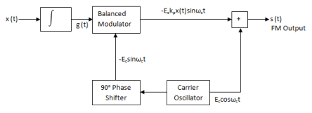
Figure 5. Generation of FM
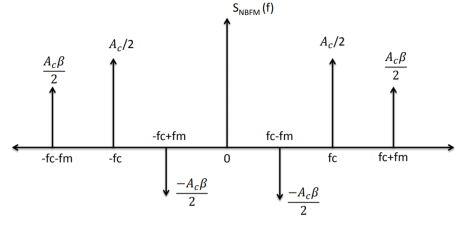
Figure 6. Spectrum of FM
Wideband FM
For large values of modulation index mf, the FM wave ideally contains the carrier and an infinite number of sidebands located symmetrically around the carrier.
Such a FM wave has infinite bandwidth and hence called as wideband FM.
The modulation index of wideband FM is higher than 1.
The maximum permissible deviation is 75 kHz and it is used in the entertainment broadcasting applications such as FM radio, TV etc.
Frequency Spectrum of a Wideband FM wave
The expression for the wideband FM is complex since it is sine of sine function.
The only way to solve this equation is by using the Bessel functions. By using the Bessel functions the equation for wideband FM wave can be expanded as follows:
EFM = s(t) = Ec{Jo(mf) sin wct +J1(mf) [sin(wc+wm)t – sin(wc-wm)t] + J2(mf)[sin(wc+2wm)t – sin(wc-2wm)t + J3(mf)[sin(wc+3wm)t-sin(wc-3wm)t+J4(mf)[sin(wc+4wm)t-sin(wc-4wm)t…………………………….(1)
Looking at equation (1), we can conclude the following points:
- The FM wave consists of carrier. The first term in equation (1) represents the carrier.
- The FM wave ideally consists of infinite number of sidebands. All the terms except the first one is sidebands.
- The amplitudes of the carrier and sidebands is dependent on the J coefficients.
- As the values of J coefficients are dependent on the modulation index mf, the modulation index determines how many sideband components have significant amplitudes as shown in fig.2 below.
- Some of the J coefficients can be negative. Therefore, there is a 180o phase shift for that particular pair of sidebands.
- The carrier component does not remain constant. As J0(mf) is varying the amplitude of the carrier will also vary. However, the amplitude of FM wave will remain constant.
- For certain values of modulation index, the carrier component will disappear completely. These values are called eigen values.
- In FM, the total transmitted power always remains constant. It is not dependent on the modulation index. The reason for this is that the amplitude of the FM signal i.e. Ec is always constant. AND the power transmitted is given by,
Pt = ( Ec/  ) 2 / R = Ec2 /2R
Where Ec = peak amplitude of FM wave
Therefore,
Pt = Ec2 /2R if R=1Ω.
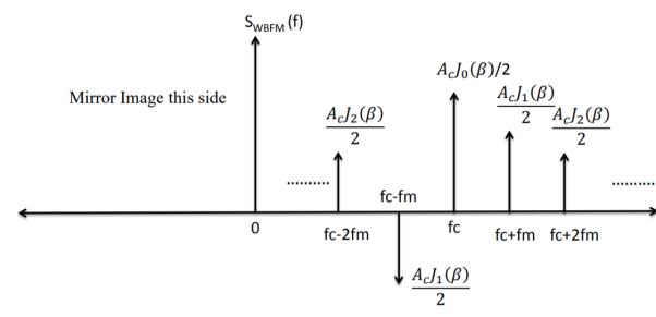
Figure 7. Spectrum of Wideband FM
Key Takeaways:
- Narrow Band FM derivation and spectrum
- Wideband FM derivation and spectrum
- Armstrong method of FM generation is the indirect method because the modulating signal directly varies the phase of the carrier, which indirectly changes the frequency.
- The Fig1 shows the block diagram of wideband FM generation through Armstrong method.
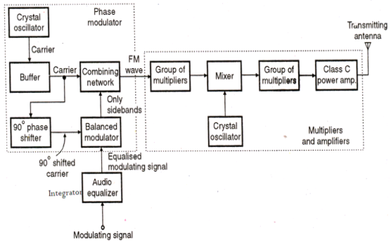
Figure 8. Armstrong frequency modulation system
- The source of carrier for the Armstrong transmitter is the crystal oscillator. A relatively low frequency sub-carrier (fcfc) is phase shifted by 90° and is fed to a balanced modulator, where it is mixed with the input modulating signal (fmfm).
- A double sideband suppressed carrier wave is produced at the output from the balanced modulator, and this is combined with the original carrier in the combing network to generate a narrow band frequency modulated waveform.
- The phasor diagrams in Fig illustrate the working of this modulation system. Fig. (a) shows the phasor diagram for the original carrier voltage (Vc), (b) shows phasor of the phase shifted carrier (V′c′), (c) shows phasors for side frequency components of the suppressed carrier voltage 〖(V〗_usb) and (Vlsb). Since the suppressed carrier voltage (V′c′) is 90° out of phase with (Vc), the upper and lower sidebands combine to produce a component (VmVm) which is always perpendicular to (Vc). The Fig (d) shows phasor addition of (Vc), (Vusb) and (Vlsb) which is the resultant of the combining network.
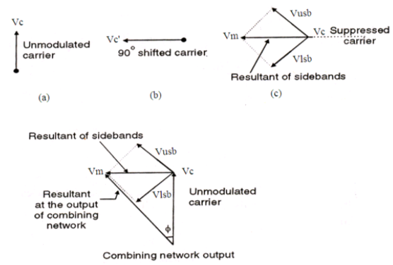
Figure 9. Phasor diagrams (a) carrier phasor, (b) phase shifted carrier, (c) sideband phasors, (d) resultant phasor
- It is seen that the output from the combing network is a signal whose phase is varied by fm and magnitude is directly proportional to the magnitude of Vm.
- The modulation index at the output of the combining network is inadequate to produce a wideband FM and therefore must be multiplied and amplified before transmitting.
- A combination of multipliers and mixers are thus placed to develop the desired transmit carrier frequency with 75 kHz frequency deviation.
- The outcome of the mixer block is the change in the center frequency, while the outcome of the multiplier block is the multiplication of the center frequency and the frequency deviation equally. Hence a narrow band FM with small frequency deviation is transformed into a wide band FM with large frequency deviation.
- In the Armstrong method of FM generation, the phase of the carrier is directly modulated in the combing network through summation, generating indirect frequency modulation. The magnitude of the phase deviation is directly proportional to the amplitude of the modulating signal but independent of its frequency.
- Very high frequency stability is achieved through Armstrong method since the crystal oscillator is used as carrier frequency generator.
Key Takeaways:
1.Method of FM generation
2. Phasor diagram
Frequency multiplier is a non-linear device, which produces an output signal whose frequency is ‘n’ times the input signal frequency. Where, ‘n’ is the multiplication factor.
• If NBFM wave whose modulation index β is less than 1 is applied as the input of frequency multiplier, then the frequency multiplier produces an output signal, whose modulation index is ‘n’ times β and the frequency also ‘n’ times the frequency of WBFM wave.
• Sometimes, we may require multiple stages of frequency multiplier and mixers in order to increase the frequency deviation and modulation index of FM wave.

Figure 10. Frequency Multiplier
When NBFM is passed through Frequency multiplier WBFM is obtained.
• The output of the NBFM oscillator is
S NBFM(t) = Ac cos[ 2πfct+ β sin 2πfmt]
Where β is very less than 1
The output of frequency multiplier with multiplying factor n is wide band FM that is
S WBFM (t) = Ac cos[n(2πfct + β sin 2πfmt)]
S WBFM(t) = Ac cos[2πnfct + nβ sin 2πfmt]
S WBFM(t) = Ac cos[ 2π fc’t + β’ sin 2πfmt]
An FM is given by:
𝑆(t)=10 cos[2𝜋 × 106𝑡 + 0.2𝑠in4𝜋 × 103𝑡]
It is passed through cascaded frequency multiplier having multiplying constant of 4 and 5 respectively.
Find all the parameters of FM signal at the output of each of the multiplier. (Ac, 𝛽, fc, fm, ∆𝑓, bandwidth, power)

𝑆(t)=10 cos[2𝜋 × 106𝑡 + 0.2𝑠in4𝜋 × 103𝑡]
Compare with the standard equation
S FM(t) = Ac cos[2πfct+ β sin 2πfmt]
Ac = 10V, β=0.2,fc=1MHz, fm=2KHz, ∆f= β Fm = 0.4 KHz
After passing through first multiplier (n=4)
Ac’ = 10V
β ‘= 4 x0.2 = 0.8
Fc’ = 4x1 = 4Mhz
Fm’ = 2KHz
∆f ‘= βfm = 4 x 0.4Khz = 1.6 KHz
BW = 2fm = 2x2=4Khz
Power = Ac2/2[ 1 + β 2 /2] = 66W
After passing through second multiplier (n=5)
Ac’” = 10V
β “‘= 5 x0.8 = 4
Fc’’ = 4x5 = 20Mhz
Fm’ = 2KHz
∆f ‘’ = n ∆f’ = 5 x 1.6= 8 KHz
BW = 2(1+β)fm = 2x5x2=20Khz
Power = Ac2/2R = 50W
Applications:
- Frequency modulation can be used for the broadcasting of FM radio. This helps in larger signal to noise ratio.
- Telemetry, radar and seismic prospecting, EEG monitoring of new-borns etc also use the technique of frequency modulation.
- It is also used in music synthesis, some systems that use video-transmission and also for magnetic tape-recording systems.
FM demodulator:
In order to be able to demodulate FM, a receiver must produce a signal whose amplitude varies as according to the frequency variations of the incoming signals and it should be insensitive to any amplitude variations in FM signal.
Insensitivity to amplitude variations is achieved by having a high gain IF amplifier. Here the signals are amplified to such a degree that the amplifier runs into limiting. In this way any amplitude variations are removed. Generally, a FM demodulator is composed of two parts:
Discriminator and Envelope Detector
Discriminator is a frequency selective network which converts the frequency variations in an input signal in to proportional amplitude variations. Hence when it is input with an FM signal, it can produce an amplitude modulated signal. But it does not generally alter the frequency variations which were there in the input signal. So, the output of a discriminator is a both frequency and amplitude modulated signal. This signal can be fed to the Envelope Detector part of FM demodulator to get back the baseband signal.
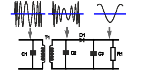
Figure 11. Slope detector
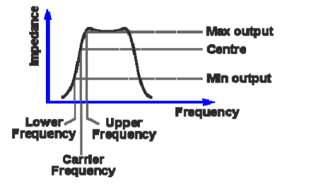
Figure 12. Frequency response of slope detector
Slope detector: A very simplest form of FM demodulation is known as slope detection or demodulation. It consists of a tuned circuit that is tuned to a frequency slightly offset from the carrier of the signal.As the frequency of the signals varies up and down in frequency according to its modulation, so the signal moves up and down the slope of the tuned circuit. This causes the amplitude of the signal to vary in line with the frequency variations. In fact, at this point the signal has both frequency and amplitude variations.It can be seen from the diagram that changes in the slope of the filter, reflect into the linearity of the demodulation process.The linearity is very dependent not only on the filter slope as it falls away, but also the tuning of the receiver - it is necessary to tune the receiver frequency to a point where the filter characteristic is relatively linear. The final stage in the process is to demodulate the amplitude modulation and this can be achieved using a simple diode circuit. One of the most obvious disadvantages of this simple approach is the fact that both amplitude and frequency variations in the incoming signal appear at the output. However, the amplitude variations can be removed by placing a limiter before the detector. The input signal is a frequency modulated signal. It is applied to the tuned transformer (T1, C1, C2 combination) which is offset from the centre carrier frequency. This converts the incoming signal from just FM to one that has amplitude modulation superimposed upon the signal. This amplitude signal is applied to a simple diode detector circuit, D1. Here the diode provides the rectification, while C3 removes any unwanted high frequency components, and R1 provides a load.
Key Takeaways:
- Frequency multiplication and its applications
- FM demodulator
References:
Digital Communication Systems Book by Simon S. Haykin
Principles of digital communication Textbook by Robert G. Gallager
Digital Communications Book by John G Proakis and Masoud Salehi
Digital Communications Book by Sanjay Sharma
Digital Communication Book by J.S.Chitode