Unit 6
Baseband Digital Transmission
A line code is the code used for data transmission of a digital signal over a transmission line. This process of coding is chosen so as to avoid overlap and distortion of signal such as inter-symbol interference.
Properties of Line Coding
- As the coding is done to make more bits transmit on a single signal, the bandwidth used is much reduced.
- For a given bandwidth, the power is efficiently used.
- The probability of error is much reduced.
- Error detection is done and the bipolar too has a correction capability.
- Power density is much favourable.
- The timing content is adequate.
- Long strings of 1s and 0s is avoided to maintain transparency.
Types of Line Coding
There are 3 types of Line Coding
- Unipolar
- Polar
- Bi-polar
Unipolar Signalling
Unipolar signalling is also called as On-Off Keying or simply OOK.
The presence of pulse represents a 1 and the absence of pulse represents a 0.
There are two variations in Unipolar signalling −
- Non- Return to Zero NRZ
- Return to Zero RZ
Unipolar Non-Return to Zero NRZ
In this type of unipolar signalling, a High in data is represented by a positive pulse called as Mark, which has a duration T0 equal to the symbol bit duration. A Low in data input has no pulse.
The following figure clearly depicts this.
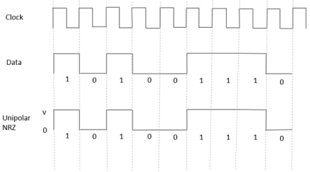
Figure 1. NRZ format
Advantages
The advantages of Unipolar NRZ are −
- It is simple.
- A lesser bandwidth is required.
Disadvantages
The disadvantages of Unipolar NRZ are −
- No error correction done.
- Presence of low frequency components may cause the signal droop.
- No clock is present.
- Loss of synchronization is likely to occur (especially for long strings of 1s and 0s).
Unipolar Return to Zero RZ
In this type of unipolar signalling, a High in data, though represented by a Mark pulse, its duration T0 is less than the symbol bit duration. Half of the bit duration remains high but it immediately returns to zero and shows the absence of pulse during the remaining half of the bit duration.
It is clearly understood with the help of the following figure.
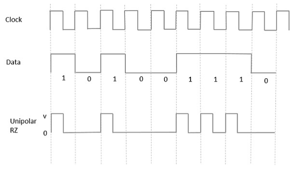
Figure 2. RZ format
Advantages
The advantages of Unipolar RZ are −
- It is simple.
- The spectral line present at the symbol rate can be used as a clock.
Disadvantages
The disadvantages of Unipolar RZ are −
- No error correction.
- Occupies twice the bandwidth as unipolar NRZ.
- The signal droop is caused at the places where signal is non-zero at 0 Hz.
Polar Signalling
There are two methods of Polar Signalling. They are −
- Polar NRZ
- Polar RZ
Polar NRZ
In this type of Polar signalling, a High in data is represented by a positive pulse, while a Low in data is represented by a negative pulse. The following figure depicts this well.
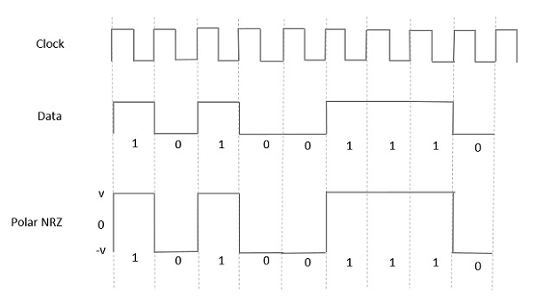
Figure 3. Polar NRZ
Advantages
The advantages of Polar NRZ are −
- It is simple.
- No low-frequency components are present.
Disadvantages
The disadvantages of Polar NRZ are −
- No error correction.
- No clock is present.
- The signal droop is caused at the places where the signal is non-zero at 0 Hz.
Polar RZ
In this type of Polar signalling, a High in data, though represented by a Mark pulse, its duration T0 is less than the symbol bit duration. Half of the bit duration remains high but it immediately returns to zero and shows the absence of pulse during the remaining half of the bit duration.
However, for a Low input, a negative pulse represents the data, and the zero level remains same for the other half of the bit duration. The following figure depicts this clearly.
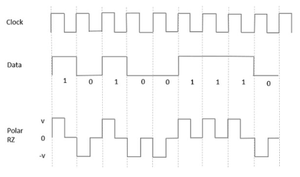
Figure 4. Polar RZ
Advantages
The advantages of Polar RZ are −
- It is simple.
- No low-frequency components are present.
Disadvantages
The disadvantages of Polar RZ are −
- No error correction.
- No clock is present.
- Occupies twice the bandwidth of Polar NRZ.
- The signal droop is caused at places where the signal is non-zero at 0 Hz.
Bipolar Signalling
This is an encoding technique which has three voltage levels namely +, - and 0. Such a signal is called as duo-binary signal.
An example of this type is Alternate Mark Inversion AMIAMI. For a 1, the voltage level gets a transition from + to – or from – to +, having alternate 1s to be of equal polarity. A 0 will have a zero-voltage level.
Even in this method, we have two types.
- Bipolar NRZ
- Bipolar RZ
From the models so far discussed, we have learnt the difference between NRZ and RZ. It just goes in the same way here too. The following figure clearly depicts this.
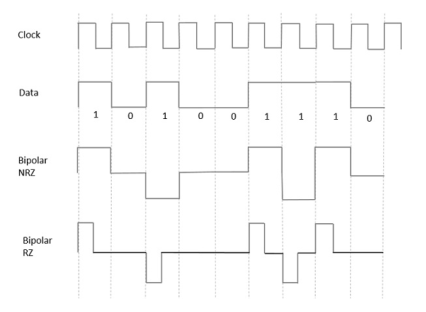
Figure 5. Bipolar NRZ and RZ
The above figure has both the Bipolar NRZ and RZ waveforms. The pulse duration and symbol bit duration are equal in NRZ type, while the pulse duration is half of the symbol bit duration in RZ type.
Advantages
Following are the advantages −
- It is simple.
- No low-frequency components are present.
- Occupies low bandwidth than unipolar and polar NRZ schemes.
- This technique is suitable for transmission over AC coupled lines, as signal drooping doesn’t occur here.
- A single error detection capability is present in this.
Disadvantages
Following are the disadvantages −
- No clock is present.
- Long strings of data causes loss of synchronization.
Key Takeaways:
- Line codes and its properties
- Line codes spectrum
Multiplexing is a technique which integrates several signals and transmits it over a single data link. These multiplexed signals are accepted by the demultiplexer which separates them and delivers them to the corresponding node. Multiplexing makes the transmission of multiple signals, economical as we do not have to add a new link for each new signal.
Multiplexing can be performed on analog as well as digital signals. For analog signals, multiplexing has two variations i.e. frequency division multiplexing (FDM) and wavelength division multiplexing (WDM). And on digital signals, time division multiplexing is performed.
TI, AT & T, EI, CCITT, Scrambling and Unscrambling
E1/T1:
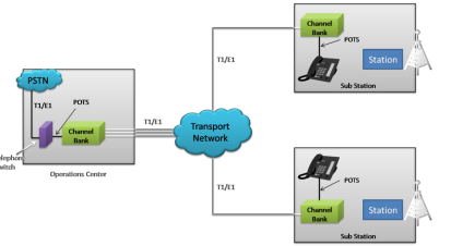
Figure 6. EI/TI
T1 – developed by AT&T used in America provides 1.544Mbps communication link
E1-used in Europe provides 2.048 Mbps communications link
Belong to first two layers of OSI- physical and data link layers
Uses time division multiplexing to “slice up” data and assign time slots for transmissions.
CCITT:
The CCITT, now known as the ITU-T (for Telecommunication Standardization Sector of the International Telecommunications Union), is the primary international body for fostering cooperative standards for telecommunications equipment and systems
AT &T:
AT&T Communications, LLC is a subsidiary of AT&T that focuses on digital television, satellite television, fixed line telephone, mobile phone, broadband, home security, IPTV, OTT (Over The Top) services, network security, and pay television offerings, business applications.
Scrambling and Unscrambling:
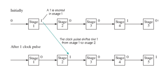
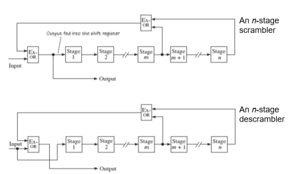
Figure 7. Scrambling and Unscrambling
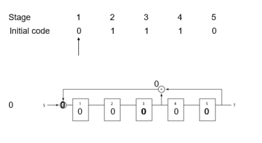
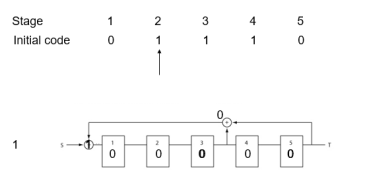
Figure 8. Stages of coding
Set/Reset Scrambling:
Sending
Combining the input data with a PRBS in an exclusive-OR gate.
Receiving
Combining, in an exclusive-OR gate, the coded data with the identical pseudo-random sequence used at the transmitter,
synchronization.
Frame alignment must take place
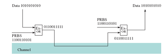
Figure 9. Set/Reset Scrambling
Key Takeaways:
- Multiplexing
- Scrambling and Unscrambling
Carrier Synchronization:
In digital communication systems data is not send as a simple stream of bits or bytes but in terms of frames or packets. So, the receiver must be able to recognize the start of the frame by process called frame synchronization. Generally, there are three levels of synchronization in a complete communication system: carrier synchronization, symbol synchronization, frame synchronization. Carrier synchronization refers to the process of generating a reference carrier with frequency and phase that is close to frequency and phase of a received carrier. Symbol carrier refers to the process of deriving timing signals at the receiver which indicate where, in time, the transmitted symbols are located. Once symbol synchronization is accomplished, the next synchronization level is frame synchronization.
Bit Synchronization:
For synchronous transmission, data is not transferred byte-wise so there are no start or stop bits indicating the beginning or end of a character. Instead, there is a continuous stream of bits which have to be split up into bytes. Therefore, the receiver has to sample the received data in the right instant and the sender's and receiver's clocks have to be kept in a synchronized state. As the main task lies in synchronizing sender's and receiver's clocks, bit synchronization is also called clock synchronization.
Frame Synchronization:
Frame synchronization is the method used by receiver to locate the time position of the start of the frame i.e., the receiver needs a frame synchronization process to know where each frame of the transmitted frames starts in order to demodulate the transmitted data. This process is achieved in several steps. First, the transmitter inserts a fixed length symbol pattern called a marker into the beginning of each frame to form a marker and frame pair, which is known as a packet. Packets are then converted from symbols into a waveform and transmitted through the channel. The receiver detects the arrival of packets by searching for the marker, then removes the markers from the data.
Inter symbol Interference:
Let us consider the transmission of a sequence of symbols with the basic waveform u(t). To send the nth symbol bn, we send bn u(t -nT ), where T is the symbol interval. Therefore, the transmitted signal is
 u(t-nT) ---------------------------------------------------------------(1)
Based on the dispersive channel model the received signal is given by
r(t) =  u(t-nT) + n(t) -----------------------------------------------------(2)
Where v(t) = u hc(t) is the received waveform for a symbol. If a single symbol, say the symbol b0, is transmitted, the optimal demodulator is the one that employs the matched filter, i.e., we can pass the received signal through the matched filter v~(t) = v(t) and then sample the matched filter output at time t = 0 to obtain the decision statistic.
When a sequence of symbols is transmitted, we can still employ this matched filter to perform demodulation. A reasonable strategy is to sample the matched filter output at time t = mT to obtain the decision statistic for the symbol bm. At t = mT, the output of the matched filter
Zm =  v *
v *  (mT-nT) + nm
= bm ||v|| 2 +  v *
v *  (mT-nT) + nm ------------------------------------------------(3)
Where nm is a zero-mean Gaussian random variable with variance N0kvk2=2. The first term in (3) is the desired signal contribution due to the symbol bm and the second term contains contributions from the other symbols. These unwanted contributions from other symbols are called inter symbol interference.
Equalization:
For many physical channels, such as telephone lines, not only are they bandlimited, but they also introduce distortions in their passbands. Such a channel can be modelled by an LTI filter followed by an AWGN source as shown in Figure(a). This is the dispersive channel model. In general, ISI is often introduced. For a communication system employing a linear modulation, such as BPSK, through a dispersive channel, the whole system can be described as the conceptual model.

Figure 10. Equalization
In which the sequence of information symbols is denoted by fIkg and HT (f ), HC (f ), and HR(f ) are the transfer functions of the transmission (pulse-shaping) filter, the dispersive channel and the receiving filter, respectively.
Letting X(f ) = HT (f )HC(f )HR(f ), the condition for no ISI is that the folded spectrum X(f ), is constant for all frequencies, i.e.,
 =T---------------------------------------------(1)
One method to achieve the Nyquist condition is to fix the receiving filter to be the matched filter, i.e., set HR(f ) = HT (f )HC (f ), and choose the transmission filter so that eq(1) is satisfied.
. The major disadvantage of this pulse shaping method is that it is in general difficult to construct the appropriate analog filters for HT (f) and HR (f) in practice. Moreover, we have to know the channel response Hc (f) in advance to construct the transmission and receiving filters. An alternative method is to fix the transmission filter4 and choose the receiving filter HR(f ) to satisfy the condition in eq(1) As for the previous method, it is also difficult to build the appropriate analog filter HR(f ) to eliminate ISI. However, notice that what we want eventually are the samples at intervals T at the receiver. Therefore, we may choose to build a simpler (practical) filter HR(f ), take samples at intervals T , and put a digital filter, called equalizer, at the output to eliminate ISI as shown below in Figure (b). This approach to remove ISI is usually known as equalization.

Figure11. Communication system with equalizer
Key Takeaways:
- Carrier synchronization
- Bit synchronization
- Equalization
- Inter symbol interference
- Frame Synchronization
References:
Digital Communication Systems Book by Simon S. Haykin
Principles of digital communication Textbook by Robert G. Gallager
Digital Communications Book by John G Proakis and Masoud Salehi
Digital Communications Book by Sanjay Sharma
Digital Communication Book by J.S.Chitode