Unit - 1
Electrostatics
Electromagnetics (EM) may be regarded as the theory of interactions between the electric charges at rest and in motion. Electromagnetics is a branch of physics or electrical engineering in which electric and magnetic phenomena are studied. It involves the analysis, physical interpretation and application of electric and magnetic field.
EM principles find its applications in antennas, electric machines, satellite communications, fiber optics, electromechanical energy conversion, remote sensing etc.
EM devices include transformers, electric relays, radio/TV, telephones, electric motors, transmission lines, antennas, optical fibers, radars, and lasers. The design of these devices are in accordance with the laws and principles of EM.
Review of 3D Coordinate Geometry
A co-ordinate system represents a way of specifying the location of any position in space with respect to origin.
The point is defined by the intersection of three mutually perpendicular surfaces. The coordinate axes are defined by the normal to these surfaces at the point.
Rectangular or Cartesian coordinates
The coordinate system is defined by the intersection of three mutually perpendicular planes as shown in figure2.
The lines parallel to the lines of intersection between the planes define coordinate axes (x, y, z).
x-axis lies perpendicular to the plane of constant x.
y-axis lies perpendicular to the plane of constant y.
z-axis lies perpendicular to the plane of constant z.
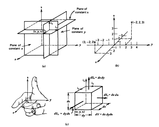
Figure. Cartesian coordinate system. (a) Intersection of three mutually perpendicular planes defines the Cartesian coordinates (x, y, z). (b) A point is located in space by specifying its x-, y- and z-directed distances from the origin. (c) Differential volume and surface area elements.
In a right-handed coordinate system is used where one curls fingers of his/her right hand in the direction from x to y direction. Forefinger represents x direction, middle finger y direction, and thumb points z direction.
The coordinate directions are represented by unit vectors ix, iy, iz each of which has unit length and points in the direction along one of the coordinate axes.
Rectangular coordinates are the simplest because unit vectors always point in same direction.
A rectangular differential volume is formed when one moves from a point (x, y, z) by incremental distance dx, dy, dz in each of three coordinate directions.
Cylindrical coordinates:
The circular cylindrical co-ordinate system is a three-dimensional version of polar co-ordinate system. The surfaces used to define the cylindrical co-ordinate system are:
- Plane of constant z which is parallel to xy plane.
- A cylinder of radius r with z-axis of the cylinder
- A half plane perpendicular to xy plane at angle Ø with respect to xz plane. The angle Ø is called the azimuth angle.
The ranges of the variable are:
0 ≤ r ≤ ∞------------------(1)
0 ≤Ø≤ 2π------------------------------(2)
-∞≤z≤∞--------------------------------------------------(3)
The point P in cylindrical co-ordinate system has three co-ordinates r, Ø and z whose values lie in the ranges given by equations 1,2,3.
The point P(r,Ø1,z1) can be shown in figure (b)
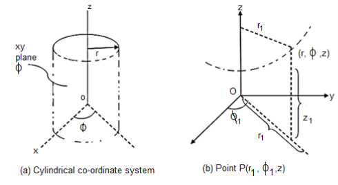
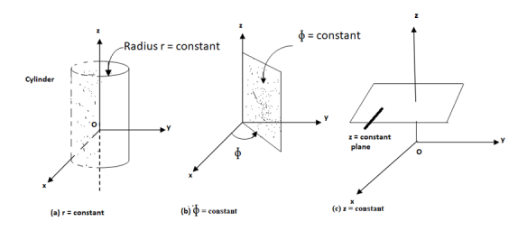
The point P can be defined as the intersection of three surfaces in cylindrical co-ordinate system. These three surfaces are,
r = Constant which is circular cylinder with z axis as its axis
Ø= Constant plane which is a vertical plane perpendicular to xy plane making angle Ø with respect to xz plane.
z= Constant plane is a plane parallel to xy plane.
These surfaces are shown in figure.
Spherical co-ordinate system:
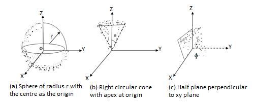
The surfaces which are used to define the spherical co-ordinate system on the three cartesian axes are:
- Sphere of radius r, origin as the centre of the sphere.
- A right circular cone with its apex at the origin and its axis as z-axis. It half angle is Ѳ varies from 0 to 180.
- A half plane perpendicular to xy plane containing z axis making an angle Ø with xz plane.
Thus the three co-ordinates of a point P in the spherical co-ordinate system are (r,Ѳ,Ø). These surfaces are shown in figure
The ranges of the variables are 


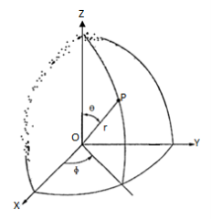
The point P(r,Ѳ,Ø) can be represented in the spherical co-ordinate system as shown in figure. The angles Ѳ and Ø are measured in radians. The point P can be defined as the intersection of three surfaces in spherical co-ordinate system. These three surfaces are:
r= constant whichis a sphere with centre as origin.
 =Constant which is rigid circular cone with apex as origing and axis as z axis.
 Constant is a plane perpendicular to xy plane.
- Addition
- Addition is commutative:
 +
+ =
= +
+
- It is also commutative: (
 +
+ ) +
) +  = (
= (

 +
+ =
= 
2. Subtraction
 -
- =
=  +
+
- It does not follow commutative law:

But follows associative law


-ve sign shows reversal of direction
3. Multiplication
- Dot Product or Scalar Product


Dot product of vector is scalar
- Vector or Cross Product
 =
=  î
î
î = unit vector in the direction of perpendicular to 
To find direction î, use right hand screw rule.
Cross Product of two vector is always a vector


- A vector multiplied/divided by a scalar
 = it increases the magnitude by s unit
 = it decreases the magnitude by s unit
 = it does not exist
Consider that in space let W be the unique function of x, y, z co-ordinates in the cartesian system. This is scalar function denoted as W (x, y, z). Consider the vector operator in cartesian system denoted as  called del. It is defined as

Grad W =W=

The gradient of a scalar W in various co-ordinate systems are given by,
S.No Co-ordinate system Grad W=W
1. Cartesian 
2. Cylindrical 
3. Spherical 
Properties:
The various properties of a gradient of a scalar field W are:
- The gradient
 W gives the maximum rate of change of W per unit distance
 - The gradient
 W always indicates the direction of the maximum rate of ch W.
 - The gradient
 W at any point is perpendicular to the constant W surface passes through the point.
 - The directional derivative of W along the unit vector
 is W
is W  (dot product which is the projection of
  W always indicates the direction of maximum rate of ch W.
U is another scalar function then


Problem:
A scalar field is given by
a)  … In Cartesian
b)  … In cylindrical
c)  … In spherical
Find its gradient at P(0,1,1) for cartesian,  for cylindrical and
  for the spherical.
a)  in Cartesian


 At P (0,1,1) the

 in cylindrical.
 =
=


At  the =
the =
 gives the flux flowing across surface S. Then mathematically divergence is defined as the net outward flow of the flux per unit volume over a closed incremental surface. It is denoted as div
  given by
 Divergence of
 Differential volume element
Symbolically it is denoted as,
 Divergence of
Where =Vector operator =
But 

This is divergence of  in Cartesian system.
Similarly, divergence in other co-ordinate systems are,
 cylindrical
 spherical
Physically divergence at a point indicate how much that vector field diverges from that point.
Consider a sloenoid that is the elctromagnet obtained by winding a coil around the core. When current passes through it flux produced around it. Such a flux completes a closed path through the solenoid hence solenoid field does not diverge. Therefore the vector field having its divergence zero is called solenoidal field.
 for
for  to be solenoidal
The circulation of a vector field around closed path is given by curl of vector. Mathematically it is defined as
Curl of 
Where  Area enclosed by the line integral in normal direction
Thus, maximum circulation of  per unit area tends to zero whose direction is normal to the surface is called curl of
  .
.
Symbolically it is represented as 
In various co-ordinate system, the curl of  is given by,

 (3)
(3)

 Cylindrical
In  r cannot be taken outside as differential is with respect to

 Spherical
Theorem and applications:
The Stoke’s theorem relates to the line integral to a surface integral. It states that the line integral of  around a closed path L is equal to the integral of curl of
  over the open surface S enclosed by the closed path L.
Mathematically it is expressed as

Where
 (1)
(1)
Where dL=Perimeter of total surface S
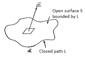
Problem: Verify Stoke’s theorem

Around the path L defined by 
As shown in figure.
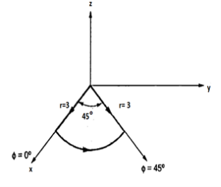
Solution:
From Stoke’s theorem

To LHS of Stoke’s theorem is already evaluated in Ex. 1.18 which is 2.636.
To evaluate R.H.S find × 
× 


 as surface is in x-y plane i.e., z=0 plane for which normal direction is

Thus, Stoke’s theorem is verified.
Problem: Given points  and
and  in
in
Cylindrical co-ordinate system. Find
i) Unit vector in Cartesian co-ordinates at P directed towards Q.
Ii) Unit vector in Cylindrical co-ordinates at P directed towards Q.
Solution:
Let us obtan the cartesian co-ordinates of P and Q.
It is known that x=r cos , y=r sin and z=z
 and
and 
i) the unit vector from P to Q is,
 where
where  and
and  are position vectors


(ii)
The vector 
Let us transform this into cylindrical coordinates.


At point 


Problem: Find the divergence and curl of the following function:

Solution


Problem: F (x, y)=(x2+xy)ax+(y2+xy)ay. Calculate its line integral over the straight line from (x, y) = (0,2) to (2,0).
Solution:
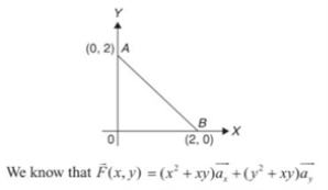
Consider the figure given above
Along the straight line for A (0,2) to B (2,0), slope of the line AB= .
.
Equation of the line, AB will be 
For 


= 8
Consider a point charge Q1 as shown in figure:
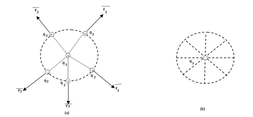
If any other similar charge Q2 is brought near it Q2 experiences a force. Infact if Q2 is moved around Q1 still Q2 experiences a force as shown in figure.
Thus, there exists a region around a charge in which it exerts force on any other charge. This region where a particular charge exerts a force on any other charge located in that region called electric field of that charge. The electric field of Q1 is shown in figure (b).
The force experienced by the charge Q2 due to Q1 is given by Coulombs law as,

Thus, force per unit charge can be written as:

This force exerted per unit charge is called electric field intensity or electric field strength. It is a vector quantity and is directed along a segment from the charge Q1 to the position of any other charge.
It is denoted as  .
.
Another definition of electric field is the force experienced by a unit positive test charge that is Q2 = 1C.
Consider a charge Q1 as shown in figure below. The unit positive charge Q2=1C is placed at distance R from Q1. Then the force acting on Q2 due to Q1 is along the unit vector  As the charge Q2 is unit charge the force exerted on Q2 is nothing but electric field intensity
  of Q1. Then the force acting on Q2 due to Q1 is along the unit vector
  As the charge Q2 is unit charge the force exerted onQ2 is nothing but electric field intensity
  of Q1 at a point where unit charge is placed.
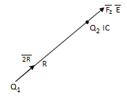
Concept of electric field intensity

If a charge Q1 is located at the center of the spherical coordinate system then unit vector  in equation (3) becomes the radial unit vector
  coming radially outwards from Q1 and the distance R is the radius of the sphere r.
Problem:
The electric field E (in V/m) at the point (1,1,0) due to a point charge of +1 C located at (-1,1,1) (co-ordinates in meters) is
(a)  (b)
(b)  (c)
(c)  (d)
(d) 
Solution: (a)
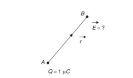
Point B= ( =B (1,1,0)
Point B= ( =B (1,1,0)
Position vector


Magnitude of position vector


The required electric field will be

Electric displacement refers to the displacement of electric charge across a conductor positioned in an electric field. It measures the charge per unit area, and it is also called as electric flux density.
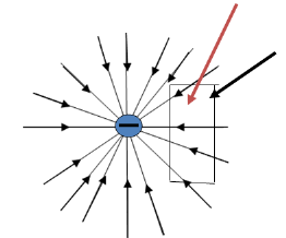
The electric flux density is always tangential to electric flux lines. Electric flux lines originate from a positive charge and ends on a negative charge.
D= Flux/Area
 and
and 

 : Electric Flux Density C/m2
 : Electric Field Intensity V/m
 : Free Space Permittivity = 8.854 x 10⁻¹² F/m
Electric Field  depends on the medium where as
  is independent of the medium.
Definition:
The electric flux passing through any closed surface is equal to the total charge enclosed by that surface.
The total charge enclosed by the irregular closed surface is Q coulombs. Hence the total flux has to pass through the closed surface is Q. Consider a small differential surface dS at point P. As the surface is irregular the direction of D as well as its magnitude is going from point to point on the surface. The surface dS under consideration can be represented in vector form.

Where  to the surface dS at point P
The flux density at point P is D and its direction is such that it makes an angle Ѳ with the normal direction at point P.
The flux d passing through the surface dS is the product of the component normal to dS and d
 .
.
Mathematically this can be represented as,

Where  Component of
  in the direction of normal to the surface dS
From fig. 3.9 we can write


From the definition of the dot product

We can write


This is the flux passing through incremental surface area dS. Hence the total flux passing through the entire closed surface is to be obtained by finding the surface integration of the equation (5)

 sign indicates the integration over the closed surface is called closed surface integral.
Such a closed surface over which the integration in eq (6) is carried out is called Gaussian surface.
Total charge enclosed by the surface is given by

Applications:
Infinite line charge:
Consider an infinite line charge of density  C/m lying along the z-axis from -
  to
to  as shown in figure.
Consider the Gaussian surface as the right circular cylinder with z-axis as its axis and radius r as shown in figure. The length of the cylinder is L.
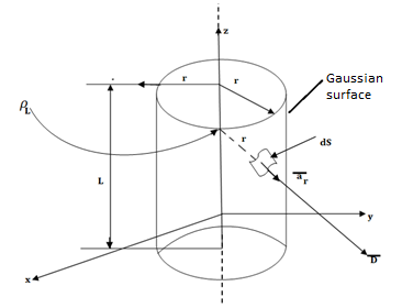
Infinite Line charge
The flux density at any point on the surface is directed radially towards that is in the  direction according to cylindrical co-ordinate system.
Consider differential surface area dS as shown which is at a radial distance r from the line charge. The direction is normal to dS is 
As the line charge is along z-axis there cannot be any component D in z direction. So, D has only radial component.

The integration is to be evaluated for side surface, top surface and bottom surface.

Now  as has only radial component
And  normal to
  direction.
 … as
… as 
Now  is constant over the side surface.
As  has only radial component and no component along
  and
and  hence integrations over top and bottom surfaces is zero.


And 
The results are same as obtained from the Coulomb’s law.
Consider an electric field due to positive charge. If a unit test positive charge Q1 is placed at any point in this field it experiences a repulsive force and tends to move in the direction of the force.
If a positive test chargeQ1 is to be moved towards the positive base charge Q then it is required to be moved against the electric field of the charge Q that is against repulsive force exerted by charge Q on the test charge. While doing so an external source has to do work to move test charge Qt against electric fields. This movement of charge requires to expend the energy. This work done becomes the potential energy of the test charge Qt at the point at which it is moved.
Thus, work is said to be done when the test charge is moved against the electric field.
In a uniform field, electric field lines are parallel and equidistant to each other. An example is a pair of two plates, one at 0 V, other at +500 V. The field lines in between are parallel. The equipotential decreases linearly as distance from source charge decreases. In a non-uniform electric field, the field lines are not parallel and not equidistant. An example is a single proton, with field lines that are “circle outwards”. The equipotential decreases by an inverse square law by increase in distance from source charge.
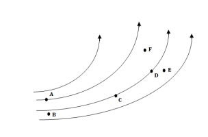
Utilization factor η =The mean electric field/ The maximum electric field
The electrical potential difference is determined by V (r) = -
Where E(r) is the electric field intensity. We can also find the electric field at any point r if we can describe V as a function of r.
DV=−E(r)⋅dl
In Cartesian coordinates, dl=
For any scalar function of position, including V(r), it is true that

Also note that  and so on for dy and dz


Note that the quantity in square brackets is the gradient operator “∇”

This relationship between V and E has a useful physical interpretation. The electric field points in the direction in which the electric potential most rapidly decreases.
Electric fields due to continuous charge distributions
It is also possible to have continuous charge distribution along a line, on a surface, or in a volume. It is important to denote the line charge density, surface charge density, and volume charge density by  L (in C/m),
  s (in C/m2), and
  v (in C/m3) respectively.
 (Line charge)
 (Surface charge)
 (Volume charge)
A. A Line Charge
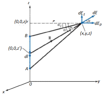
Consider a line charge with uniform charge density  extending from A to B along the z-axis as shown in figure. The charge element dQ associated with element dl = dz of the line is
DQ =  dl =
dl =  dz
dz
And hence the total charge Q is –

The electric field intensity E at an arbitrary point P (x, y, z) can now be calculated
The field point is denoted by (x, y, z) and the source point by (x', y ', z ').
R = (x, y, z) - (0, 0, z') = xax + yay + (z - z')az
Since  and by replacing Q by dq for line charge and integrating,
We get  where aR =


Substituting all this into

Also 

Hence for a finite line charge,

As a special case, for an infinite line charge, point B is at (0, 0,  ) and A at
(0, 0, -  ) so that
  =
= ,
,  = -
= - ; the z-component vanishes and hence
E= 
If the line is not along the z-axis,  is the perpendicular distance from the line to the point of interest, and ar is a unit vector along that distance directed from the line charge to the field point.
Note: In the above formula  can be replaced by
  and
and  with l also.
B. A SURFACE CHARGE
Consider an infinite sheet of charge in the xy-plane with uniform charge density  . The charge associated with elemental area dS is: dQ=
 dS
dS
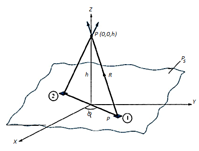
The contribution to the E field at point P (0, 0, h) by the charge dQ on the elemental surface 1 shown in figure is:

From the figure:


Substituting the following terms in the expression of dE,

Because of the symmetry of the figure E has only one component that is in the z direction and integration of sin over 0<
 < 2
< 2 is 0. Hence:


E has only z component if the sheet is in x-y plane and this is valid for only h>0. If
h<0 then az will be replaced by –az since h<0.
In general, for an infinite sheet of charge E=  an, where an is a normal vector to the sheet. The electric field is normal to the sheet and is independent of the distance between the sheet and point of observation.
C.A VOLUME CHARGE
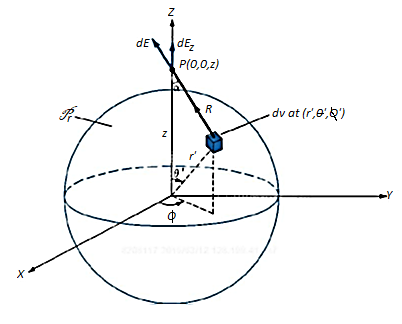
Let us consider a sphere of radius ‘a’ centered at the origin. Let the volume of the sphere be filled uniformly with a volume-charge density  (in C/m3). The charge dQ associated with the elemental volume dv chosen at (
 ',
',  ',
',  ') is
') is

And hence the total charge in a sphere of radius a is

The electric field dE outside the sphere at P (0, 0, z) due to the elementary volume charge is
 =
= 
Where aR = cos az + sin
 a
a , the contributions to Ex or Ey add up to zero. We are left with only EZ given by

We need to derive expressions for dv, R and cos :
:

Applying the cosine rule to the above figure:


Differentiating cos with respect to
  and keeping z and r’ fixed
Sin ( ) d (
) d ( =
= 
Because Point of Observation P lies outside the sphere  varies from 0 to π, R varies from (z-r’) to (z+r’)


Or 
This result is obtained for E at P (0,0, z) and because of the symmetry of the charge distribution, the electric field at P (r,  ,
, ) is given by

Problem: A solid sphere made of insulating material has a radius R and has a total charge Q distributed uniformly in its volume. What is the magnitude of the Electric Field intensity, E, at distance r (0< r < R) inside the sphere?
Solution:
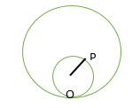
Consider a Point P inside the sphere at a distance r from the centre O as shown in the figure. Total charge inside the sphere of radius r is:
 =
= 
If we consider a spherical Gaussian surface, passing through P, then by applying Gauss’s Law:

D(4 r2) =
r2) = 
E =  = Q
= Q 
E = Q  N/C
N/C
Problem: Identical charges q are placed at five vertices of a regular hexagon of side L. Calculate the magnitude of the electric field and the electrostatic potential at the centre of the hexagon.
Solution:
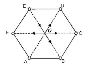
The electric field at the centre is only due to charge q placed at A. Since the resultant Electric Field at O due to charges at E & B is zero, similarly the resultant Electric Field at O due to charges at F & C is also zero.
The resultant field at O is 
However, the Electric Potential at O is due to all the 5 charges

Applications of Gauss Laws:
To calculate Electric Field from Gauss Law, it is important to know whether symmetry exists or not. Once it is known that symmetry exists then a Gaussian surface be constructed. When D is normal to the surface, D · dS = D dS because D is perpendicular to the surface. When D is tangential to the surface, D · dS = 0. The following cases discussed below are some applications of Gauss Law.
A. POINT CHARGE
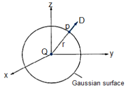
Let us consider a point charge Q located at the origin. To determine D at a point P, we consider a spherical surface as a Gaussian surface, which is symmetrical.
D is normal to this Gaussian surface everywhere so D= Drar, applying Gauss’s Law gives

Where

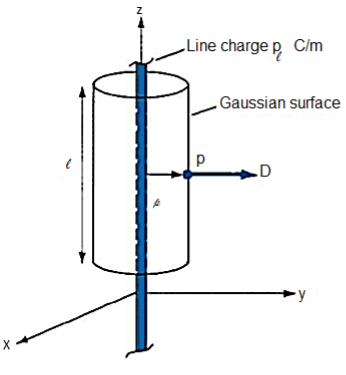
B. INFINITE LINE CHARGE
Let us consider an infinite line of uniform charge  C/m along z axis. We choose a cylindrical surface containing P to satisfy the symmetry condition. The electric flux density D is constant on and normal to the cylindrical Gaussian surface; that is, D=D
 a
a and if we apply Gauss law for a length l, we get

Where  is the surface area of the Gaussian surface. The point worth noting is that
  is zero for the top and bottom surfaces of the cylinder, since D has no z component to those surfaces. That means that D is tangential to those surfaces.
Hence

C. INFINITE SHEET OF CHARGE
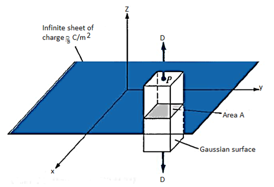
Consider an infinite sheet of uniform charge  s C/m2 lying on the z = 0 plane. To determine D at point P, we choose a rectangular box that is cut symmetrically by the sheet of charge and has two of its faces parallel to the sheet as shown in the figure below. As D is normal to the sheet, D = Dzaz and applying Gauss's law gives

D · dS evaluated on the sides of the box is zero because D has no components along ax and ay. If the top and bottom area of the box, each has area A then:

And thus D = 
Problem: Two point charges Q1 = 10 μC and Q2 = 20 μC are placed at coordinates (1, 1, 0) and (– 1, – 1, 0) respectively. What is the total electric flux passing through a plane z = 20?
Solution: The total flux produced by a charge Q is Q C.
The two charges are on the xy plane as their z co-ordinate is zero. For any charge on the xy plane, by symmetry, half of the flux will be radiated above the xy plane and half of the flux will be radiated below the xy plane.
Since the plane z = 20 is parallel and above to the xy plane, the flux produced by Q1 = 5 μC and Q2 = 10 μC, hence the total flux produced is 15 μC.
ELECTRIC POTENTIAL
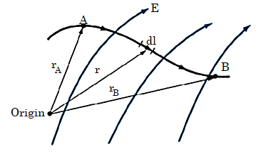
Suppose we wish to move a point charge Q from point A to point B in an electric field E. From Coulomb's law, the force on Q is F = QE so that the work done in displacing the charge by dl is
DW=- F.dl = -QE.dl
The negative sign indicates that the work is being done by an external agent. Thus, the total work done, or the potential energy required, in moving Q from A to B, is
W = -
Dividing W by Q gives Potential Energy per unit charge. This quantity is called as Potential difference between points A and B.
VAB = 
Let us consider an example. Charge Q is located at the origin, The Electric field due to this point charge is:
E = ar
ar
Therefore,
VAB = - 
= 

VAB = VB - VA
Where VB and VA are the potentials (or absolute potentials) at B and A, respectively. Thus, the potential difference VAB may be regarded as the potential at B with reference to A.
When working with point charges, infinity is chosen as a reference; the potential at infinity is assumed to be zero.
Thus, if VA = 0 as rA  in the equation for VAB, the potential at any point (rB
  r) due to a point charge Q located at the origin is
V = 
If the point charge Q is not located at the origin but at a point whose position vector is r', the potential V (x, y, z) or simply V(r) at r becomes
V(r) = 
Problem: A point charge of +1 nC is placed in a space with a permittivity of 8.85 × 10⁻¹² F/m as shown in figure. Find the potential difference VPQ between two points P and Q at distance of 40 mm and 20 mm respectively from the point charge.
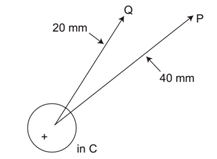
Solution: r1 = 20mm, r2 = 40mm
VPQ = VQ – Vp
=  -
- 
= 
VPQ = -225V
Electric potential of a line of charge
The electric field for an infinite line of charge is dependent on the charge density  and perpendicular distance
  and
and  is a unit vector in the radial direction.
E = 
In a conservative Electric Field, the potential difference between two points and A and B, is given by:
VA - VB = 
Because of symmetry, we choose radial path of integration so 
VA - VB =  =
=  =
=
=  =
= 
If we choose a random point say r0 where VB = 0
VA V =
V = 
Electric potential of a sheet of charge
The electric field associated with a sheet of charge is given by:
E = az
az
V = - = -
= -
1. Gauss's law states that the total electric flux  through any closed surface is equal to the total charge enclosed by that surface.
Thus  = Qenc
That is

=total charge enclosed Q=

By applying the Divergence Theorem to the middle term, we get

If we compare the two volume integrals above:
 =
= 
Which is Maxwell’s First equation of Electrostatics.
2. The potential difference between points A and B is independent of the path taken.
Also, VBA = -VAB that is VBA + VAB =  = 0
= 0
Or

This shows that the line integral of electric field along a closed path must be zero. Physically, this implies that no work is done in moving a charge along a closed path in an electrostatic field. By applying Stoke’s Theorem


This is Maxwell’s Second equation of Electrostatics.
The current through a given area is the electric charge passing through the area per unit time. The SI unit is Amperes (A).
That is, I =
A current of one ampere means that charge is being transferred at a rate of one coulomb per second.
If current  flows through a planar surface
  , then the current density is
J = 
Or 
When current density is not normal to the surface. If the current density is not normal to the surface

Thus, the total current flowing through a surface is

Convection and Conduction Currents
Convection Current does not involve conductors and it does not obey Ohm’s Law. It occurs when current flows through an insulating medium such as liquid, gas or a vacuum.
Here J = 
I is the convection current,  is charge flow density and u is charge velocity and J is the convection current density in amperes per square meter (A/m2).
Conduction Current requires a conductor. When an electric field E is applied, the force on an electron with charge - e is:
F = -eE
If an electron with mass m is moving in an electric field E with an average drift velocity u, according to Newton's law, the average change in momentum of the free electron must match the applied force
 =
= 
Or u = 
Where  is the average time interval between collisions. This indicates that the drift velocity of the electron is directly proportional to the applied field. If there are n electrons per unit volume, the electronic charge density is given by
 = -ne
= -ne
Therefore, the current conduction density is
J =  u =
u =  =
= 
J = 
Where  is the conductivity of the conductor.
Maxwell’s first equation can also be stated in the following way:

The divergence of the electric field in a certain region of space is proportional to the charge density in that region.
It describes how a volume of space enclosing a certain amount of electric charges results in a non-zero electric field proportional to this electric charges.
Another interesting conclusion of the above is that if the closed surface in question does not enclose any electric charge, then the divergence of the electric field affecting the volume must be zero.
That is, the inbound electric lines and outbound electric lines must cancel out exactly. In other words, the electric field is conserved within a region of space not enclosing any electric charge
Maxwell’s second equation:

This implies that the line integral of E along a closed path is zero. Physically, this implies that no network is done in moving a charge along a closed path in an electrostatic field. Thus, an electrostatic field is a conservative field and is referred to as Maxwell's equation (the second Maxwell's equation to be derived) for static electric fields.
For time varying Fields:

A variation of the magnetic field over time induces an electric field in a plane orthogonal to this magnetic field. This is the reformulation of Faraday’s Law of induction.
Electrostatic discharge (ESD) (or static electricity) refers to the sudden transfer (discharge) of static charge between objects at different electrostatic potentials. A good example is the ‘zap’ one feels after walking on a synthetic carpet and then touching a metal doorknob.
Electrostatic discharge (ESD) belongs to a family of electrical problems known as electrical overstress (EOS). Other members of the EOS family include lightning and electromagnetic pulses (EMPs).
ESD poses a serious threat to electronic devices and affects the operation of the systems that contain those devices. An ESD can destroy an integrated circuit (IC), shut down a computer system, cause a fuel tank to explode, and so on.
ESD is a rapid-discharge event that transfers a finite amount of charge between two bodies at different potentials.
What is the cause of ESD? Static charge is a result of an unbalanced electrical charge at rest. It is created when insulator surfaces are rubbed against each other. One surface gains electron, the other surface loses electrons. The excess of electrons on a surface makes it carry negative charge. Similarly, the deficiency of electrons on a surface makes it carry positive charge. When a static charge moves from one surface to the other, it becomes ESD. ESD events occur to balance the charge between two objects. The movement of these charges often occurs rapidly and randomly, leading to high currents.
ESD can occur in one of the following four ways:
• A charged body touches a device such as an IC.
• A charged device touches a grounded surface.
• A charged machine touches a device.
• An electrostatic field induces a voltage across a dielectric that is sufficient to cause breakdown.
An ESD event takes place in the following four stages.
1. Charge Generation-This could be tribo electricity, induction, or conduction.
Triboelectricity requires physical contact between two different materials or the rubbing together of two materials.
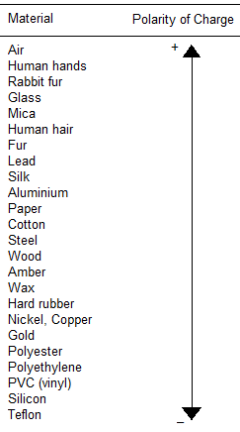
The materials in the above table are charged positively when rubbed by a material below it.
2. Charge transfer: This is the second stage in an ESD event. Charge transfers from the higher potential body to the lower potential body until the potentials between them are equal.
3. Device response: At this stage, we analyze how a circuit responds to a pulse and how it withstands the redistribution of charge. When an ESD event begins, charge starts to redistribute, and this movement of charge generates currents and induces voltages.
4. Device failure: The last stage involves assessing the kind of failure, if any. This is when we determine whether the device survived. There are three kinds of failure: hard failure (i.e., physical destruction), soft failure, and latent failure.
The importance of ESD has led standards organizations to develop guidelines for control and prevention of ESD. The ESD Association has developed a standard known as ANSI/ESD 520.20 (2007) to establish and maintain ESD control. The standard identifies and describes key measurement processes to qualify a company's ESD control program.
Here is a short list of dos and don'ts.
• Treat everything as static sensitive.
• Touch something grounded before handling electronic assemblies or components.
• Wear a grounded wrist strap whenever possible
Cathode Ray Oscilloscope
The cathode-ray oscilloscope (CRO) is a common laboratory instrument that provides accurate time and amplitude measurements of voltage signals over a wide range of frequencies.
The cathode ray is a beam of electrons which are emitted by the heated cathode (negative electrode) and accelerated toward the fluorescent screen. The assembly of the cathode, intensity grid, focus grid, and accelerating anode (positive electrode) is called an electron gun. Its purpose is to generate the electron beam and control its intensity and focus. Between the electron gun and the fluorescent screen are two pair of metal plates - one oriented to provide horizontal deflection of the beam and one pair oriented to give vertical deflection to the beam. These plates are thus referred to as the horizontal and vertical deflection plates. The combination of these two deflections allows the beam to reach any portion of the fluorescent screen. Wherever the electron beam hits the screen, the phosphor is excited and light is emitted from that point. This conversion of electron energy into light allows us to write with points or lines of light on an otherwise darkened screen.
In the most common use of the oscilloscope the signal to be studied is first amplified and then applied to the vertical (deflection) plates to deflect the beam vertically and at the same time a voltage that increases linearly with time is applied to the horizontal (deflection) plates thus causing the beam to be deflected horizontally at a uniform (constant> rate. The signal applied to the vertical plates is thus displayed on the screen as a function of time. The horizontal axis serves as a uniform time scale.
The linear deflection or sweep of the beam horizontally is accomplished by use of a sweep generator that is incorporated in the oscilloscope circuitry.
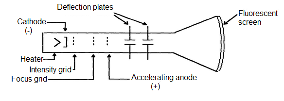
Schematic diagram of Cathode Ray Tube

The deflection of plates
CRO Operation: A simplified block diagram of a typical oscilloscope is shown in the figure below. In general, the instrument is operated in the following manner. The signal to be displayed is amplified by the vertical amplifier and applied to the vertical deflection plates of the CRT. A portion of the signal in the vertical amplifier is applied to the sweep trigger as a triggering signal. The sweep trigger then generates a pulse coincident with a selected point in the cycle of the triggering signal. This pulse turns on the sweep generator, initiating the sawtooth wave form. The sawtooth wave is amplified by the horizontal amplifier and applied to the horizontal deflection plates. Usually, additional provisions signal is made for applying an external triggering signal or utilizing the 60 Hz line for triggering. Also, the sweep generator may be bypassed and an external signal applied directly to the horizontal amplifier.
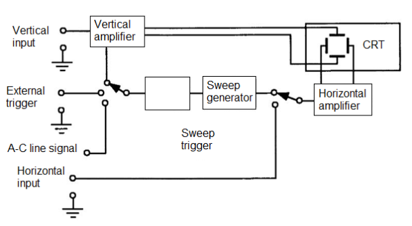
Block Diagram of an oscilloscope
Summary:
1. The two fundamental laws for electrostatic fields (Coulomb and Gauss’s) are presented in this chapter. Coulomb’s law of force states that

2. Based on Coulomb’s law, we define the electric field intensity E as the force per unit charge, that is
 (Point charge only)
3. For a continuous charge distribution, the total charge is given by

 for surface charge
 for volume charge
The E field due to a continuous charge distribution is obtained from the formula for point charge by replacing Q with  and integrating over the line, surface or volume respectively.
4. For an infinite line charge 
And for an infinite sheet of charge.

5. The electric flux density D is related to the electric field intensity (in free space as)

The electric flux through a surface S is 
6.Gauss’s law states that net electric flux penetrating a closed surface is equal to the total charge enclosed that is  . Hence

 (First Maxwell equation to be derived)
When charge distribution is symmetric, so that a Gaussian surface (where D= is constant) can be foumd Gauss’s law is useful in determining
  that is

7. The total work done, or the electric potential energy to move a point charge Q from point A to B in an electric field E is

8. The potential at r due to a point charge Q at r’ is

Where C is evaluated at a given reference potential point; for example, C=0 if  To determine the potential due to continuous charge distribution, we replace Q in the formula for point charge by
  or
or  and integrate over the line, surface or volume respectively.
9. If the charge distribution is not known, but the field intensity E is given we find potential using by

10. The potential difference  , the potential at B with reference to A, is

11. Since an electrostatic field is conservative (the net work done along a closed path in a static E field is zero).

×E=0 (second Maxwell equation to be derived)
12. Given the potential field the corresponding electric field is found by using
E=- V
13. For an electric dipole centered at r’ with dipole moment p, the potential at r is given by

14. The flux density D is tangential to the electric flux lines at every point. An equipotential surface (or line) is one on which V-constant. At every point, the equipotential line is orthogonal to the electric flux line.
15. The electrostatic energy due to n point charges is

For a continuous volume charge distribution

16. Electrostatic discharge (ESD) refers to the sudden transfer of static charge between objects at different electrostatic potentials. Since all semiconductor devices are regarded as ESD sensitive, a good understanding of ESD is required in industry.
The cathode-ray oscilloscope (CRO) is an instrument that provides accurate time and amplitude measurements of voltage signals over a wide range of frequencies. The assembly of the cathode, intensity grid, focus grid, and accelerating anode (positive electrode) is called an electron gun.
References:
1. Kraus and Fleish, “Electromagnetics with Applications”, McGraw Hill International Editions, 5th Edition.
2. Jordan and Balmain, “Electromagnetic Waves and Radiating Systems”, PHI, 1964.
3. Faraday, Maxwell, and the Electromagnetic Field:by Basil Mahon and Nancy Forbes.
4. Electromagnetism: Theory and Applications Book by Ashutosh Pramanik
5. Field and wave electromagnetics Textbook by David K. Cheng