Unit - 2
Magneto statics
It is the force exerted on the charged particle q moving with velocity v through an electric field E and magnetic field B. The entire electromagnetic force F on the charged particle is called Lorentz force which is given by
F = qE + qv x B ---------------------(1)
The first term indicates electric field. The second term indicates magnetic force which has direction perpendicular to both velocity and magnetic field.
The magnetic force is proportional to q and to the magnitude of the vector cross product v × B. In terms of the angle ϕ between v and B, the magnitude of the force equals qvB sin ϕ.
If v is perpendicular to B the particle will follow circular trajectory with radius of r = mv/qB. If the angle ϕ is less than 90°, the particle orbit will be a helix with an axis parallel to the field lines.
If ϕ is zero, there will be no magnetic force on the particle, which will continue to move undeflected along the field lines.
When a conductor is placed with B field perpendicular to current, the magnetic force on both types of charge carriers is in the same direction. This force gives rise to small potential difference between the sides of the conductor.
If a wire with a current i is placed in an external magnetic field B, Since, current represents movement of charges in the wire, the Lorentz force acts on the moving charges. Because these charges are bound to the conductor, the magnetic forces on the moving charges are transferred to the wire.
The force on a small length dl of the wire depends on the orientation of the wire with respect to the field. The magnitude of the force is given by I dlB sin ϕ, where ϕ is the angle between B and dl. There is no force when ϕ = 0 or 180°, both of which correspond to a current along a direction parallel to the field. The force is at a maximum when the current and field are perpendicular to each other. The force is given by dF= idl × B.
The Magnetic Field Intensity or Magnetic Field Strength is a ratio of the MMF needed to create a certain Flux Density (B) within a material per unit length of that material.
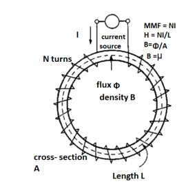
H = At/m, ampere-turns per meter. N is used as the number of turns of wire around a core or magnetic material. So, H = N*I/m.
This is the horizontal axis of the B-H curve for magnetic materials, and is used to vary the magnetic flux within the material by varying the current in the solenoid, thus varying the at (varying the amperes of the ampere-turns).
To determine the B-H curve of a material, the H is varied by controlling the magnitude and polarity of the current flowing in the coil around the sample material, and B is measured.
In free space
In free space, magnetic flux density B is defined as:
 Webers/m2 or Tesla (T).
 (henry/meters)
μ is the permeability of free space.
The total magnetic flux through a surface is given by

Applying the definition of the divergence,

Therefore, the lines H or B are closed lines (E or D are open lines).
Conductor
For the magnetic flux between the conductors of a coaxial line of length d, the magnetic flux density is given by

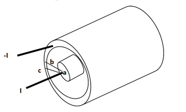
The magnetic flux contained between the conductors in a length d is the flux crossing any radial plane extending from  = a and
  = b and from z=0 and z=d.


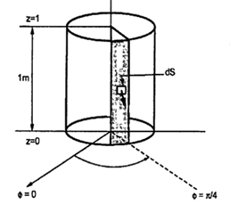
Problem: A radial field  = 2.39 x 10 6 / r cos
  A/m exists in free space. Find the magnetic flux crossing the surface defined by 0 ≤
 ≤ π/4 and 0 ≤ z ≤ 1m.
Solution:
The portion of the cylinder is shown in figure. The flux crossing the given surface is given by

 normal to
  direction is,


Problem: Find the flux passing the portion of the plane  = π / 4 defined by 0.01 < r < 0.05m and 0<z<2 m. A current filament of 2.5 A is along z-axis in the
  direction in free surface.
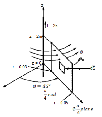
Due to current carrying conductor in free space along z-axis

 A/m
A/m


The flux crossing the surface is given by


 normal to
  direction


Magnetic materials
The magnetic flux density or magnetic induction is the number of lines of force passing through a unit area of material, B. The unit of magnetic induction is the tesla (T).
The magnetizing force which induces the lines of force through a material, is called the field intensity, H (or H-field),
The magnetic induction, B, field intensity, H, and magnetization, M, are related by the equation:
B=μ0(H+M)--------------------(1)
Where μ0 is the permeability of free space and has the value of 4π×10−7 N A−2
Problem:
The amount of flux present in a round magnetic bar was measured at 0.013 webers. If the material has a diameter of 12cm calculate flux density.
The cross sectional aera of the magnetic material in m2 is given as:
Diameter = 12cm
Area =  r 2
r 2
A = 3.142 x 0.06 2= 0.0113 m 2
Flux density =  / A = 0.013 / 0.0113 = 1.15T
Let us consider a conductor carrying direct current I and a steady magnetic field is produced around it. The law helps us to obtain magnetic field intensity  produced at a point P due to differential current element idL. The current carrying conductor is as shown in the figure.
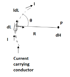
Consider differential length dL and differential current IdL. This is a small part of the current carrying conductor. The point P is at a distance R from differential current element.  is the angle between the differential current element and the line joining point P to the differential current element.
Bio-Savart Law states that the magnetic field intensity  produced at point P due to differential current IdL is,
Proportional to the product of current I and differential length dL.
The sine of angle between the element and the line joining point P to the element.
Inversely proportional to the square of distance R between point P and the element.
Bio-Savart law can be stated as


Where k = constant of proportionality
In SI units, k = 1/ 4 π.

In vector form,
Let dL = Magnitude of vector length  and
and
 = Unit vector in the direction from differential current element to point P.
Then from rule of cross product.

Replacing in equation (3),


Hence 
Equations 4 and 5 is the mathematical form of Bio-Savarts Law.
According to direction of cross product the direction of  is normal to the plane containing two vectors and the normal direction along the progress of right- handed screw turned from
  through smaller angle
  towards the line joining element to point P.
Therefore, direction of  is normal to the plane of paper.
According to right- handed screw rule the direction of  is going into the plane of paper.
The entire conductor is made of differential elements. Therefore, in order to obtain the total magnetic field take the integral

The closed line integral is required to ensure that all the current elements are considered because current can flow only in the closed path provided by close circuit.
If the current element is considered at point 1 and point P at point 2 as shown in the figure, then
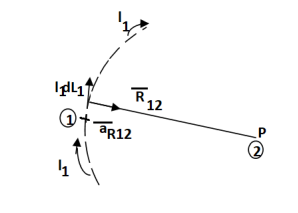

Where
I1 = current flowing through dL1 at point 1.
DL1 = Differential vector length at point 1
a R12 = Unit vector in the direction from element at point 1 to point P at point2.


This integral form is called Biot-Savart law.
Problem:
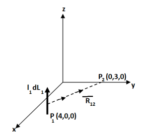
Find the incremental field strength at P2 due to the current element of 2πa2 Am at P1. The co-ordinates of P1 and P2 are (4,0,0) and (0,3,0) respectively.
Solution:
The two points P1 and P2 along with the I1dL1 current element at I1 are shown in figure.
According to Bio-Savart law


While 


Gauss’s Law is useful to obtain  in case of complex problems. I magnetostatics complex problems can be solved using Ampere’s Law.
It states that
The line integral of magnetic field intensity  around closed path is exactly equal to direct current enclosed by that path.
The mathematical representation of Ampere’s circuital law is
 ---------------------(1)
This law is useful to determine  when current distribution is symmetrical.
Proof:
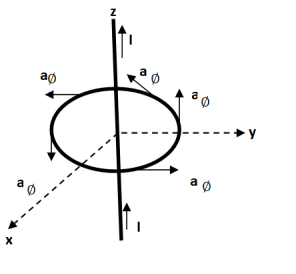
Consider a long straight conductor carrying direct current I placed along z axis as shown in figure. Consider a closed circular path of radius r which encloses the straight conductor carrying direct current I. The point P is at perpendicular distance r from the conductor.
Consider  at point P which is direction
  direction tangential to circular path at point P.
Therefore,

While  obtained at point P, from Biot-Savart law due to infinitely long conductor is,


Since 
Integrating  over the entire closed path,

This proves that the integral  along closed path gives the direct current enclosed by that closed path.
Steps to Apply Amper’s Circuital Law:
Step1: Consider a closed path preferably symmetrical such that it encloses the direct current I once. This is Amperian path.
Step2: Consider differential length  depending upon the co-ordinate system used.
Step3: Identify the symmetry and find in which direction  exists according to co-ordinate system used.
Step 4: Find  . Make sure that
  and
and  are in the same direction.
Step 5: Find the integral of  around the closed path. And equate it to current I enclosed by the path.
To apply Ampere’s circuital law the following conditions must be satisfied,
- The
 i.e., either tangential or normal to the path, at each point of the closed path.
 - The magnitude of
 must be same at all points of the path where
  is tangential.
 due to straight conductors
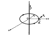
Consider an infinitely long straight conductor which is placed along z-axis carrying direct current I as shown in figure. Consider the Amperian closed path enclosing the conductor as shown in figure. Consider point P on the closed path at which  is obtained. The radius of the path is r from the conductor. The magnitude of
  depends on r and the direction is always tangential to the closed path. So,
  has only component in
  direction say H
  .
.
Consider elementary length  at point P in cylindrical co-ordinates it is r d
 in
in 

According to ampere’s critical law,


Hence  at point P is given by

Circular loop:
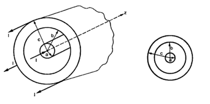
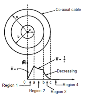
Consider a co-axial cable where the inner conductor is solid with radius a, carrying direct current I. The outer conductor is in the form of concentric cylinder whose inner radius is b and outer radius is c. The cable is placed along z-axis. The current I is uniformly distributed in the inner conductor. When -I is uniformly distributed in the outer conductor.
The space between inner and outer conductor is filled with dielectric say air. The calculation of  is divided corresponding to various regions of the cable.
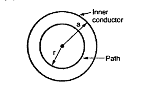
Region 1: Within the inner conductor r<a . Consider a closed path having radius r<a. Hence it encloses only part of the conductor as shown in figure.
The area of cross-section is enclosed in  r2 m2 . The total current flowing is I through area
  a 2 . Hence the current enclosed by the losed path is.

The  again only in
  direction and depends on r.

So, consider  in the
  direction and depends only on r.

According to Ampere’s law,


r<a within conductor
Region 2:
Within a<r<b consider a circular path which encloses the inner conductor carrying direct current I. This is the case of infintely long conductor along z-axis. Hence,  in this region is

Region 3:
Within the outer conductor b<r<c
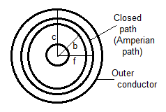
Consider the closed path as shown in figure. The current enclosed is the only part of the curent -I, in the outer conductor. The total current _I is flowing through the cross section  ( c2 – b2) while the closed path encloses the cross section
  ( r2 – b2). Hence, the current enclosed by the closed path of the outer conductor is

 Current in inner conductor enclosed
Total current enclosed by the closed path is,


According toe Ampere’s circuital law,

Now  is again in
  direction only and is a function of r only.
 and
and 


 A/m ….b<r<c
Region 4:
Outside the cable r>c
Consider the closed path with r>c such that it encloses both the conductors that is both currents +I and _I.
The total current enclosed is,
I enc = +I -I = 0A

 … Ampere’s circuital law
 … r>c
… r>c
The magnetic field does not exist outside the cable. The variation of  R is
R is
Infinite sheet of current
Consider an infinite sheet of current in the z=0 plane. The surface current density is  . The current is flowing in positive y direction hence
  Ky
Ky  y. This is shown in figure.
Consider a closed path 1-2-3-4 shown in figure. The width of the path is b while the height is a. It is perpendicular to the direction of current in xz plane.
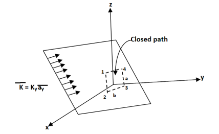
The current flowing across the distance b is given by Kyb

Consider the magnetic lines of force due to current in  direction according to right thumb rule. These are shown in figure.
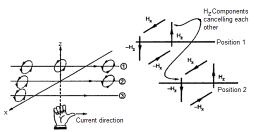
In Figure b it is clear that in between two very closed spaced conductors the components of  in z direction are oppositely directed. All such components cancel each other and hence
  cannot have any component in z direction.
As current is flowing in y direction  cannot have component in y direction.
So  has only component in x direction.
 for z>0
 for z<0
Applying Ampere’s circuit law,


For path 1-2 
For path 3-4 
But  is in x direction while
Hence along the paths 1-2 and 3-4 the integral  .
.
Consider path 2-3 along which 

The path 2-3 is lying in z<0 region for which  is –Hx
  . And the limits from 2 to 3 positive x to negative x hence effective sign of the integral is positive.
Consider the path 4-1 along which  and it is in the region z>0 hence


Equating this to  in equation (6),


Hence,
 for z>0
 for z<0
In general, for an infinite sheet to current density  we can write,

Where  Unit vector normal from the current sheet to the point at which
  is to be obtained.
Problem: The plane y=1 carries current density  . Find H at A (0,0,0) and B (1,5, -2).
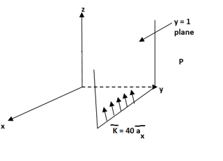
Solution:
The sheet is located at y=1 on which K is in  direction. The sheet is infinite and shown in figure.
The  will be in x direction.
a) Pint A (0,0,0)
 normal to current sheet at point A.


Now 

b) Point B(1,5,-2)
This is to the right of the plare as y=5 for B
 Normal to sheet at point B


Problem: In the region 0<r<0.5m in cylindrical co-ordinates the current density is 
 and J=0 elsewhere. Use Amperes circuital law to find
The current from current density is given by

 normal to
  as
as


Using integration by parts,


For r=0.5, I=7.608[1-0.3678-0.3678] =1.8676A
Consider a closed path with r ≥ 0.5 such that the enclosed current I is 1.876 A. According to Ampere’ circuital law,


 for
for 
A ‘z’ directed current distribution is given by
 . Find
  at any point using Amper’s circuital law.
As current density is given by


Consider a closed path with  which is Amperiab oath,
 while
while 
According to ampere’s circuital law,
 as path has
  . It encloses total I.


Assuming permeability of medium as
 Wb/
Wb/
Problem: An infinitely long straight wire carries 1000 A of current and in the vicinity, there is a circular conducting loop of 100 mm diameter with the centre of the loop 1 m away from the straight conductor. Both the wire and the loop are coplanar. Determine the magnitude and direction of current in the loop that procedures a zero flux density at its centre.
Solution:
The infinitely long wire PQ with  and circular loop with center, O at r=1 m is shown in the figure.
Magnetic flux density  at O due to PQ is given by

Let  be the current through the circular loop such tha
 produced by it at O cancels with
  , giveng zere resultant flux density
 is given


The direction of  is counter-clockwise.
Ampere's circuit law states that the line integral of H around a closed path is the same as the net current Ienc enclosed by the path.
In other words, it can be said that the circulation of H equals Ienc:
 …. (1)
Ampere's law is similar to Gauss's law, since Ampere's law is easily applied to determine H when the current distribution is symmetrical.
Ampere’s law is a special case of Biot-Savart’s Law, it can be derived from Biot-Savart’s Law.
By applying Stokes's theorem to the left-hand side of equation 1, we get:

But

If we compare the two surface integrals, then:
 …….(2)
This is the third Maxwell Equation; it is essentially Ampere's law in differential
Form, whereas eq. 1 is the integral form.
Also, in Eq. 2  ; that is a magnetostatic field is not conservative.
For time varying Magnetic Fields, (2) is written as:

The term  is known as displacement current density.
Magnetic Flux Density
The magnetic flux density B is similar to the electric flux density D. As D =  in free space, the magnetic flux density B is related to the magnetic field intensity H as:
B = ……..(1)
Where  is a constant known as the permeability of free space. The constant is in henrys per meter (H/m) and has the value of

The magnetic Flux through a surface S is given by:
 …….(2)
Where the magnetic flux  ' is in webers (Wb) and the magnetic flux density is in webers per square meter (Wb/m2) or Tesla’s (T).
Unlike electric flux lines, magnetic flux lines always close upon themselves. This is because it is not possible to have isolated magnetic poles (or magnetic charges).
 ……….(3)
This equation is referred to as the law of conservation of magnetic flux or Gauss's law for magnetostatic fields. Although the magnetostatic field is not conservative, magnetic flux is conserved.
By applying Divergence Theorem to equation 3, we obtain:
 ………..(4)
This equation is the fourth Maxwell's equation. It also shows that magnetostatic fields have no sources or sinks. It means that magnetic field lines are always continuous.
Problem:
The following four vector fields are given in Cartesian co-ordinate system. The vector field, which does not satisfy the property of magnetic flux density, is
(a) 

(c) 

Solution
As we know that divergence of magnetic field is zero, therefore B=0
For  the above relation becomes


From the given options, option(c) does not satisfy the above relation.
Hence the correct option is (c)
The Gauss Law of Magnetostatics states that  resulting that isolated magnetic poles or magnetic monopole cannot exist as they appear only in pairs and there is no source or sink for magnetic lines of forces. It is also independent of time i.e. steady state equation.

This is a time dependent equation which represents the modified differential form of Ampere’s circuital law according to which magnetic field is produced due to combined effect of conduction current density and displacement current density.
Maxwell generalized Ampere's law by stating that a magnetic field can be generated as a result of two phenomena:
- Contribution from an electric current flowing through a conductive material (Ampere's law), and
- Contribution resulting from the variation of the electric field.
The insertion of Jd =  was one of the major contributions of Maxwell. Without the term Jd, the propagation of electromagnetic waves (e.g., radio or TV waves) would be impossible.
Lightning is the discharge of static electricity generated in clouds by natural processes.
Lightning may also be regarded as a transient, high-current electric discharge. It is a major natural source of electromagnetic radiation that interferes with modern electronics and communication systems. Lightning strikes somewhere on the surface of the earth about 100 times every second.
Damage caused by lightning is also tremendous. Deaths and injuries to livestock and other animals, thousands of forest and brush fires, damage to buildings, communications systems, power lines, and electrical systems are among the results of lightning.
Lightning can reach from clouds to ground and to other clouds and hence Lightning is classified as of two types: (1) cloud to cloud (2) cloud to ground. Cloud to cloud is a more common discharge. However, Cloud to ground is studied more extensively because of the damage that is inflicted upon properties and livestock. A typical cloud-to-ground lightning carries about 10C to 20 Cat an average height of 5 km above the ground. The portion of the cloud-to-ground discharge that produces physical damage at ground level by virtue of its high current is called the return stroke. The current in a return stroke is typically 10 kA but can be as high as 200 kA.
Under good weather conditions, an electric field of the order 100 V/m exists near the earth's surface. Movements inside a cloud cause the cloud to become an electric dipole, with negative charges in the lower part and positive charges in the upper part. The approach of the negatively charged particles to the ground induces more positive charges, especially on tall, sharp structures. A lightning bolt follows the path of least resistance at the moment of initiation; this is rarely a straight line, and it is unique for each strike.
If we consider that lightning strikes arrive in vertical manner, we can estimate the striking distance as a function of the amplitude of the current of the return stroke. The base striking distance D in meters, and the current I, in kiloamperes, are related as:
D = 10I0.65
Human and animals within the striking distance may be hurt.
A common way to protect people, buildings, and other structures from lightning is to use lightning rods. A lightning rod is a pointed metal rod attached to the roof of a building. It is connected to a copper or aluminum wire, and the wire is connected to a conductive grid buried in the ground nearby. Lightning rods provide a low-resistance path to ground that can be used to conduct the enormous electrical currents when lightning strikes occur. When lightning strikes, the system attempts to carry the harmful electrical current away from the structure and safely to ground.
Magnetic Resonance Imaging (MRI)
MRI is a technique for probing the human body and it came into clinical practice in the 1980’s. It is now a primary diagnostic tool in the field of neurology and orthopaedics. Continued developments in MRI and computer technology have increased its clinical capabilities and its flexible and dynamic.
What is MRI? When placed in a static magnetic field, certain atomic nuclei assume one of two states: one has a higher energy level and the other has a lower energy level. The energy difference between the two states is linearly proportional to the strength of the applied magnetic field. (This is called Zeeman effect.) Thus, the MRI signals received by a probe can be analyzed to study the properties of the nuclei and their environment.
Unlike other imaging techniques, such as X-ray computed tomography, MRI does not require exposure of the subject to ionizing radiation and hence is considered safe. It provides more information than other imaging techniques because MRI signals are sensitive to several tissue parameters.
An MRI machine consists of a magnet and a giant cube 7 feet tall by 7 feet wide by 10 feet long (2 m X 2 m X 3 m), although new models are rapidly shrinking. There is a horizontal tube running through the magnet from front to back. The magnets in use today in MRI machines are in the range of 0.5 T to 2 T. (There is no scientific evidence that fields in that range produce harmful effects in humans.) The patient, lying on his or her back, slides into the tube on a special table. Once the body part to be scanned is in the exact center of the magnetic field, the scan can begin.
MRI has been widely appreciated as a technique that has provided a significant breakthrough in the field of medical diagnosis. Today, an estimated 60 million MRI scans are performed annually to visualize patients' internal structures and diagnose a number of conditions including tumors, stroke damage, heart and brain diseases, and back problems.
Summary:
The Lorentz force equation

Relates the force acting on a particle with charge Q in the presence of EM fields, It expresses the fundamental law relating EM to mechanics
1.The basic laws (Biot-Savart’s and Amperes) that govern magneto static fields are discussed. Biot-Savart’s law, which is similar to Coulomb’s law, states that the magnetic field intensity dH at r due to current

Where  and
and  For surface or volume current distribution, we replace Idl with K dS or Jdv, respectively; that is

2. Ampere’s circuit law which is similar to Gauss’s law, states that the circulation of H around a closed path is equal to the current enclosed by the path; that is,

 (Third Maxwell equation to be derived)
When current distribution is symmetric so hta an Amperian path (on which  is constant) can be found, Ampere’s law is useful in determining H; that is,
 or
or 
3. The magnetic flux through a surface S is given by
 in Wb
in Wb
Where B is the magnetic flux density (in Wb/ ). In free space,

Where 
4. Since an isolated or free magnetic monopole does not exist, the net magnetic flux through a closed surface is zero

 (Fourth Maxwell equation to be derived)
5. At this point, all four Maxwell equations for static EM fields have been derived, namely:


6. The magnetic scalar potential  is defined as
 if J=0
And the magnetic potential A as B=×A
Where A=0 with the definition of A, the magnetic flux through a surface S can be found from

Where L is the closed path defining surface S. Rather than using Biot-Savart’s law, the magnetic field due to a current distribution may be found by using A, a powerful approach that is particularly useful in antenna theory. For a current element I dl at r’, the magnetic vector potential at r is

7. Lightning may be regarded as a transient, high-current electric discharge. A common way to protect people, buildings, and other structures from lightning is to use lightning rods.
References:
1. Kraus and Fleish, “Electromagnetics with Applications”, McGraw Hill International Editions, 5th Edition.
2. Jordan and Balmain, “Electromagnetic Waves and Radiating Systems”, PHI, 1964.
3. Faraday, Maxwell, and the Electromagnetic Field: by Basil Mahon and Nancy Forbes.
4. Electromagnetism: Theory and Applications Book by Ashutosh Pramanik
5. Field and wave electromagnetics Textbook by David K. Cheng