Unit - 3
Boundary Conditions
An electric dipole is formed when two point charges of equal magnitude but opposite sign is separated by a small distance.
Consider the dipole shown in Figure 1:
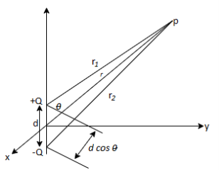
Figure 1: An electric dipole
The potential at point (r, is given by:
 …….(1)
Where r1 and r2 are the distances between P and + Q and P and -Q, respectively. If r >> d, r2 - r1 d cos (
 ), r2r1
 r2, and eq. (1) becomes
 ……….....(2)
Since d cos( ) = d.aR, where d=daZ, if we define
p=Qd
As the dipole moment, then eq.2 can be written as:
 ……..(3)
The dipole moment p is directed from -Q to + Q. If the dipole center is not at the origin but at r', eq.(3) becomes:
 ………………..(4)
The electric field due to the dipole with center at the origin, shown in Figure, can be obtained readily as:
 ……………....(5)

Where p = |p|= Qd
We notice that a point charge is a monopole and its Electric Field varies inversely as r2 and its potential varies inversely as r. We notice that the electric field due to a dipole varies inversely as r3, while its potential varies inversely as r2. The electric fields due to successive higher-order multipoles vary inversely as r4, r5, r6, ..., while their corresponding potentials vary inversely as r3, r4, r5,.. .
To understand polarization, consider an atom of a dielectric. This consists of nucleus with positive and negative charge in the form of revolving electrons in the orbits. The negative charges are in the form of cloud of electrons.
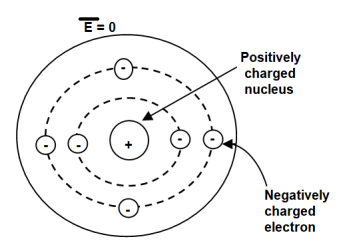
Figure 2. Unpolarized atom of a dielectric
The number of positive charges is same as negative charges and hence atom is electrically neutral. Due to symmetry both positive and negative charges are assumed to be point charges of equal amount coinciding at the centre. This is called unpolarized atom.
When electric field  is applied symmetrical distribution of charges gets disturbed. The positive charges experience a force
  while the negative charges experience a force -
  in opposite direction.
The separation between the nucleus and centre of atom is shown. Such an atom is polarized atom.
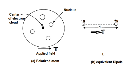
Figure 3. Polarized atom.
Expression:
When dipole is formed due to polarization there exists an electric dipole moment p.
 ----------------------(1)
Where
Q= magnitude of one of the two charges.
 = Distance vector from negative to positive charge.
Let
 Number of dipoles per unit volume
 Total volume of the dielectric
N= Total dipoles=n v
Then the total dipole moment is to be obtained using super position principle as,
 ----------------(2)
If dipoles are randomly oriented  is zero but if dipoles are aligned in the direction of applied E then has significant value.
The polarization  is defined as the total dipole moment per unit volume.

It is measured in coulombs per square meter (C/
------------------------(3)
It can be seen that the units of polarization are same as that of flux density  Thus polarization increases the electric flux density in a dielectric medium. Hence, we can write, flux density in dielectric is,

For isotropic and linear medium, the  and
and  are parallel to each other at every point and related to each other as,

Where  Dimensionless quantity called electric susceptibility of the material.
The susceptibility tells us how sensitive is a given dielectric to the applied electric field 
Substituting (5) in (4)


The quantity  is defined as relative permittivity or dielectric constant of the dielectric material

A conductor has an abundance of charge that is free to move. Let us consider an example, in the figure below. When an external Electric Field Ee is applied, the positive free charges are pushed along the same direction as that of the field and the negative free charges move in the opposite direction. This charge migration takes place very quickly. The free charges first accumulate on the surface of the conductor and form an induced surface charge. Then the induced charges set up an induced internal Electric Field Ei, which cancels the externally applied Electric field Ee. This leads to an important property of a conductor:
A perfect conductor ( ) cannot contain an electrostatic field within it.
A conductor is called an equipotential body which means that potential is same everywhere in the conductor. This is because E = - = 0.
= 0.
Under static conditions,
E=0,  = 0, Vab = 0 inside a conductor.
Where Vab is the potential difference between points a and b in the conductor.
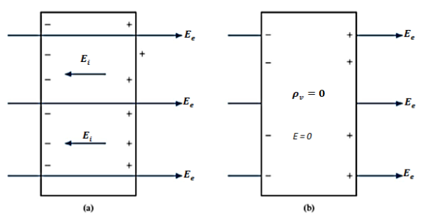
Figure 4: (a) An isolated conductor under the influence of an applied field. (b) A conductor has zero electric field under static conditions.
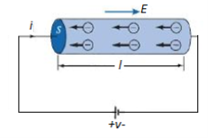
Figure 5: A cylindrical conductor at Potential V
We now consider a conductor whose ends are maintained at a potential difference V, as shown in Figure 5. In this case, E  0 inside the conductor. Since there is no static equilibrium in Figure 5 and the conductor is not isolated but is wired to a source of electromotive force, which compels the free charges to move and prevents the eventual establishment of electrostatic equilibrium. Thus, in this case an electric field must exist inside the conductor to sustain the flow of current.
As the electrons move, they encounter some damping forces called resistance. Based on Ohm's law the resistance of the conducting material is determined.
We assume the conductor has a uniform cross section of area A and is of length l. The direction of the electric field E produced is the same as the direction of the flow of positive charges or current I. This direction is opposite to the direction of the flow of electrons. The electric field applied is uniform and its magnitude is given by:
E =  ….(1)
….(1)
Since the conductor has a uniform cross section,
 ….(2)
….(2)
 ……(3)
……(3)
Hence,  ………(4)
 ……(5)
……(5)
Where  , the resistivity of the conductor. Eq. 5 is used in determining the resistance of the conductor when area of cross-section is uniform.
The main difference between a conductor and a dielectric lies in the availability of free electrons in the outermost atomic shells to conduct current. Although the charges in a dielectric are not able to move about freely, they are bound by finite forces and we may certainly expect a displacement when an external force is applied.
The major effect of the electric field E on a dielectric is the creation of dipole moments that align themselves in the direction of E. This type of dielectric is said to be non-polar. Examples of such dielectrics are hydrogen, oxygen, nitrogen, and the rare gases. Nonpolar dielectric molecules do not possess dipoles until the application of the electric field.
Other types of molecules such as water, sulfur dioxide, hydrochloric acid, and polystyrene have built-in permanent dipoles that are randomly oriented and are said to be polar.
A dielectric material (in which D =  E applies) is linear if
  does not change with the applied E field and non-linear otherwise.
Materials for which  does not vary in the region being considered and is therefore the same at all points (i.e., independent of x, y, z) are said to be homogeneous. They are said to be inhomogeneous (or nonhomogeneous) when
  is dependent on the space coordinates. The atmosphere is a typical example of an inhomogeneous medium; its permittivity varies with altitude.
Materials for which D and E are in the same direction are said to be isotropic. That is, isotropic dielectrics are those that have the same properties in all directions. For anisotropic (or nonisotropic) materials, D, E, and P are not parallel;  or
or  has nine components that are collectively referred to as a tensor. Crystalline materials and magnetized plasma are anisotropic.
When electric field passes from one medium to the other it is necessary to study the conditions at the boundary between two media. The conditions existing at the boundary of two media when field passes from one medium to the other are called boundary conditions.
Depending on the nature of the media there are two situations of boundary conditions:
- Boundary between conductor and free space
- Boundary between two dielectrics with different properties
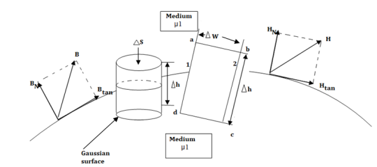
Figure 6: The boundary between conductor and free space.
Consider a boundary between conductor and free space. The conductor has infinite conductivity. For ideal conductor
The field intensity inside the conductor is zero and flux density inside a conductor is zero.
No charge can exist within a conductor. The charge appears on the surface in the form of surface charge density.
The charge density within the conductor is zero.
Thus  and
and  within the conductor is zero.
  is the surface charge density.
In order to determine the boundary conditions, use the closed path and Gaussian surface.
 at the boundary.
Let  be the electric field intensity in the direction making some angle with the boundary. This
  is resolved into two components
The component tangential to the surface
The component normal to the surface.

The integral of  carried over a closed contour is zero that is the work done in carrying unit positive charge along the closed path is zero.
Consider a rectangular closed path abcda as shown in figure. It is traced in clockwise direction hence

Is divided into four parts:

The closed contour is placed in such a way that its two sides a-b and c-d are parallel to tangential direction to the surface while the other two are normal to the surface at the boundary.
The rectangle with height  and width
  is placed in a manner that half of it is conductor and remaining half is free space. Thus
  is in the conductor and
  in free space.
The portion of c-d in conductor where  hence the corresponding integral is zero.

The width  therefore E is constant hence,

But  is tangential to the boundary hence
 where
where 
Ow b-c is parallel to the normal component therefore  along this direction. Let

For small height  EN is assumed constant and taken out of integration.

But out of b-c, b-2 is in free space and 2-c is in the conductor when 


For path d-a the condition is same as for b-c only direction is opposite.

Substituting eq 4 and 8 and 3 and 9 we get


Thus, the tangential component of the electric field intensity is zero at the boundary between conductor and free space.
DN at the boundary
To find the normal component of  select a closed Gaussian surface in the form of right circular cylinder as shown in figure.
  is placed in such a way that
  is in the conductor and
  is in free space. Its axis is normal direction to the surface.
According to Gauss’s law ,

The surface integral must be evaluated over three surfaces top , bottom and lateral.
Let the area of top and bottom be same S

The bottom surface is in conductor where  hence corresponding integral is zero.
The top surface is in free space hence top surface is shifted at the boundary with 

The lateral surface area is 2π r  where r is the radius of the cylinder. But as
  ->0 this area reduces to zero and the integral is zero.
While only component  is normal having magnitude DN the top surface is very small over which DN can be assumed constant and taken out of integration.


From Gauss’s Law

But at the boundary the charge exists in the form of surface charge density  s
s

Equating 16 and 17 we get


Thus the flux leaves the surface normally and the normal component of flux density is equal to surface charge density


Boundary conditions between conductor and dielectric
The free space is dielectric with Thus if the boundary is between conductor and dielectric with


Problem:
A potential field is given as V = 100 e -5x sin 3y cos 4z V. Let point P (0.1, ,
,  ) be located at a conductor free space boundary. At point P find the magnitudes of
a) V b)  c) Et d) EN e)
  f) DN g)
At P , x=0.1 , y=  z =
z =  / 24.
/ 24.
V = 100 e – 0.5 sin 3 / 12 cos 4
 / 24 = 37.1422 V

= -100[-5 e 5x sin 3y cos 4z e -5x (3) (cos3y)(cos 4z)
 + e-5x (sin 3y) (4) (-sin 4z)
At P
 = [-100[-1.857
  = 1.114
  + 85.776
  ]= 185.7
  -111.4
  + 85.776
|E| = 232.9206 V/m
c ) Et = 0 V/m P is on the boundary.
d ) EN = | | = 232.9206 V
e )  = 8.854 x 10 -12 [185.7
  -111.4
  + 85.776
  ]
]
 = 1.992 nC /m2
DN = = 1.992 nC /m2
 = 1.992 nC / m2
From the Gauss’s law in the point form Poisson’s equation can be derived. Consider the Gauss’s law in the point form as

Where  Flux density and
  Volume charge density
It is known that for a homogeneous, isotropic, and linear medium, flux density and electric field intensity are directly proportional. Thus,
 (1)
(1)
 (2)
(2)
 (3)
(3)
From the gradient relationship,
 (4)
(4)
Substituting (4) in (3)
 (5)
(5)
Taking - outside as constant,


Now  operation is called ‘del squared’ operation and denoted as

The above equation is called Poisson’s equation.
If in a certain region volume change density is zero which is true for dielectric medium then the Poisson’s equation takes the form
 (For charge free region)
This is special case of Poisson’s equation is called Laplace’s equation. The  operation is called the Laplacian of V
Applications of Poisson’s and Laplace’s equations
Laplace's equation is of primary importance in solving electrostatic problems involving a set of conductors maintained at different potentials. Examples of such problems include capacitors and vacuum tube diodes. Laplace's and Poisson's equations are not only useful in solving electrostatic field problem; they are used in various other field problems. For example, V would be interpreted as magnetic potential in magnetostatics, as temperature in heat conduction, as stress function in fluid flow, and as pressure head in seepage.
Boundary-value problems are those in which the potentials or their derivatives at the boundaries of a region are specified and we are to determine the potential field within the region. They are solved by using Poisson's equation if 
 or Laplace's equation if
  = 0.
= 0.
Consider two conducting materials M1 and M2 which are placed in a dielectric medium having permittivity  The material M1 carriers a positive charge Q while M2 carries negative charge and the total charge in the system is zero.
In conductors charge cannot reside within the conductor and resides only on the surface. Thus, M1 and M2 charges +Q and -Q reside on the surface of M1 and M2 respectively as shown in figure.
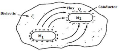
Figure 7: Capacitance
Such a system which has two conducting surfaces carrying equal and opposite charges separated by dielectric called capacitive system giving rise to capacitance.
The electric field normal to the conductor surface and electric flux is directed from M1 towards M2 in such a system. There exists potential difference between surfaces M1 and M2. Let this potential be V12. The ratio of magnitudes of total charge on any one of the two conductors and potential difference between conductors is called capacitance of the two-conductor system.
 (1)
(1)
 (2)
(2)
Q = charge in Coulombs
V = Potential difference in volts.
The capacitance is measured in farads.
As the charge Q resides only on surface of the conductor it can be obtained from Gauss’s law as

While V is work done in moving unit positive charge from negative to positive surface it can be obtained as

Hence,

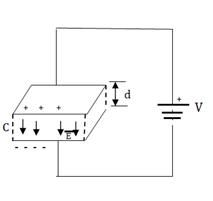
Figure 8: Parallel plate capacitor
Consider a parallel plate capacitor as shown in figure. It is supplied with voltage V.
Let  be the direction normal to the plates
 (1)
(1)
The energy stored is given by

 but
but 
 but
but 
 but
but 


If the dielectric is free space then there is incraese in the stored energy if free space is replaced by other dielectric having 
Energy density is the energy stored per unit volume as volume tends to zero.

 Energy density
 we can write

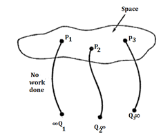
Figure 9
When a unit positive charge is moved from infinity to a point in the field the work is done by the external source and energy is expended. However, if the external source is removed then the unit positive charge will be subjected to force exerted by the field and moved in the direction of force. Thus, to hold the charge at a point in electrostatic field external source has to do work. This energy gets stored in the form of potential energy. When external source is removed, it gets converted to kinetic energy.
Problem: A pair of 200mm long concentric cylindrical conductors of radii 50mm and 100mm is filled with a dielectric with  A voltage is applied between the conductors which establishes
  .
.
Calculate:
a) Capacitance b) voltage -applied c) energy stored.
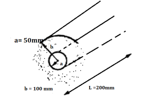
The capacitor is not function of voltage V or  it depends on dielectric and physical dimensions. For coaxial conductors
(a) C = 
= 2 π (10  ) x 200 x 10 -3 / ln [100 x 10 -3 / 50 x 10 -3]
= 160.518 pF
 is function of r hence using,


V = 693.147 kV
c) Energy stored in capacitor =  CV2
CV2
= 55.631 x 10⁻⁶ J
Problem:
A dielectric slab with 500 mm ×500 mm cross-section is0.4 m long. The slab is subjected to a uniform electric field of  . The relative permittivity of the dielectric material is equal to 2. The value of the constant
  is 8.85
  . The energy stored in the dielectric in joules is
(a) 8.85  (b) 8.85
 (c) 88.5 (d) 885
Solution:
Permittivity of free space 
Energy density can be calculated as

Substituting 
And
E


We get


Energy stored = Energy density ×volume
Volume of the dielectric slab=Cross-section ×length

Energy stored=885×0.1 J=88.5 J
Hence the correct option is (c).
Problem:
A capacitor consists of two metal plates each 500 ×500  and spaced 6 mm apart. The space between the metal plates is filled with a glass plate of 4 mm thickness. The relative permittivity of the glass and paper are 8 and 2 respectively. Neglecting the fringing effect the capacitance will be
(Given that 
(a) 983.33pF (b) 1475 pF (c) 6637.5 pF (d) 9956.25 pF
Solution:
Capacitance C of a parallel plate is 
Area of metal plates 
Thickness of the glass dielectric plated 


For the paper dielectric layer, thickness 


Since the Interface is parallel to the conducting plate, the overall capacitance C is given by series combination 


Problem: The capacitance of an isolated sphere of radius10 cm in air is equal to?
We know that
Radius of sphere, a = 10 cm.
Permittivity ε (for air) = ε0
Capacitance of isolated spherical shell of radius a
Can be calculated using relation:


Each orbit consists of electrons which orbit the central positive nucleus. The electrons also rotate about their own axes. Thus, an internal magnetic field is produced by electrons orbiting around the nucleus as in Figure 10 (a) or electrons spinning as in Figure 10 (b). Both these electronic motions produce internal magnetic fields Bi that are similar to the magnetic field produced by a current loop of Figure 11. The equivalent current loop has a magnetic moment of m = IbSan, where S is the area of the loop and Ib is the bound current (bound to the atom).
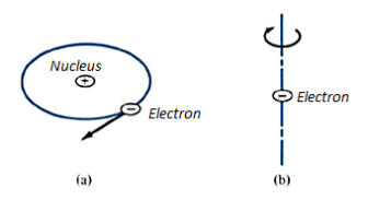
Figure 10: (a) Electron orbiting around the nucleus (b) Electron Spin
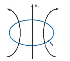
Figure 11: Circular current loop equivalent to electronic motion of electron
Without an external B field applied to the material, the sum of m, s is zero due to random orientation as in Figure 12(a). When an external B field is applied, the magnetic moments of the electrons more or less align themselves with B so that the net magnetic moment is not zero, as illustrated in Figure 12(b).
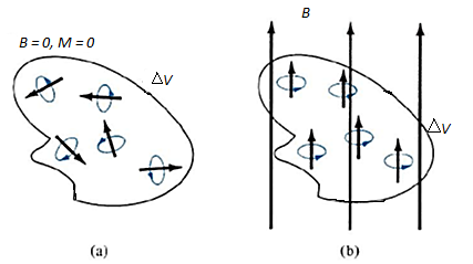
Figure 12: Magnetic dipole moment in a volume  : (a) before B is applied (b) after B is applied.
The magnetic flux density or magnetic induction is the number of lines of force passing through a unit area of material, B. The unit of magnetic induction is the tesla (T).
The magnetizing force which induces the lines of force through a material, is called the field intensity-H (or H-field). The magnetic induction- B, field intensity-H, and magnetization- M, are related by the equation:
B=μ0(H+M)--------------------(1)
Where μ0 is the permeability of free space and has the value of 4π×10−7 N A−2
Classification of materials:
In general, we may use the magnetic susceptibility  or the relative permeability
  to classify materials in terms of their magnetic property or behavior. A material is said to be nonmagnetic if
  (
( ); it is magnetic otherwise. Free space, air, and materials with
  (
( ) are regarded as nonmagnetic.
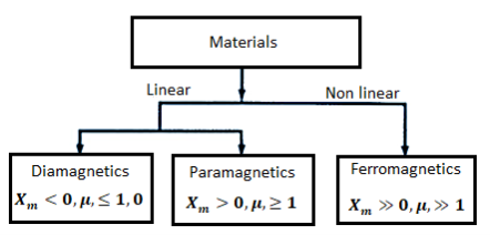
Materials may be grouped into three major classes: diamagnetic, paramagnetic, and ferromagnetic. This rough classification is depicted below. A material is said to be diamagnetic if it has μr  (i.e., very small negative
  ). It is paramagnetic if
  r
r 1 (i.e., very small positive
  ). If μr >> 1 (i.e., very large positive
  ), the material is ferromagnetic.
Diamagnetism occurs when the magnetic fields in a material that are due to electronic motions of orbiting and spinning completely cancel each other. Thus, the permanent (or intrinsic) magnetic moment of each atom is zero and such materials are weakly affected by a magnetic field. For most diamagnetic materials (e.g., bismuth, lead, copper, silicon, diamond, sodium chloride), is the order of -10-5
Materials whose atoms have nonzero permanent magnetic moment may be paramagnetic or ferromagnetic. Paramagnetism occurs when the magnetic fields produced in a material by orbital and spinning electrons do not cancel completely. Unlike diamagnetism, paramagnetism is temperature dependent. For most paramagnetic materials (e.g., air, platinum, tungsten, potassium),  is the order of +10-5 to +10-3 and is temperature dependent.
Ferromagnetism occurs in materials whose atoms have relatively large permanent magnetic moment. They are called ferromagnetic materials because the best-known member is iron. Other members are cobalt, nickel, and their alloys.
Ferromagnetic materials have the following properties:
1. They are capable of being magnetized very strongly by a magnetic field.
2. They retain a considerable amount of their magnetization when removed from the field.
3. They lose their ferromagnetic properties and become linear paramagnetic materials when the temperature is raised above a certain temperature known as the curie temperature. Thus, if a permanent magnet is heated above its curie temperature (770°C for iron), it loses its magnetization completely.
4. They are nonlinear; that is, the constitutive relation B = JL0JLI does not hold for
Ferromagnetic materials because JLr depends on B and cannot be represented by a single value.
Problem: The amount of flux present in a round magnetic bar was measured at 0.013 webers. If the material has a diameter of 12cm calculate flux density.
The cross sectional aera of the magnetic material in m2 is given as:
Diameter = 12cm
Area =  r 2
r 2
A = 3.142 x 0.06 2= 0.0113 m 2
Flux density =  / A = 0.013 / 0.0113 = 1.15T
To derive normal and tangential boundary conditions for magnetostatics:
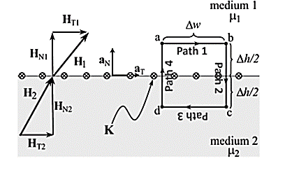
According to Ampere’s circuit law:
 dL = I enc
The current enclosed by the path is

Break H into four Integrals
 =Kw
=Kw
Path 1: =
=  T1 a T dL a T = H T1
Path 2:  N1 aN dL aN +
  N2 aN dL aN = -(HN1 + HN2)
Path 3:  dL =
dL =  T2aT dLaT= -HT2
Path 4:  dL =
dL =  N2dL aN+
  N1 a NdL aN = (H N1 + H N2)
Combing the results, we get
 dL = Ienc

Tangential BC = HT1 – HT2 = K
A more general expression for the first magnetostatic boundary condition can be written as

Where a21 is a unit vector normal going from media 2 to media 1.
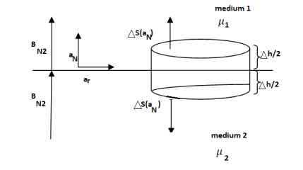
Gauss’s Law for Magnetostatic fields:
 ds = 0
To find the second boundary condition, we center a Gaussian pillbox across the interface as shown in Figure.
We can shrink h such that the flux out of the side of the pillbox is negligible.
Then we have

For normal BC

Thus, we see that the normal component of the magnetic flux density must be continuous across the boundary.
B N1 = B N2

We can say that
H N1 ≠ H N2
Problem:
The magnetic field intensity is given as H1 = 6ax + 2ay + 3az (A/m) in a medium with mr1 = 6000 that exists for z < 0. We want to find H2 in a medium with mr2 = 3000 for z >0.
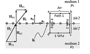
Step (a) and (b): The first step is to break H1 into its normal component (a) and its tangential component (b).
Step (c): With no current at the interface, the tangential component is the same on both sides of the boundary.
Step (d): Next, we find BN1 by multiplying HN1 by the permeability in medium 1.
Step (e): This normal component B is the same on both sides of the boundary.
Step (f): Then we can find HN2 by dividing BN2 by the permeability of medium 2.
Step (g): The last step is to sum the fields.
According to Coulombs lw the force Fe exerted on an electric charge can be obtained. The force related to electric field  as
as

For positive charge the force on it is in the direction of  . This force is referred as electric force.
Now consider that a charge is placed in a steady magnetic field. It experiences force only if it is moving. Then a magnetic force exerted on charge Q moving with a velocity  in a steady magnetic field is given by

The magnitude of the magnetic force  is directly proportional to the magnitudes of Q, v and B and also sine of angle between
  and
and  . The direction of Fm is perpendicular to the plane containing
  and
and  both as shown in figure.
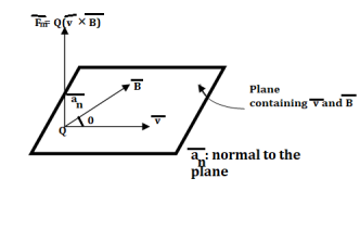
The magnetic force Fm is dependent on the velocity of the moving charge. But Fm cannot work on moving charge as it is at right angle to the direction of motion of charge.
Problem:
In a cylindrical co-ordinate  Wb/m is a vector magnetic potential in a certain region of free space. Find
  and using
  find the thecurrent I crossing the surface 0≤ r≤1, 0≤
 ≤ 2
≤ 2 and z=0.
Vector magnetic potential Wb/m.
Wb/m.
Now 

Now 


Now 


Now  where
where 


Problem: Find out the magnetic vector potential in the vicinity of a very long straight wire carrying a current I. Hence find magnetic field density and magnetic field strength.
Solution:
Consider an infinitely long filament carrying direct current I placed along z-axis as shown in figure.
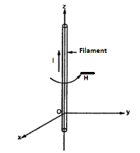
The magnetic field intensity due to such filament is given by,
H = 1/ 2  a
a
If it is placed in free space 

Assuming cylindrical co-ordinate system,


Problem:
The magnetic vector potential in a region is defined by  An infinitely long conductor, having a cross-section area, a=55
 and carrying a DC current
  in the y-direction, passes through this region as shown in the figure. Determine the expression for(a)
  (b) force density f exerted on the conductor.
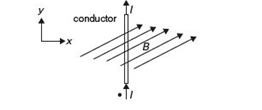
Solution
Figure given below shows infinitely long conductor placed in the y-direction and the magnetic field due the current carrying conductor
Given vector magnetic potential  where
where 
We know that magnetic flux density, can be calculated using


In the above relation 

We can calculate the differential force on the conductor using the relation given below


Force on a unit length of the conducto6r and having cross-section area a=5  will be equal


Problem: An electron moves in the XY-plane with a speed of 106 m/s. Its velocity vector makes an angle of 60° with X-axis. A magnetic field of magnitude 10-2 T exists along the Y-axis. Compute the magnetic force exerted on the electron and its direction.
Solution: Speed of electron in XY-plane is given as v = 106 m/s along OP as shown figure given below.

Magnetic field 
Magnetic force on the electron can be calculated as


Arrange a loop of wire so that the magnetic field pushes one way on one side and the other way the opposite side.
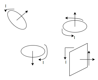
The current through a coil of wire immersed in a magnetic field causes magnetic force to spin the coil. Every loop of current and direction associated with it is perpendicular to the plane of the loop in the direction that right thumb would point if right fingers curled around the coil.
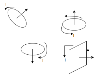
The magnetic force on a current carrying loop tries to align the loops normal vector with the magnetic field.
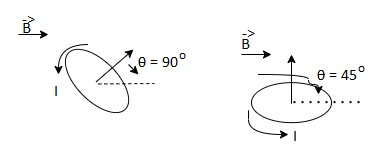
Suppose a magnetic field runs left to right then
The result of a push one way on one side of the coil and a push the other way on the other side is a torque an entity that causes the coil to spin.
The larger the torque the more resistance to spinning can be overcome. The torque on a coil of current carrying wire

Where
N= no of loops of wire in the coil.
I = current through coil
A = area of coil.
B = magnetic field strength (Tesla)
 angle between magnetic field and normal to coil.
Magnetic Levitation
Magnetic levitation (maglev) is a way of using electromagnetic fields to levitate things without any noise or the need for liquid fuel or air. Maglev is the means of floating one magnet over another. Magnetic levitation employs diamagnetism, an intrinsic property of many materials referring to their ability to expel temporarily a portion of an external magnetic field. As a result, diamagnetic materials repel and are repelled by strong magnetic fields.
Superconductors are ideal diamagnetic and completely expel magnetic fields at low temperatures. It is possible to levitate superconductors and other diamagnetic materials. This property is also used in maglev trains. A superconductor is perfectly diamagnetic, which means that it expels a magnetic field. Other diamagnetic materials are commonplace and can also be levitated in a magnetic field if it is strong enough.
There are two types of maglev: electromagnetic levitation (EML), which uses the attractive force between electromagnets on the levitated object and the circuit on the ground, and electrodynamic levitation (EDL), which makes use of the repulsive force between magnets (superconductive magnets) on the levitated object and induced current in the secondary circuit on the ground.
Any type of maglev system consists of three subsystems: a magnetic suspension, a propulsion motor, and a power system. The magnetic suspension is supposed to ensure a stable suspension of a vehicle in its own magnetic field. The propulsion motor should produce a propulsion force sufficient for a continuous flight of the vehicle along an assigned track with a given speed. The power system provides uninterrupted power supply.
If the repulsive force due to a magnetic field on a diamagnetic object is exactly equal to the weight of the object, then the object may be levitated in air. The magnetic fields required for this type of levitation are very large, typically 17 T. To produce such large fields requires using superconductive magnets. Thus, maglev relies on superconductors in practical applications.
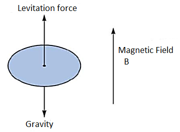
Figure 13: A levitated object
RF MEMS
MEMS stands for micro electro mechanical systems. These devices and systems range in size from a few micrometers to a few millimeters. The field of MEMS (or nanotechnology) encompasses all aspects of science and technology and is involved with things on a smaller scale. MEMS technology gives scientists and engineers the tools to build things that have been impossible or prohibitively expensive with other technologies.
MEMS technology has emerged with a major application area in telecommunications, particularly in optical switching and wireless communication.
Radiofrequency MEMS technologies are helping fuel this expansion. The integration of MEMS into traditional RF circuits has resulted in systems with superior performance levels and lower manufacturing costs. RF MEMS are providing critical reductions in power consumption and signal loss to extend battery life and reduce weight. RF MEMS devices have a broad range of potential applications in military and commercial wireless communication, and in navigation and sensor systems. Though RF MEMS devices are small, they can be very complex, commonly encompassing multiple interdependent engineering disciplines.
RF MEMS application areas are in phased arrays and reconfigurable apertures for defense and communication systems, and in switching networks for satellite communications. As a breakthrough technology, allowing unparalleled synergy between apparently unrelated fields of endeavor such as biology and microelectronics, many new MEMS applications will emerge, expanding beyond that which is currently identified or known.
Electromagnetic Pump
An electromagnetic pump is a pump that moves liquid metal, molten salt, brine, or other electrically conductive liquid using electromagnetism. A magnetic field is set at right angles to the direction the liquid moves in, and a current is passed through it. This causes an electromagnetic force that moves the liquid.
Applications include pumping liquid metal through a cooling system. Many wave-soldering machines used electromagnetic pumps to circulate molten solder.
The principal classifications of electromagnetic pumps can be made in function of operation principle and shape. Depending on the way of generation the current density J in the pumping channel, electromagnetic pumps are of a) conduction type (also known as Faraday pumps), and b) induction pumps. In general, both types include field coils for electromagnetic field generation.
Conduction pumps are built with rectangular channels due to the facility with which the directions of magnetic flux density and current density vectors can be correlated with the channel geometry thus the pumping force to result in the desired direction. The electrodes are in electrical contact with the electro conductive fluid and connected to a voltage supply of DC or AC type. The magnitude of the current flowing between the two electrodes depends on the voltage supply and fluid electrical conductivity.
Another electromagnetic pump classification criterion is by the channel cross-section shape. Besides rectangular channels, there are cylindrical and annular channels. Cylindrical and annular pumps are of induction type, therefore with AC supply and the particularity is that the field coils are the source for both current density and magnetic field.
Working Principle:
A magnetic field (brc) always exists around the current (I) carrying conductor. When this current carrying conductor is subjected to an external magnetic field (Bap), the conductor experiences a force perpendicular to the direction of I and Bap. This is because the magnetic field produced by the conductor and the applied magnetic field attempt to align with each other. A similar effect can be seen between two ordinary magnets.
This principle is used in an electromagnetic pump. The current is fed through a conducting liquid. Two permanent magnets are arranged to produce a magnetic field Bap as shown in the figure. The supplied current has a current density (J) and the magnetic field associated with this current can be called as 'Reaction magnetic Field (brc)'. The two magnetic fields Bap and brc attempt to align with each other. This causes mechanical motion of the fluid.
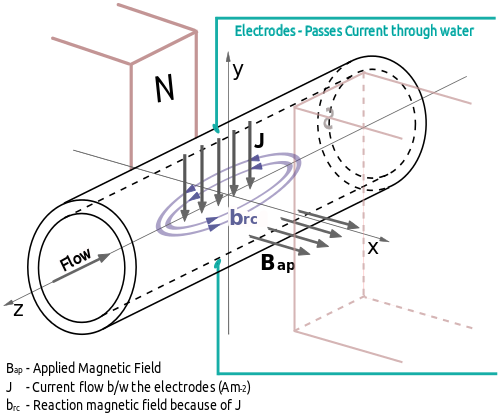
Schematic of Electromagnetic Pump
Summary:
Electric Potential of a dipole:

Electric Field due to a dipole:

The macroscopic effect of polarization on a given volume of a dielectric material is to “paint” its surface with a bound charge  and leave within it an accumulation of bound charge
  where
where  and
and  .
.
In a dielectric medium, the D and E fields are related as D=E, where = , is the permittivity of the medium while E and P are related as
The electric susceptibility  of a dielectric measures the sensitivity of the material to an electric field.
A dielectric material is linear if D=E holds, that is if, is independent of E. It is homogeneous if is independent of position. It is isotropic if is a scalar.
For a dielectric-conductor interface,

Because E=0 inside the conductor.
Boundary condition must be satisfied by an electric field existing in two different media separated by an interface. For a dielectric interface


In a nonhomogeneous region, Poisson’s equation is

For a homogeneous region, is independent of space variables. Poisson’s equation becomes

In a charge-free region ( ). Poisson equation becomes Laplace’s equation; that is

Capacitance can be defined as:

Energy density: 
The torque on a coil of current carrying wire:

Based on the Lorentz force law, the force experienced by a current I dI in a magnetic field B is

From this, the magnetic field B is defined as the force per unit current element.
The torque on a current loop with magnetic moment m in a uniform magnetic field B is

A magnetic dipole is a bar magnet or a small filamental current loop it is so called because its B field lines are similar to the E field lines of an electric dipole.
When a material is subjected to a magnetic field, it becomes magnetized. The magnetization M is the magnetic dipole moment per unit volume of the material. For linear material,

Where  is the magnetic susceptibility of the material.
In terms of their magnetic properties, materials are either linear (diamagnetic or paramagnetic or nonlinear (ferromagnetic). For linear materials
Where =permeability and  relative permeability of the material. For nonlinear material B=(H) H, that is does not have a fixed value; the relationship between B and H is usually represented by a magnetization curve.
The boundary conditions that H or B must satisfy at the interface between two different media are

 or
or  if K=0
Where  is a unit vector directed from medium 1 to medium 2.
Magnetic levitation (maglev) is a way of using EM fields to levitate objects. One important area of applications of maglev is transportation. Conventional railroads operate at speeds below 300 km/hr. While maglev vehicles are designed for operating speeds of up to 500 km/hr.
An electromagnetic pump is a pump that moves liquid metal, molten salt, brine, or other electrically conductive liquid using electromagnetism.
MEMS also known as micro electro mechanical systems are majorly used in optical switching and communication systems.
References:
1. Kraus and Fleish, “Electromagnetics with Applications”, McGraw Hill International Editions, 5th Edition.
2. Jordan and Balmain, “Electromagnetic Waves and Radiating Systems”, PHI, 1964.
3. Faraday, Maxwell, and the Electromagnetic Field:by Basil Mahon and Nancy Forbes.
4. Electromagnetism: Theory and Applications Book by Ashutosh Pramanik
5. Field and wave electromagnetics Textbook by David K. Cheng