Unit - 4
Time Varying Electromagnetic Fields: Maxwell Equations
In Electrostatics the Electric potential V is related to Electric field intensity E (E = - ). Similarly, we can define a potential associated with magnetostatic field B. This Magnetic Potential could be either scalar VM or vector A.
To define Vm or A, two important identities must be known:
 …..(1)
 ….(2)
….(2)
Just as E = - V, we define the magnetic scalar potential Vm (in amperes) as related to H according to
H = - , if J = 0 ….(3)
Also we know that J =  =
=  .
.
The Scalar Magnetic Potential is only defined in the region where J = 0.
In a magnetostatic field  , to satisfy eq.(2) we define vector magnetic potential A (Wb/m) such that
B =  ….(4)
….(4)
Just as we defined
V = 
 for line current
 for surface current
 for volume current
Poisson's and Laplace's equations are easily derived from Gauss's law (for a linear, isotropic material medium):
 …(1)
…(1)
And  …..(2)
Substituting (2) in (1)  = 0…..(3)
For an inhomogeneous medium. For a homogeneous medium eq.3 becomes
 …………………..(4)
This is known as Poisson's equation. A special case of this equation occurs when  then equation 4 becomes:
 ……(5)
……(5)
This is Laplace’s Equation
For an inhomogeneous medium  is not constant and for a homogeneous medium
  is constant.
Laplace's equation is of primary importance in solving electrostatic problems involving a set of conductors maintained at different potentials.
Laplace's and Poisson's equations are not only useful in solving electrostatic field problem; they are used in various other field problems. For example, V would be interpreted as magnetic potential in magnetostatics, as temperature in heat conduction, as stress function in fluid flow, and as pressure head in seepage.
According to Faraday’s experiment a static magnetic field cannot produce any current flow but with time varying field an electromotive force is induced which may drive current in a closed path or circuit.
This emf is nothing but a voltage that induces from changing magnetic fields of motion of conductors in magnetic field.
Statement
The electromagnetic force induces in a closed path or circuit is proportional to the rate of change of magnetic flux enclosed by closed path.
Faraday’s law can be stated as:
 volts
volts
Where N is the no of turns in the circuit.
e is the induced emf.
The minus sign indicates that the direction of the induced emf is such that it produces a current which will produce a magnetic field opposite to the original field.
Problem:
A conductor 1cm in length is parallel to z-axis and rotates at radius 25m at 1200 rpm. Find the induced voltage if the radial field is given by  = 0.5
= 0.5  .
.


To find 
In one minute no of revolution = 1200 rpm
1 sec = 1200/60 = 20 revolution
Distance travelled in one revolution = 2π r
Distance travelled in 20 revolution = 2π r x 20 = 40 π r.


Consider the connection between emf and electric field, we examine how Faraday's law links electric and magnetic fields. For a circuit with a single turn (N = 1) the eq. Becomes

 ------------ eq. (i)
In a time-varying situation, both electric and magnetic fields are present and are interrelated. The variation of flux with time as in equation may be caused in three ways:
1. By having a stationary loop in a time-varying B field
2. By having a time-varying loop area in a static B field
3. By having a time-varying loop area in a time-varying B field.
Translational EMF
This is depicted in figure 1 where the stationary conducting loop is in a time varying magnetic field B. Therefore,


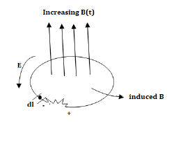
This emf is induced by the time-varying current in a stationary loop referred as transformer emf in power analysis due to transformer action. By applying Stokes's theorem to the middle term in eq. (ii), we obtain

For the two integrals to be equal, their integrands must be equal; that is,

This is one of the Maxwell's equations for time-varying fields. It shows that the time varying E field is not conservative. The work done in taking a charge about a closed path in a time-varying electric field, for example, is due to the energy from the time-varying magnetic field.
Motional EMF
Consider a simple circuit in which a conducting rod of length l slides along a U-shaped conducting frame in the presence of a uniform magnetic field. This circuit is illustrated in Figure.
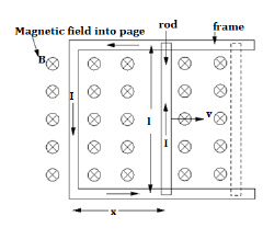
Suppose that the magnetic field is directly perpendicular to the plane of the circuit. Suppose we move the rod to the right with the constant velocity v.The magnetic flux linked by the circuit is simply the product of the perpendicular magnetic field-strength, B, and the area of the circuit, lx, where x determines the position of the sliding rod. Thus,

Now, the rod moves a distance  in a time interval
  , so in the same time interval the magnetic flux linking the circuit increases by

It follows, from Faraday's law, that the magnitude of the emf  generated around the circuit is given by

Thus, the emf generated in the circuit by the moving rod is simply the product of the magnetic field-strength, the length of the rod, and the velocity of the rod. If the magnetic field is not perpendicular to the circuit, but instead subtends an angle  with respect to the normal direction to the plane of the circuit, then it is easily demonstrated that the motional emf generated in the circuit by the moving rod is

Where  is the component of the magnetic field which is perpendicular to the plane of the circuit.
We will reconsider Maxwell's curl equation for magnetic fields (Ampere's circuit law) for time varying conditions.
For static EM fields, we recall that
 ….(1)
….(1)
But the divergence of the curl of any vector field is ZERO.
 …..(2)
The continuity of current requires that

 …....(3)
Since eq. (2) and (3) are incompatible for time varying conditions, eq.(1) is modified to agree with (3). A term is added in (1) to get
 ……..(4)
Where Jd is to be determined and defined. Again, the divergence of the curl of any vector is zero. Hence:
 ……….(5)
In order for (5) to agree with (3)
 =
=  =
=  =
= 
Or  =
=  ……..(6)
Substituting (6) into (4), we get:

This is Maxwell's equation (based on Ampere's circuit law) for a time-varying field. The term Jd = is known as displacement current density and J is the conduction current density (J =
  E).
E).
Problem:
Consider the following statements with reference to the equation 
1. This is a point from of the continuity equation.
2. Divergence of current density is equal to the decrease of charge per unit volume per unit at every point.
3. This is Maxwell’s divergence equation.
4. This represents the conservation of charge.
Select the correct answer
(a) Only 2 and 4 are true
(b) 1, 2 and 3 are true
(c) 2,3 and 4 are true
(d) 1,2 and 4 are true.
Solution:
If  is surface charge density in C/
 and is the volume charge density in C
 then according to point form of continuity equation we have.

Therefore option (1) is true.
According to Integral form of the Maxwell’s equation, we have

From the above equation we conclude that current through closed surface or outward flow of positive charge is balanced by the closed surface or in other words this equation are represents the charges can be either created nor destroyed.
Therefore option (4) is also true.
 represents diveregence of current density
  represents the decrease of charge unit volume per unit time at every point.
Therefore option (2) is also true.
Hence, Statements (1), (2) and (4) are true.
From the principle of charge conservation, the time rate of decrease of charge within a given volume must be equal to the net outward current flow through the surface of the volume. Thus current Iout coming out of the closed surface is
Iout = 

 …….(1)
Where Qin is the total charge enclosed by the closed surface. Applying divergence theorem:
 ……..(2)
But
 ………(3)
Substituting 2 and 3 in 1:

 ……..(4)
Which is called the continuity of current equation or just continuity equation. The continuity equation is derived from the principle of conservation of charge and essentially states that there can be no accumulation of charge at any point. For steady currents,  , and hence
  · J = 0, showing that the total charge leaving a volume is the same as the total charge entering it. Kirchhoff's current law follows from this.
For time varying case, the relationship among the field vectors written as
 -------1
 ----2
----2
 -----3
 --------4
In addition, from the principle of conservation of charges we get the equation of continuity

The equation must be consistent with equation of continuity We observe that
 -----5
Since  is zero for any vector
Thus  applies only for the static case i.e., for the scenario when
Suppose we are in the process of charging up a capacitor as shown in figure
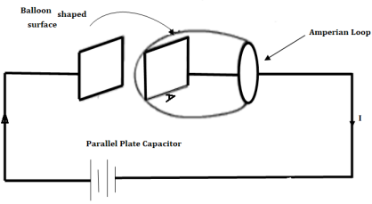
Let us apply the Ampere's Law for the Amperian loop shown in figure. Ienc = I is the total current passing through the loop. But if we draw a balloon shaped surface as in figure, no current passes through this surface and hence Ienc = 0.
But for non-steady currents such as this one, the concept of current enclosed by a loop is ill-defined since it depends on what surface you use.

= (1)
(1)
= (2)
(2)
 (3)
(3)
The equation (3) is valid for static as well as for time varying case.Equation (3) indicates that a time varying electric field will give rise to a magnetic field even in the absence of The term  has a dimension of current densities (A/m2) and is called the displacement current density.
The modified set of equations
 (4)
(4)
 (5)
(5)
 (6)
(6)
 (7)
(7)
Is known as the Maxwell's equation and this set of equations apply in the time varying scenario, static fields in this case is 
- Integral form:


The modification of Ampere's law by Maxwell has led to the development of a unified electromagnetic field theory. By introducing the displacement current term, Maxwell could predict the propagation of EM waves.
Poynting theorem states that the net power flowing out of a given volume V is equal to the time rate of decrease of stored electromagnetic energy in that volume decreased by the conduction losses is the total power leaving the volume = rate of decrease of stored electromagnetic energy ohmic power dissipated due to motion of charge.
Proof:
The energy density carried by the electromagnetic wave can be calculated using Maxwell's equations


 (5)
(5)
 (6)
(6)
 (7)
(7)


=

So from equation (vii) 
 (viii)
Integrating equation (viii) over a volume V enclosed by a surface S

Or 
As 
Or 
Or 
Or 
That is the Total power leaving the volume = rate of decrease of stored e.m.f energy - ohmic power dissipated due to charge motion
This equation (ix) represents the poynting theorem according to which the net power flowing out of a given volume is equal to the rate of decrease of stored electromagnetic energy in that volume minus the conduction losses.
In steady-state, Maxwell's equations reduce to


The solutions to these equations are easily found using the Green's function for Poisson's equation


The time-dependent Maxwell equations reduce to


We can solve these equations using the time-dependent Green's function. We find that

With a similar equation for A. Using the well-known property of delta-functions, these equations reduce to


However, when we calculate the contribution of charges and currents at position  to these integrals we do not use the values at time
  , instead we use the values at some earlier time. It is simply the latest time at which a light signal emitted from position
  would be received at position
  before time
  . This is called the retarded time. Likewise, the potentials are called retarded potentials. It is often useful to adopt the following notation

The square brackets denote retardation (i.e., using the retarded time instead of the real time). Therefore, we get


The time dependence in the above equations is taken as read.
We are now able to understand electromagnetism at its most fundamental level. A charge distribution (r,t) can thought of as built up out of a collection, or series, of charges which instantaneously come into existence, at some point  and some time
  , and then disappear again. Mathematically, this is written

Likewise, we can think of a current distribution j(r,t) as built up out of a collection or series of currents which instantaneously appear and then disappear:

Each of these ephemeral charges and currents excites a spherical wave in the appropriate potential. Thus, the charge density at  and
and  sends out a wave in the scalar potential:

Likewise, the current density at  and
and  sends out a wave in the vector potential:

Memristors
In 1971 Leon 0. Chua of the University of California-Berkeley, introduced the memristor Figure 9 as one of the four basic circuit elements, coequal in importance with the other well-known circuit elements, namely, resistor (R), inductor (L), and capacitor (C).
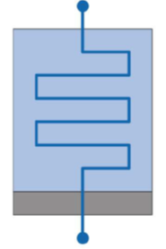
Figure: Schematic of Memristor
Chua characterized the memristor in terms of the electric charge and the magnetic flux. He also linked this relationship with the quasi-static expansion of Maxwell's equations.
A charge-controlled memristor can be defined as a two-terminal element satisfying the constitutive relation  = fM(q), where
  and q are magnetic flux and electric charge, respectively, and fM(q) is a piecewise-differentiable function. Memristors have interesting circuit-theoretic properties different from those of the classical circuit elements R, L, and C. These properties, in turn, lead to remarkable applications not realizable with the earlier circuits.
A charge-controlled memristor behaves somewhat like a nonlinear resistor RM satisfying a q-dependent Ohm's law, v = RMi. The quantity RM is memresistance, measured in webers per coulomb, and for all passive memristors RM = 0. Since the voltage v is related to  , we can express the memresistance as RM =
  . When current through a memristor is turned off at t = t0,
  = 0, implies q =q(t0)
This allows us to view a memristor as a nonvolatile analog memory. In particular, it can be used as a nonvolatile binary memory, where two sufficiently different values of resistance are chosen to code binary states "\O" and "\ 1” respectively.
Thus the memristor offers immense potential for an ultra-low-power and ultradense nonvolatile memory technology that could replace flash memories and dynamic random-access memories (DRAMs).
Besides serving as nonvolatile memories, locally passive memristors have been used for switching electromagnetic devices, for field-programmable logic arrays, for synaptic memories, and for learning.
Electric Motors and Generators
The basic principle of all motors can easily be shown using two electromagnets and a permanent magnet. Current is passed through coil no. 1 in such a direction that a north pole is established and through coil no. 2 in such a direction that a south pole is established. A permanent magnet with a north and south pole is the moving part of this simple motor. In the figure (A) below the north pole of the permanent magnet is opposite the north pole of the electromagnet. Similarly, the south poles are opposite each other. Like magnetic poles repel each other, causing the movable permanent magnet to begin to turn. After it turns part way around, the force of attraction between the unlike poles becomes strong enough to keep the permanent magnet rotating. The rotating magnet continues to turn until the unlike poles are lined up. At this point the rotor would normally stop because of the attraction between the unlike poles, Figure(B).
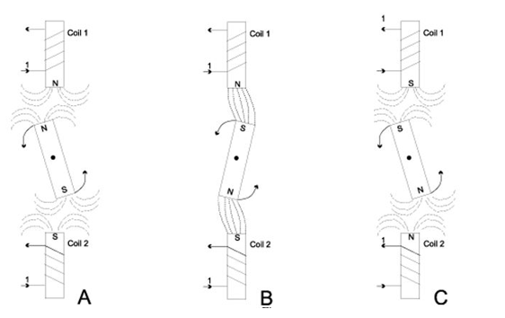
If, however, the direction of currents in the electromagnetic coils was suddenly reversed, thereby reversing the polarity of the two coils, then the poles would again be opposites and repel each other. (Figure C). The movable permanent magnet would then continue to rotate. If the current direction in the electromagnetic coils was changed every time the magnet turned 180 degrees or halfway around, then the magnet would continue to rotate. This simple device is a motor in its simplest form. An actual motor is more complex than the simple device shown above, but the principle is the same.
Electric Generators
Electric generators work on the principle of electromagnetic induction. A conductor coil (a copper coil tightly wound onto a metal core) is rotated rapidly between the poles of a horseshoe type magnet. The conductor coil along with its core is known as an armature. The armature is connected to a shaft of a mechanical energy source such as a motor and rotated. The mechanical energy required can be provided by engines operating on fuels such as diesel, petrol, natural gas, etc. or via renewable energy resources such as a wind turbine, water turbine, solar-powered turbine, etc. When the coil rotates, it cuts the magnetic field which lies between the two poles of the magnet. The magnetic field will interfere with the electrons in the conductor to induce a flow of electric current inside it.
Applications of Electric Generators
- Electric generators are useful for homes, shops, offices, etc. which face frequent power outages. They act as a backup to ensure that the appliances receive uninterrupted power supply.
- In distant areas, where electricity from the main line cannot be accessed, electric generators act as the primary source of power supply.
- When working on project sites where electricity cannot be accessed from the grid, electric generators can be used for power machinery tools
Summary:
Scalar Magnetic Potential is given as: H = - , if J = 0.
Vector Magnetic Potential is given as: B = 
 for line current
 for surface current
 for volume current
Poisson’s equation in homogeneous  medium
Laplace equation  when
when  = 0.
= 0.
Faraday’s Law: The electromagnetic force induces in a closed path or circuit is proportional to the rate of change of magnetic flux enclosed by closed path. e = -N d  / dt volts
Maxwell’s equation  , for a time varying field.
The term Jd = is known as displacement current density and J is the conduction current density (J =
  E).
E).
Maxwell’s equation in final forms:
Differential form | Integral form |
 |  |
 |  |
 |
 |
 |  |
The Poynting vector P, measured in watts per square meter (W/m2) is given as P = E X H.
The Retarded magnetic vector potential at the field point P, due to the dipole, is given by: 
Memristor is a two terminal, charge controlled device. It somewhat acts like a non-linear resistor. It finds it’s applications in DRAM’s.
Electric motors and generators work on the principle of Electromagnetic Induction. Electric motors convert electrical energy into mechanical energy and Generators convert mechanical energy into electrical energy.
References:
1. Kraus and Fleish, “Electromagnetics with Applications”, McGraw Hill International Editions, 5th Edition.
2. Jordan and Balmain, “Electromagnetic Waves and Radiating Systems”, PHI, 1964.
3. Faraday, Maxwell, and the Electromagnetic Field: by Basil Mahon and Nancy Forbes.
4. Electromagnetism: Theory and Applications Book by Ashutosh Pramanik
5. Field and wave electromagnetics Textbook by David K. Cheng