Unit 5
Processor Instructions &Processor Enhancements
Machine Instructions are commands or programs written in machine code of a machine (computer) that it can recognize and execute.
- A machine instruction consists of several bytes in memory that tells the processor to perform one machine operation.
- The processor looks at machine instructions in main memory one after another, and performs one machine operation for each machine instruction.
- The collection of machine instructions in main memory is called a machine language program.
Machine code or machine language is a set of instructions executed directly by a computer’s central processing unit (CPU). Each instruction performs a very specific task, such as a load, a jump, or an ALU operation on a unit of data in a CPU register or memory. Every program directly executed by a CPU is made up of a series of such instructions.
The general format of a machine instruction is
[Label:] Mnemonic [Operand, Operand] [; Comments] |
- Brackets indicate that a field is optional
- Label is an identifier that is assigned the address of the first byte of the instruction in which it appears. It must be followed by “:”
- Inclusion of spaces is arbitrary, except that at least one space must be inserted; no space would lead to an ambiguity.
- Comment field begins with a semicolon “ ; ”
Example:
Here: MOV R5,#25H ;load 25H into R5 |
Machine instructions used in 8086 microprocessor
1. Data transfer instructions– move, load exchange, input, output.
- MOV :Move byte or word to register or memory .
- IN, OUT: Input byte or word from port, output word to port.
- LEA: Load effective address
- LDS, LES Load pointer using data segment, extra segment .
- PUSH, POP: Push word onto stack, pop word off stack.
- XCHG: Exchange byte or word.
- XLAT: Translate byte using look-up table.
2. Arithmetic instructions – add, subtract, increment, decrement, convert byte/word and compare.
- ADD, SUB: Add, subtract byte or word
- ADC, SBB :Add, subtract byte or word and carry (borrow).
- INC, DEC: Increment, decrement byte or word.
- NEG: Negate byte or word (two’s complement).
- CMP: Compare byte or word (subtract without storing).
- MUL, DIV: Multiply, divide byte or word (unsigned).
- IMUL, IDIV: Integer multiply, divide byte or word (signed)
- CBW, CWD: Convert byte to word, word to double word
- AAA, AAS, AAM, AAD: ASCII adjust for add, sub, mul, div .
- DAA, DAS: Decimal adjust for addition, subtraction (BCD numbers)
3. Logic instructions – AND, OR, exclusive OR, shift/rotate and test
- NOT : Logical NOT of byte or word (one’s complement)
- AND: Logical AND of byte or word
- OR: Logical OR of byte or word.
- XOR: Logical exclusive-OR of byte or word
- TEST: Test byte or word (AND without storing).
- SHL, SHR: Logical Shift rotate instruction shift left, right byte or word? by 1or CL
- SAL, SAR: Arithmetic shift left, right byte or word? by 1 or CL
- ROL, ROR: Rotate left, right byte or word? by 1 or CL .
- RCL, RCR: Rotate left, right through carry byte or word? by 1 or CL.
4. String manipulation instruction – load, store, move, compare and scan for byte/word
- MOVS: Move byte or word string
- MOVSB, MOVSW: Move byte, word string.
- CMPS: Compare byte or word string.
- SCAS S: can byte or word string (comparing to A or AX)
- LODS, STOS: Load, store byte or word string to AL.
5. Control transfer instructions – conditional, unconditional, call subroutine and return from subroutine.
- JMP: Unconditional jump .it includes loop transfer and subroutine and interrupt instructions.
- JNZ: jump till the counter value decreases to zero.It runs the loop till the value stored in CX becomes zero
6. Loop control instructions-
- LOOP: Loop unconditional, count in CX, short jump to target address.
- LOOPE (LOOPZ): Loop if equal (zero), count in CX, short jump to target address.
- LOOPNE (LOOPNZ): Loop if not equal (not zero), count in CX, short jump to target address.
- JCXZ: Jump if CX equals zero (used to skip code in loop).
- Subroutine and Interrupt instructions-
- CALL, RET: Call, return from procedure (inside or outside current segment).
- INT, INTO: Software interrupt, interrupt if overflow. RET: Return from interrupt.
7. Processor control instructions-
Flag manipulation:
- STC, CLC, CMC: Set, clear, complement carry flag.
- STD, CLD: Set, clear direction flag.STI, CLI: Set, clear interrupt enable flag.
- PUSHF, POPF: Push flags onto stack, pop flags off stack.
What is an Instruction Set?
From the designer's point of view, the machine instruction set provides the functional requirements for the CPU: Implementing the CPU is a task that in large part involves implementing the machine instruction set.
From the user's side, the user who chooses to program in machine language (actually, in assembly language) becomes aware of the register and memory structure, the types of data directly supported by the machine, and the functioning of the ALU.
Elements of an Instruction
Each instruction must have elements that contain the information required by the CPU for execution. These elements are as follows
- Operation code: Specifies the operation to be performed (e.g.. ADD, I/O). The operation is specified by a binary code, known as the operation code, or opcode.
- Source operand reference: The operation may involve one or more source operands, that is, operands that are inputs for the operation.
- Result operand reference: The operation may produce a result.
- Next instruction reference: This tells the CPU where to fetch the next instruction after the execution of this instruction is complete.
The next instruction to be fetched is located in main memory or, in the case of a virtual memory system, in either main memory or secondary memory (disk). In most cases, the next instruction to be fetched immediately follows the current instruction. In those cases, there is no explicit reference to the next instruction. Source and result operands can be in one of three areas:
- Main or virtual memory: As with next instruction references, the main or virtual memory address must be supplied.
- CPU register: With rare exceptions, a CPU contains one or more registers that may be referenced by machine instructions. If only one register exists, reference to it may be implicit. If more than one register exists, then each register is assigned a unique number, and the instruction must contain the number of the desired register.
- I/O device: The instruction must specify (he I/O module and device for the operation. If memory-mapped I/O is used, this is just another main or virtual memory address.
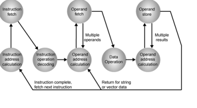
Instruction Cycle State Diagram
Instruction Representation
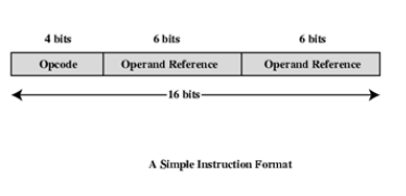
Within the computer, each instruction is represented by a sequence of bits. The instruction is divided into fields, corresponding to the constituent elements of the instruction. During instruction execution, an instruction is read into an instruction register (IR) in the CPU. The CPU must be able to extract the data from the various instruction fields to perform the required operation.
It is difficult for both the programmer and the reader of textbooks to deal with binary representations of machine instructions. Thus, it has become common practice to use a symbolic representation of machine instructions. Opcodes are represented by abbreviations, called mnemonics, that indicate the operation. Common examples include
ADD | Add |
SUB | Subtract |
MPY | Multiply |
DIV | Divide |
LOAD | Load data from memory |
STOR | Store data to memory |
Operands are also represented symbolically. For example, the instruction
ADD R, Y
May mean add the value contained in data location Y to the contents of register R. In this example. Y refers to the address of a location in memory, and R refers to a particular register. Note that the operation is performed on the contents of a location, not on its address.
Simple Instruction Format
Instruction Types
Consider a high-level language instruction that could be expressed in a language such as BASIC or FORTRAN. For example,
X = X+Y
This statement instructs the computer lo add the value stored in Y to the value Stored in X and put the result in X. How might this be accomplished with machine instructions? Let us assume that the variables X and Y correspond lo locations 513 and 514. If we assume a simple set of machine instructions, this operation could be accomplished with three instructions:
1. Load a register with the contents of memory location 513.
2. Add the contents of memory location 514 to the register.
3. Store the contents of the register in memory location 513.
As can be seen, the single BASIC instruction may require three machine instructions. This is typical of the relationship between a high-level language and a machine language. A high-level language expresses operations in a concise algebraic form, using variables. A machine language expresses operations in a basic form involving the movement of data to or from registers.
With this simple example to guide us, let us consider the types of instructions that must be included in a practical computer. A computer should have a set of instructions that allows the user to formulate any data processing task. Another way to view it is to consider the capabilities of a high-level programming language. Any program written in a high-level language must be translated into machine language to be executed. Thus, the set of machine instructions must be sufficient to express any of the instructions from a high-level language. With this in mind we can categorize instruction types as follows:
- Data processing: Arithmetic and logic instructions
- Data storage: Memory instructions
- Data movement: I/O instructions
- Control: Test and branch instructions
Number of Addresses
What is the maximum number of addresses one might need in an instruction? Evidently, arithmetic and logic instructions will require the most operands. Virtually all arithmetic and logic operations are either unary (one operand) or binary (two operands). Thus, we would need a maximum of two addresses to reference operands. The result of an operation must be stored, suggesting a third address. Finally, after completion of an instruction, the next instruction must be fetched, and its address is needed.
This line of reasoning suggests that an instruction could plausibly be required to contain four address references: two operands, one result and the address of the next instruction. In practice, four-address instructions are extremely rare. Most instructions have one, two, or three operand addresses, with the address of the next instruction being implicit (obtained from the program counter).
- Three addresses:
- Operand 1, Operand 2, Result
Example: a = b + c
- Three-address instruction formats are not common, because they require a relatively long instruction format to hold the three address references.
- Two addresses:
- One address doubles as operand and result
Example: a = a + b
- The two-address formal reduces the space requirement but also introduces some awkwardness. To avoid altering the value of an operand, a MOVE instruction is used to move one of the values to a result or temporary location before performing the operation.
- One addresses:
- a second address must be implicit. This was common in earlier machines, with the implied address being a CPU register known as the accumulator. Or AC. The accumulator contains one of the operands and is used to store the result.
- Zero addresses
- Zero-address instructions are applicable to a special memory organization, called a Stack. A stack is a last-in-first-out set of locations.
How Many Addresses?
The number of addresses per instruction is a basic design decision.
Fewer addresses:
- Fewer addresses per instruction result in more primitive instructions, which requires a less complex CPU.
- It also results in instructions of shorter length. On the other hand, programs contain more total instructions, which in general results in longer execution times and longer, more complex programs
Multiple-address instructions:
- With multiple-address instructions, it is common to have multiple general-purpose registers. This allows some operations to be performed solely on registers.
- Because register references are faster than memory references, this speeds up execution.
Design Decisions
One of the most interesting and most analysed, aspects of computer design is instruction set design. The design of an instruction set is very complex, because it affects so many aspects of the computer system. The instruction set defines many of the functions performed by the CPU and thus has a significant effect on the implementation of the CPU. The instruction set is the programmer's means of controlling the CPU. Thus, programmer requirements must be considered in designing the instruction set. The most important design issues include the following:
- Operation repertoire: How many and which operations to provide, and how complex operations should be
- Data types: The various types of data upon which operations are performed
- Instruction format: Instruction length (in bits), number of addresses, size of various fields, and so on.
- Registers: Number of CPU registers that can be referenced by instructions, and their use.
- Addressing: The mode or modes by which the address of an operand is specified
Types of Operands
Machine instructions operate on data. The most important general categories of data are:
- Addresses
- Numbers
- Characters
- Logical data
Numbers
All machine languages include numeric data types. Even in nonnumeric data processing, there is a need for numbers to act as counters, field widths, and so forth. An important distinction between numbers used in ordinary mathematics and numbers stored in a computer is that the latter are limited. Thus, the programmer is faced with understanding the consequences of rounding, overflow and underflow.
Three types of numerical data are common in computers:
- Integer or fixed point
- Floating point
- Decimal
Characters
A common form of data is text or character strings. While textual data are most convenient for human beings, they cannot, in character form, be easily stored or transmitted by data processing and communications systems. Such systems are designed for binary data. Thus, a number of codes have been devised by which characters are represented by a sequence of bits. Perhaps the earliest common example of this is the Morse code. Today, the most commonly used character code in the International Reference Alphabet (IRA), referred to in the United States as the American Standard Code for Information Interchange (ASCII). IRA is also widely used outside the United States. Each character in this code is represented by a unique 7-bit pattern, thus, 128 different characters can be represented. This is a larger number than is necessary to represent printable characters, and some of the patterns represent control characters. Some of these control characters have to do with controlling the printing of characters on a page. Others are concerned with communications procedures. IRA-encoded characters are almost always stored and transmitted using 8 bits per character. The eighth bit may be set to 0 or used as a parity bit for error detection. In the latter case, the bit is set such that the total number of binary 1s in each octet is always odd (odd parity) or always even (even parity).
Another code used to encode characters is the Extended Binary Coded Decimal Interchange Code (EBCDIC). EBCDIC is used on IBM S/390 machines. It is an 8-bit code. As with IRA, EBCDIC is compatible with packed decimal. In the case of EBCDIC, the codes 11110000 through 11111001 represent the digits 0 through 9.
Logical Data
Normally, each word or other addressable unit (byte, half-word, and soon) is treated as a single unit of data. It is sometimes useful, however, to consider an n-bit unit as consisting 1-bit items of data, each item having the value 0 or I. When data are viewed this way, they are considered to be logic data.
There are two advantages to the bit-oriented view:
- First, we may sometimes wish to store an array of Boolean or binary data items, in which each item can take on only the values I (true) and II (fake). With logical data, memory can be used most efficiently for this storage.
- Second, there are occasions when we wish to manipulate the bits of a data item.
Types of Operations
The number of different opcodes varies widely from machine to machine. However, the same general types of operations are found on all machines. A useful and typical categorization is the following:
- Data transfer
- Arithmetic
- Logical
- Conversion
- I/O
- System control
- Transfer of control
Data transfer
The most fundamental type of machine instruction is the data transfer instruction. The data transfer instruction must specify several things.
- The location of the source and destination operands must be specified. Each location could be memory. a register, or the lop of the stack.
- The length of data to be transferred must be indicated.
- As with all instructions with operands, the mode of addressing for each operand must be specified.
In term of CPU action, data transfer operations are perhaps the simplest type. If both source and destination are registers, then the CPU simply causes data to be transferred from one register to another; this is an operation internal to the CPU. If one or both operands are in memory, then (he CPU must perform some or all of following actions:
1. Calculate the memory address, based on the address mode
2. If the address refers to virtual memory, translate from virtual to actual memory address.
3. Determine whether the addressed item is in cache.
4. If not, issue a command lo the memory module.
Example:
Operation mnemonic | Name | Number of bits transferred | Description |
L | Load | 32 | Transfer from memory in register |
LH | Load half-word | 16 | Transler from memory to register |
ST | Store | 32 | Transfer from register to memory |
STH | Store half-word | 16 | Transfer from register to memory |
Arithmetic
Most machines provide the basic arithmetic operations of add, subtract, multiply, and divide. These are invariably provided for signed integer (fixed-point) numbers, Often they are also provided for floating-point and packed decimal numbers.
Other possible operations include a variety of single-operand instructions: for example.
• Absolute: Take the absolute value of the operand.
• Negate: Negate the Operand.
• Increment.: Add 1 to the operand.
• Decrement: Subtract 1 from the operand
Logical
Most machines also provide a variety of operations for manipulating individual bits of a word or other addressable units, often referred to as "bit twiddling." They are based upon Boolean operations.
Some of the basic logical operations that can be performed on Boolean or binary data are AND, OR, NOT, XOR, …
These logical operations can be applied bitwise to n-bit logical data units. Thus, if two registers contain the data
(R1) - 10100101 (R2) - 00001111
Then
(R1) AND (R2) – 00000101
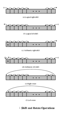
In addition lo bitwise logical operations, most machines provide a variety of shifting and rotating functions such as shift left, shift right, right rotate, left rotate…
Conversion
Conversion instructions are those that change the format or operate on the format of data. An example is converting from decimal to binary.
Input/output
As we saw, there are a variety of approaches taken, including isolated programmed IO, memory-mapped programmed I/O, DMA, and the use of an I/O processor. Many implementations provide only a few I/O instructions, with the specific actions specified by parameters, codes, or command words.
System Controls
System control instructions are those that can he executed only while the processor is in a certain privileged state or is executing a program in a special privileged area of memory, typically, these instructions are reserved for the use of the operating system.
Some examples of system control operations are as follows. A system control instruction may read or alter a control register. Another example is an instruction to read or modify a storage protection key, such us is used in the S/390 memory system. Another example is access to process control blocks in a multiprogramming system.
Transfer of control
For all of the operation types discussed so far. The next instruction to be performed is the one that immediately follows, in memory, the current instruction. However, a significant fraction of the instructions in any program have as their function changing the sequence of instruction execution. For these instructions, the operation performed by the CPU is to update the program counter to contain the address of some instruction in memory.
There are a number of reasons why transfer-of-control operations are required. Among the most important are the following:
1. In the practical use of computers, it is essential to be able to execute each instruction more than once and perhaps many thousands of times. It may require thousands or perhaps millions of instructions to implement an application. This would be unthinkable if each instruction had to be written out separately. If a table or a list of items is to be processed, a program loop is needed. One sequence of instructions is executed repeatedly to process all the data.
2. Virtually all programs involve some decision making. We would like the computer to do one thing if one condition holds, and another thing if another condition holds. For example, a sequence of instructions computes the square root of a number. At the start of the sequence, the sign of the number is tested, If the number is negative, the computation is not performed, but an error condition is reported.
3. To compose correctly a large or even medium-size computer program is an exceedingly difficult task. It helps if there are mechanisms for breaking the task up into smaller pieces that can be worked on one at a time.
We now turn to a discussion of the most common transfer-of-control operations found in instruction sets: branch, skip, and procedure call.
Branch instruction
A branch instruction, also called a jump instruction, has as one of its operands the address of the next instruction to be executed. Most often, the instruction is a conditional branch instruction. That is, the branch is made (update program counter to equal address specified in operand) only if a certain condition is met. Otherwise, the next instruction in sequence is executed (increment program counter as usual).
Skip instructions
Another common form of transfer-of-control instruction is the skip instruction. The skip instruction includes an implied address. Typically, the skip implies that one instruction be skipped; thus, the implied address equals the address of the next instruction plus one instruction-length.
Procedure call instructions
Perhaps the most important innovation in the development of programming languages is the procedure, a procedure is a self-contained computer program that is incorporated into a larger program. At any point in the program the procedure may he invoked, or called. The processor is instructed to go and execute the entire procedure and then return to the point from which the call took place.
The two principal reasons for the use of procedures are economy and modularity. A procedure allows the same piece of code to be used many times. This is important for economy in programming effort and for making the most efficient use of storage space in the system (the program must be stored). Procedures also allow large programming tasks to be subdivided into smaller units. This use of modularity greatly eases the programming task.
The procedure mechanism involves two basic instructions: a call instruction that branches from the present location to the procedure, and a return instruction that returns from the procedure to the place from which it was called. Both of these are forms of branching instructions.
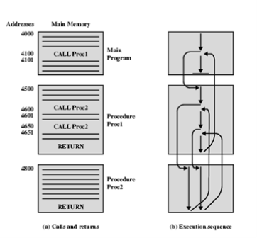
The above figure illustrates the use of procedures to construct a program. In this example, there is a main program starting at location 4000. This program includes a call to procedure PROC1, starting at location 4500. When this call instruction is encountered, the CPU suspends execution of the main program and begins execution of PROC1 by fetching the next instruction from location 4500. Within PROC1, there are two calls to PR0C2 at location 4800. In each case, the execution of PROC1 is suspended and PROC2 is executed. The RETURN statement causes the CPU to go back to the calling program and continue execution at the instruction after the corresponding CALL instruction. This behavior is illustrated in the right of this figure.
Several points are worth noting:
1. A procedure can be called from more than one location.
2. A procedure call can appear in a procedure. This allows the nesting of procedures to an arbitrary depth.
3. Each procedure call is matched by a return in the called program.
Because we would like to be able to call a procedure from a variety of points, the CPU must somehow save the return address so that the return can take place appropriately. There are three common places for storing the return address:
• Register
• Start of called procedure
• Top of stack
Addressing Modes
The address field or fields in a typical instruction format are relatively small. We would like to be able to reference a large range of locations in main memory or for some systems, virtual memory. To achieve this objective, a variety of addressing techniques has been employed. They all involve some trade-off between address range and/or addressing flexibility, on the one hand, and the number of memory references and/or the complexity of address calculation, on the other. In this section, we examine the most common addressing techniques:
- Immediate
- Direct
- Indirect
- Register
- Register indirect
- Displacement
Immediate Addressing
The simplest form of addressing is immediate addressing, in which the operand is actually present in the instruction:
- Operand is part of instruction
- Operand = address field
- e.g. ADD 5 ;Add 5 to contents of accumulator ;5 is operand

The advantage of immediate addressing is that no memory reference other than the instruction fetch is required to obtain the operand, thus saving one memory or cache cycle in the instruction cycle.
The disadvantage is that the size of the number is restricted to the size of the address field, which, in most instruction sets, is small compared with the word length.
Direct Addressing
A very simple form of addressing is direct addressing, in which:
- Address field contains address of operand
- Effective address (EA) = address field (A)
- e.g. ADD A ;Add contents of cell A to accumulator
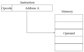
The technique was common in earlier generations of computers but is not common on contemporary architectures. It requires only one memory reference and no special calculation. The obvious limitation is that it provides only a limited address space.
Indirect Addressing
With direct addressing, the length of the address field is usually less than the word length, thus limiting the address range. One solution is to have the address field refer to the address of a word in memory, which in turn contains a full-length address of the operand. This is known as indirect addressing.
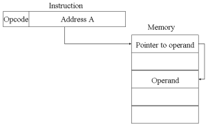
Register Addressing
Register addressing is similar to direct addressing. The only difference is that the address field refers to a register rather than a main memory address.
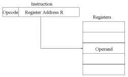
The advantages of register addressing are that :
- Only a small address field is needed in the instruction
- No memory 'references are required, faster instruction fetch
The disadvantage of register addressing is that the address space is very limited.
Register Indirect Addressing
Just as register addressing is analogous to direct addressing, register indirect addressing is analogous to indirect addressing. In both cases, the only difference is whether the address field refers to a memory location or a register. Thus, for register indirect address: Operand is in memory cell pointed to by contents of register.
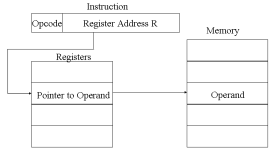
The advantages and limitations of register indirect addressing are basically the same as for indirect addressing. In both cases, the address space limitation (limited range of addresses) of the address field is overcome by having that field refer to a word-length location containing an address. In addition, register indirect addressing uses one less memory reference than indirect addressing.
Displacement Addressing
A very powerful mode of addressing combines the capabilities of direct addressing and register indirect addressing. It is known by a variety of names depending on the context of its use but the basic mechanism is the same. We will refer to this as displacement addressing, address field hold two values:
- A = base value
- R = register that holds displacement
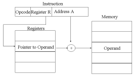
Computer perform task on the basis of instruction provided. An instruction in computer comprises of groups called fields. These field contains different information as for computers every thing is in 0 and 1 so each field has different significance on the basis of which a CPU decide what to perform. The most common fields are:
- Operation field which specifies the operation to be performed like addition.
- Address field which contain the location of operand, i.e., register or memory location.
- Mode field which specifies how operand is to be founded.
An instruction is of various length depending upon the number of addresses it contain. Generally CPU organization are of three types on the basis of number of address fields:
- Single Accumulator organization
- General register organization
- Stack organization
In first organization operation is done involving a special register called accumulator. In second on multiple registers are used for the computation purpose. In third organization the work on stack basis operation due to which it does not contain any address field. It is not necessary that only a single organization is applied a blend of various organization is mostly what we see generally.
On the basis of number of address, instruction are classified as:
Note that we will use X = (A+B)*(C+D) expression to showcase the procedure.
- Zero Address Instructions –
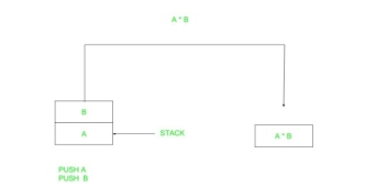
A stack based computer do not use address field in instruction. To evaluate a expression first it is converted to revere Polish Notation i.e. Post fix Notation.
Expression: X = (A+B)*(C+D)
Postfixed : X = AB+CD+*
TOP means top of stack
M[X] is any memory location
PUSH | A | TOP = A |
PUSH | B | TOP = B |
ADD |
| TOP = A+B |
PUSH | C | TOP = C |
PUSH | D | TOP = D |
ADD |
| TOP = C+D |
MUL |
| TOP = (C+D)*(A+B) |
POP | X | M[X] = TOP |
2. One Address Instructions –
This use a implied ACCUMULATOR register for data manipulation.One operand is in accumulator and other is in register or memory location.Implied means that the CPU already know that one operand is in accumulator so there is no need to specify it.

Expression: X = (A+B)*(C+D)
AC is accumulator
M[] is any memory location
M[T] is temporary location
LOAD | A | AC = M[A] |
ADD | B | AC = AC + M[B] |
STORE | T | M[T] = AC |
LOAD | C | AC = M[C] |
ADD | D | AC = AC + M[D] |
MUL | T | AC = AC * M[T] |
STORE | X | M[X] = AC |
3. Two Address Instructions –
This is common in commercial computers. Here two address can be specified in the instruction. Unlike earlier in one address instruction the result was stored in accumulator here result cab be stored at different location rather than just accumulator, but require more number of bit to represent address.

Here destination address can also contain operand.
Expression: X = (A+B)*(C+D)
R1, R2 are registers
M[] is any memory location
MOV | R1, A | R1 = M[A] |
ADD | R1, B | R1 = R1 + M[B] |
MOV | R2, C | R2 = C |
ADD | R2, D | R2 = R2 + D |
MUL | R1, R2 | R1 = R1 * R2 |
MOV | X, R1 | M[X] = R1 |
4. Three Address Instructions –
This has three address field to specify a register or a memory location. Program created are much short in size but number of bits per instruction increase. These instructions make creation of program much easier but it does not mean that program will run much faster because now instruction only contain more information but each micro operation (changing content of register, loading address in address bus etc.) will be performed in one cycle only.

Expression: X = (A+B)*(C+D)
R1, R2 are registers
M[] is any memory location
ADD | R1, A, B | R1 = M[A] + M[B] |
ADD | R2, C, D | R2 = M[C] + M[D] |
MUL | X, R1, R2 | M[X] = R1 * R2 |
Machine instructions operate on data. The most important general categories of data are:
- Addresses
- Numbers
- Characters
- Logical data
1) Numbers:
All machine languages include numeric data types. Even in nonnumeric data processing, there is a need for numbers to act as counters, field widths, and so forth. An important distinction between numbers used in ordinary mathematics and numbers stored in a computer is that the latter are limited. Thus, the programmer is faced with understanding the consequences of rounding, overflow and underflow.
Three types of numerical data are common in computers:
- Integer or fixed point
- Floating point
- Decimal
2) Characters:
A common form of data is text or character strings. While textual data are most convenient for human beings, they cannot, in character form, be easily stored or transmitted by data processing and communications systems. Such systems are designed for binary data. Thus, a number of codes have been devised by which characters are represented by a sequence of bits. Perhaps the earliest common example of this is the Morse code. Today, the most commonly used character code in the International Reference Alphabet (IRA), referred to in the United States as the American Standard Code for Information Interchange (ASCII). IRA is also widely used outside the United States. Each character in this code is represented by a unique 7-bit pattern, thus, 128 different characters can be represented. This is a larger number than is necessary to represent printable characters, and some of the patterns represent control characters. Some of these control characters have to do with controlling the printing of characters on a page. Others are concerned with communications procedures. IRA-encoded characters are almost always stored and transmitted using 8 bits per character. The eighth bit may be set to 0 or used as a parity bit for error detection. In the latter case, the bit is set such that the total number of binary 1s in each octet is always odd (odd parity) or always even (even parity). Another code used to encode characters is the Extended Binary Coded Decimal Interchange Code (EBCDIC). EBCDIC is used on IBM S/390 machines. It is an 8-bit code. As with IRA, EBCDIC is compatible with packed decimal. In the case of EBCDIC, the codes 11110000 through 11111001 represent the digits 0 through 9.
3) Logical data:
Normally, each word or other addressable unit (byte, half-word, and soon) is treated as a single unit of data. It is sometimes useful, however, to consider an n-bit unit as consisting 1-bit items of data, each item having the value 0 or I. When data are viewed this way, they are considered to be logic data.
There are two advantages to the bit-oriented view:
- First, we may sometimes wish to store an array of Boolean or binary data items, in which each item can take on only the values I (true) and II (fake). With logical data, memory can be used most efficiently for this storage.
- Second, there are occasions when we wish to manipulate the bits of a data item.
Addressing Modes– The term addressing modes refers to the way in which the operand of an instruction is specified. The addressing mode specifies a rule for interpreting or modifying the address field of the instruction before the operand is actually executed.
Addressing modes for 8086 instructions are divided into two categories:
1) Addressing modes for data
2) Addressing modes for branch
The 8086 memory addressing modes provide flexible access to memory, allowing you to easily access variables, arrays, records, pointers, and other complex data types. The key to good assembly language programming is the proper use of memory addressing modes.
An assembly language program instruction consists of two parts

The memory address of an operand consists of two components:
IMPORTANT TERMS
- Starting address of memory segment.
- Effective address or Offset: An offset is determined by adding any combination of three address elements: displacement, base and index.
- Displacement: It is an 8 bit or 16 bit immediate value given in the instruction.
- Base: Contents of base register, BX or BP.
- Index: Content of index register SI or DI.
According to different ways of specifying an operand by 8086 microprocessor, different addressing modes are used by 8086.
Addressing modes used by 8086 microprocessor are discussed below:
- Implied mode:: In implied addressing the operand is specified in the instruction itself. In this mode the data is 8 bits or 16 bits long and data is the part of instruction. Zero address instruction are designed with implied addressing mode.

Example: CLC (used to reset Carry flag to 0)
- Immediate addressing mode (symbol #):In this mode data is present in address field of instruction .Designed like one address instruction format.
Note: Limitation in the immediate mode is that the range of constants are restricted by size of address field.
Example: MOV AL, 35H (move the data 35H into AL register)
- Register mode: In register addressing the operand is placed in one of 8 bit or 16 bit general purpose registers. The data is in the register that is specified by the instruction.
Here one register reference is required to access the data.
Example: MOV AX,CX (move the contents of CX register to AX register)
- Register Indirect mode: In this addressing the operand’s offset is placed in any one of the registers BX,BP,SI,DI as specified in the instruction. The effective address of the data is in the base register or an index register that is specified by the instruction.
Here two register reference is required to access the data.
The 8086 CPUs let you access memory indirectly through a register using the register indirect addressing modes. - MOV AX, [BX](move the contents of memory location s
Addressed by the register BX to the register AX)
- Auto Indexed (increment mode): Effective address of the operand is the contents of a register specified in the instruction. After accessing the operand, the contents of this register are automatically incremented to point to the next consecutive memory location.(R1)+.
Here one register reference, one memory reference and one ALU operation is required to access the data.
Example: - Add R1, (R2)+ // OR
- R1 = R1 +M[R2]
R2 = R2 + d
Useful for stepping through arrays in a loop. R2 – start of array d – size of an element
- Auto indexed ( decrement mode): Effective address of the operand is the contents of a register specified in the instruction. Before accessing the operand, the contents of this register are automatically decremented to point to the previous consecutive memory location. –(R1)
Here one register reference,one memory reference and one ALU operation is required to access the data.
Example:
Add R1,-(R2) //OR
R2 = R2-d
R1 = R1 + M[R2]
Auto decrement mode is same as auto increment mode. Both can also be used to implement a stack as push and pop . Auto increment and Auto decrement modes are useful for implementing “Last-In-First-Out” data structures.
- Direct addressing/ Absolute addressing Mode (symbol [ ]): The operand’s offset is given in the instruction as an 8 bit or 16 bit displacement element. In this addressing mode the 16 bit effective address of the data is the part of the instruction.
Here only one memory reference operation is required to access the data.

Example: ADD AL,[0301] //add the contents of offset address 0301 to AL
- Indirect addressing Mode (symbol @ or () ):In this mode address field of instruction contains the address of effective address. Here two references are required.
1st reference to get effective address.
2nd reference to access the data.
Based on the availability of Effective address, Indirect mode is of two kind:
- Register Indirect:In this mode effective address is in the register, and corresponding register name will be maintained in the address field of an instruction.
Here one register reference, one memory reference is required to access the data. - Memory Indirect: In this mode effective address is in the memory, and corresponding memory address will be maintained in the address field of an instruction.
Here two memory reference is required to access the data.
- Indexed addressing mode: The operand’s offset is the sum of the content of an index register SI or DI and an 8 bit or 16 bit displacement.
Example:MOV AX, [SI +05]
- Based Indexed Addressing: The operand’s offset is sum of the content of a base register BX or BP and an index register SI or DI.
Example: ADD AX, [BX+SI]
Based on Transfer of control, addressing modes are:
- PC relative addressing mode: PC relative addressing mode is used to implement intra segment transfer of control, In this mode effective address is obtained by adding displacement to PC.
- EA= PC + Address field value
PC= PC + Relative value.
3. Base register addressing mode: Base register addressing mode is used to implement inter segment transfer of control. In this mode effective address is obtained by adding base register value to address field value.
4. EA= Base register + Address field value.
5. PC= Base register + Relative value.
Note:
- PC relative nad based register both addressing modes are suitable for program relocation at runtime.
- Based register addressing mode is best suitable to write position independent codes.
Advantages of Addressing Modes
To give programmers to facilities such as Pointers, counters for loop controls, indexing of data and program relocation.
To reduce the number bits in the addressing field of the Instruction.
Instruction Set Operations
- Arithmetic/Logical : Integer ALU ops.
- ADD , AND , SUB , OR .
- Load/Stores : Data transfer between memory and registers.
- LOAD , STORE (Reg-reg), MOVE (Mem-mem)
- Control : Instructions to change the program execution sequence.
- BEQZ , BNEQ , JMP , CALL , RETURN , TRAP
- System : OS instructions, virtual memory management instructions.
- INT
- Floating Point :
- FADD , FMULT
- Decimal : Support for BSD
- String : Special instruction optimized for handling ASCII character strings.
- Graphics : Pixel operations, compression and decompression.
Instruction Set Operations
- All machines generally provide a full set of operations for the first three categories.
- All machines MUST provide instruction support for basic system functions.
- Floating point instructions are optional but are commonly provided.
- Decimal and string instructions are optional but are disappearing in recent ISAs. They can be easily emulated by sequences of simpler instructions.
- Graphic instructions are optional.
- Remember MAKE THE COMMON CASE FAST ?
ALU and Load/Store instructions represent a significant portion of the instruction mix and therefore should execute quickly.
Instruction Set Operations
- Control Flow instructions:
Four types are identifiable:
- Conditional branches
- Jumps
- Procedure Calls
- Procedure Returns
- Program analysis shows that Conditional branches dominate (> 80% ).
- The destination address must always be specified.
- In most cases, it is given explicitly in the instruction.
- Exception: Procedure return addresses are not known at compile time.
Control Flow Operations
- Addressing Modes:
- PC-relative : Most common.
- Constant in instruction gives the offset to be added to the PC.
- Adv:
- Since target is often near the current instruction, the displacement can be small, requiring few address bits.
- Allows relocatable (position independent) code.
- Indirect (jump to the address given by a register).
- For procedure returns and indirect jumps for which the address is not known at compile time.
- Register indirect jumps useful for three important features:
- Case or switch statements.
- Dynamic shared libraries
- Virtual functions.
- Absolute (jump to location in memory). Not commonly used.
Control Flow Operations
- Conditional branches:
- Issue: What is the appropriate field size for the offset ?
- Important because it affects instruction length and encoding.
- Issue: What is the appropriate field size for the offset ?
- Observations:
- Most frequent branches for integer programs are targets 4 to 7 instructions away (for DLX). This suggests a small offset field is sufficient.
- Most non-loop branches ( up to 75% of all branches) are forward. However, they are hard to "predict" and optimize.
- Most loop branches are backward. Backward branches are usually taken, since they are usually part of loops.
Control Flow Operations
- Conditional branches: Methods of testing the condition:
- Condition Codes (CC) :
- Special bits are set by ALU operations as a side effect.
- Adv:
- Reduces instruction count - it's done for free.
- Disadv:
- Extra state that must be implemented.
- More importantly, it constrains the ordering of instructions (no intervening instructions allowed (that set the CC) between the instruction that sets the CC and the branch that tests the CC).
- Condition register :
- Comparisons leave result in a register, which is tested later.
- Compare and branch :
- Similar to b, but allows more complex comparisons in the branch.
- Sometimes, this is too complex.
Control Flow Operations
- Subroutines: Include control transfer and return + some state saving.
- Should architecture save registers or should compiler do it ?
- Caller saving : Caller saves any registers that it wants to use after the call.
- Callee saving : Callee saves the registers.
- Compiler must determine if procedures may access (global) register-allocated quantities.
This determination is complicated by separate compilation.
- Optimal solution in many cases is to have compiler use both conventions.
- Implementing sophisticated instructions to do the saving is often in contradiction with the optimal solution.
Type and Size of Operands and Encoding an Instruction Set
- Size and Type of Operands summary :
Frequency of use data indicates that a new 64 bit architecture should support 8 , 16 , 32 and 64 bit integers and 64-bit IEEE 754 floating point data.
- Encoding summary :
An architect more interested in code size will pick variable encoding.
Allows virtually all addressing modes in all operations.
This style is best when there are lots of addressing modes and operations.
Instruction differ significantly in the amount of work performed.
An architect more interested in simplifying instruction decoding in the CPU will pick fixed encoding.
Operation and addressing mode encoded into the opcode.
Reduced Set Instruction Set Architecture (RISC) –
The main idea behind is to make hardware simpler by using an instruction set composed of a few basic steps for loading, evaluating and storing operations just like a load command will load data, store command will store the data.
Complex Instruction Set Architecture (CISC) –
The main idea is that a single instruction will do all loading, evaluating and storing operations just like a multiplication command will do stuff like loading data, evaluating and storing it, hence it’s complex.
Both approaches try to increase the CPU performance
- RISC: Reduce the cycles per instruction at the cost of the number of instructions per program.
- CISC: The CISC approach attempts to minimize the number of instructions per program but at the cost of increase in number of cycles per instruction.

Earlier when programming was done using assembly language, a need was felt to make instruction do more task because programming in assembly was tedious and error prone due to which CISC architecture evolved but with uprise of high level language dependency on assembly reduced RISC architecture prevailed.
Characteristic of RISC –
- Simpler instruction, hence simple instruction decoding.
- Instruction come under size of one word.
- Instruction take single clock cycle to get executed.
- More number of general purpose register.
- Simple Addressing Modes.
- Less Data types.
- Pipeling can be achieved.
Characteristic of CISC –
- Complex instruction, hence complex instruction decoding.
- Instruction are larger than one word size.
- Instruction may take more than single clock cycle to get executed.
- Less number of general purpose register as operation get performed in memory itself.
- Complex Addressing Modes.
- More Data types.
Example – Suppose we have to add two 8-bit number:
- CISC approach: There will be a single command or instruction for this like ADD which will perform the task.
- RISC approach: Here programmer will write first load command to load data in registers then it will use suitable operator and then it will store result in desired location.
So, add operation is divided into parts i.e. load, operate, store due to which RISC programs are longer and require more memory to get stored but require less transistors due to less complex command.
Difference –
RISC | CISC |
Focus on software | Focus on hardware |
Uses only Hardwired control unit | Uses both hardwired and micro programmed control unit |
Transistors are used for more registers | Transistors are used for storing complex |
Fixed sized instructions | Variable sized instructions |
Can perform only Register to Register Arithmetic operations | Can perform REG to REG or REG to MEM or MEM to MEM |
Requires more number of registers | Requires less number of registers |
Code size is large | Code size is small |
A instruction execute in single clock cycle | Instruction take more than one clock cycle |
A instruction fit in one word | Instruction are larger than size of one word |
Most exceptions are handled simply by sending a Unix signal to the process that caused the exception. The action to be taken is thus deferred until the process receives the signal; as a result, the kernel is able to process the exception quickly.
This approach does not hold for interrupts, because they frequently arrive long after the process to which they are related (for instance, a process that requested a data transfer) has been suspended and a completely unrelated process is running. So it would make no sense to send a Unix signal to the current process.
Interrupt handling depends on the type of interrupt. For our purposes, we’ll distinguish three main classes of interrupts:
I/O interrupts
An I/O device requires attention; the corresponding interrupt handler must query the device to determine the proper course of action.
Timer interrupts
Some timer, either a local APIC timer or an external timer, has issued an interrupt; this kind of interrupt tells the kernel that a fixed-time interval has elapsed. These interrupts are handled mostly as I/O interrupts;
Interprocessor interrupts
A CPU issued an interrupt to another CPU of a multiprocessor system.
I/O Interrupt Handling
In general, an I/O interrupt handler must be flexible enough to service several devices at the same time. In the PCI bus architecture, for instance, several devices may share the same IRQ line. This means that the interrupt vector alone does not tell the whole story. In the example shown the same vector 43 is assigned to the USB port and to the sound card. However, some hardware devices found in older PC architectures (such as ISA) do not reliably operate if their IRQ line is shared with other devices.
Interrupt handler flexibility is achieved in two distinct ways, as discussed in the following list.
IRQ sharing
The interrupt handler executes several interrupt service routines (ISRs). Each ISR is a function related to a single device sharing the IRQ line. Because it is not possible to know in advance which particular device issued the IRQ, each ISR is executed to verify whether its device needs attention; if so, the ISR performs all the operations that need to be executed when the device raises an interrupt.
IRQ dynamic allocation
An IRQ line is associated with a device driver at the last possible moment; for instance, the IRQ line of the floppy device is allocated only when a user accesses the floppy disk device. In this way, the same IRQ vector may be used by several hardware devices even if they cannot share the IRQ line; of course, the hardware devices cannot be used at the same time. (See the discussion at the end of this section.)
Not all actions to be performed when an interrupt occurs have the same urgency. In fact, the interrupt handler itself is not a suitable place for all kind of actions. Long noncritical operations should be deferred, because while an interrupt handler is running, the signals on the corresponding IRQ line are temporarily ignored. Most important, the process on behalf of which an interrupt handler is executed must always stay in the TASK_RUNNING state, or a system freeze can occur. Therefore, interrupt handlers cannot perform any blocking procedure such as an I/O disk operation. Linux divides the actions to be performed following an interrupt into three classes:
Critical
Actions such as acknowledging an interrupt to the PIC, reprogramming the PIC or the device controller, or updating data structures accessed by both the device and the processor. These can be executed quickly and are critical, because they must be performed as soon as possible. Critical actions are executed within the interrupt handler immediately, with maskable interrupts disabled.
Noncritical
Actions such as updating data structures that are accessed only by the processor (for instance, reading the scan code after a keyboard key has been pushed). These actions can also finish quickly, so they are executed by the interrupt handler immediately, with the interrupts enabled.
Noncritical deferrable
Actions such as copying a buffer’s contents into the address space of a process (for instance, sending the keyboard line buffer to the terminal handler process). These may be delayed for a long time interval without affecting the kernel operations; the interested process will just keep waiting for the data. Noncritical deferrable actions are performed by means of separate functions that are discussed in the later section
Regardless of the kind of circuit that caused the interrupt, all I/O interrupt handlers perform the same four basic actions:
- Save the IRQ value and the register’s contents on the Kernel Mode stack.
- Send an acknowledgment to the PIC that is servicing the IRQ line, thus allowing it to issue further interrupts.
- Execute the interrupt service routines (ISRs) associated with all the devices that share the IRQ.
- Terminate by jumping to the ret_from_intr( ) address.
Several descriptors are needed to represent both the state of the IRQ lines and the functions to be executed when an interrupt occurs. A schematic way the hardware circuits and the software functions used to handle an interrupt. These functions are discussed in the following sections.
Interrupt vectors
Physical IRQs may be assigned any vector in the range 32-238. However, Linux uses vector 128 to implement system calls.
The IBM-compatible PC architecture requires that some devices be statically connected to specific IRQ lines. In particular:
- The interval timer device must be connected to the IRQ 0 line
- The slave 8259A PIC must be connected to the IRQ 2 line (although more advanced PICs are now being used, Linux still supports 8259A-style PICs).
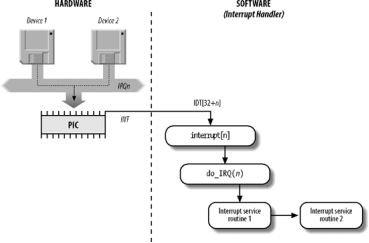
Figure 4-4. I/O interrupt handling
- The external mathematical coprocessor must be connected to the IRQ 13 line (although recent 80 × 86 processors no longer use such a device, Linux continues to support the hardy 80386 model).
- In general, an I/O device can be connected to a limited number of IRQ lines. (As a matter of fact, when playing with an old PC where IRQ sharing is not possible, you might not succeed in installing a new card because of IRQ conflicts with other already present hardware devices.)
Table 4-2. Interrupt vectors in Linux
Vector range | Use |
0–19 (0x0-0x13) | Nonmaskable interrupts and exceptions |
20–31 (0x14-0x1f) | Intel-reserved |
32–127 (0x20-0x7f) | External interrupts (IRQs) |
128 (0x80) | Programmed exception for system calls |
129–238 (0x81-0xee) | External interrupts (IRQs) |
239 (0xef) | Local APIC timer interrupt |
240 (0xf0) | Local APIC thermal interrupt (introduced in the Pentium 4 models) |
241–250 (0xf1-0xfa) | Reserved by Linux for future use |
251–253 (0xfb-0xfd) | Interprocessor interrupts |
254 (0xfe) | Local APIC error interrupt (generated when the local APIC detects an erroneous condition) |
255 (0xff) | Local APIC spurious interrupt (generated if the CPU masks an interrupt while the hardware device raises it) |
There are three ways to select a line for an IRQ-configurable device:
- By setting hardware jumpers (only on very old device cards).
- By a utility program shipped with the device and executed when installing it. Such a program may either ask the user to select an available IRQ number or probe the system to determine an available number by itself.
- By a hardware protocol executed at system startup. Peripheral devices declare which interrupt lines they are ready to use; the final values are then negotiated to reduce conflicts as much as possible. Once this is done, each interrupt handler can read the assigned IRQ by using a function that accesses some I/O ports of the device. For instance, drivers for devices that comply with the Peripheral Component Interconnect (PCI) standard use a group of functions such as pci_read_config_byte( ) to access the device configuration space.
Shows a fairly arbitrary arrangement of devices and IRQs, such as those that might be found on one particular PC.
Table 4-3. An example of IRQ assignment to I/O devices
IRQ | INT | Hardware device |
0 | 32 | Timer |
1 | 33 | Keyboard |
2 | 34 | PIC cascading |
3 | 35 | Second serial port |
4 | 36 | First serial port |
6 | 38 | Floppy disk |
8 | 40 | System clock |
10 | 42 | Network interface |
11 | 43 | USB port, sound card |
12 | 44 | PS/2 mouse |
13 | 45 | Mathematical coprocessor |
14 | 46 | EIDE disk controller’s first chain |
15 | 47 | EIDE disk controller’s second chain |
The kernel must discover which I/O device corresponds to the IRQ number before enabling interrupts. Otherwise, for example, how could the kernel handle a signal from a SCSI disk without knowing which vector corresponds to the device? The correspondence is established while initializing each device driver.
IRQ data structures
As always, when discussing complicated operations involving state transitions, it helps to understand first where key data is stored. Thus, this section explains the data structures that support interrupt handling and how they are laid out in various descriptors. Illustrates schematically the relationships between the main descriptors that represent the state of the IRQ lines. (The figure does not illustrate the data structures needed to handle softirqs and tasklets; they are discussed later in this chapter.)
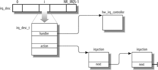
Figure 4-5. IRQ descriptors
Every interrupt vector has its own irq_desc_t descriptor,. All such descriptors are grouped together in the irq_desc array.
Table 4-4. The irq_desc_t descriptor
Field | Description |
Handler | Points to the PIC object (hw_irq_controller descriptor) that services the IRQ line. |
Handler_data | Pointer to data used by the PIC methods. |
Action | Identifies the interrupt service routines to be invoked when the IRQ occurs. The field points to the first element of the list of irqaction descriptors associated with the IRQ. The irqaction descriptor is described later in the chapter. |
Status | A set of flags describing the IRQ line status. |
Depth | Shows 0 if the IRQ line is enabled and a positive value if it has been disabled at least once. |
Irq_count | Counter of interrupt occurrences on the IRQ line (for diagnostic use only). |
Irqs_unhandled | Counter of unhandled interrupt occurrences on the IRQ line (for diagnostic use only). |
Lock | A spin lock used to serialize the accesses to the IRQ descriptor and to the |
An interrupt is unexpected if it is not handled by the kernel, that is, either if there is no ISR associated with the IRQ line, or if no ISR associated with the line recognizes the interrupt as raised by its own hardware device. Usually the kernel checks the number of unexpected interrupts received on an IRQ line, so as to disable the line in case a faulty hardware device keeps raising an interrupt over and over. Because the IRQ line can be shared among several devices, the kernel does not disable the line as soon as it detects a single unhandled interrupt. Rather, the kernel stores in the irq_count and irqs_unhandled fields of the irq_desc_t descriptor the total number of interrupts and the number of unexpected interrupts, respectively; when the 100,000th interrupt is raised, the kernel disables the line if the number of unhandled interrupts is above 99,900 (that is, if less than 101 interrupts over the last 100,000 received are expected interrupts from hardware devices sharing the line).
Table 4-5. Flags describing the IRQ line status
Flag name | Description |
IRQ_INPROGRESS | A handler for the IRQ is being executed. |
IRQ_DISABLED | The IRQ line has been deliberately disabled by a device driver. |
IRQ_PENDING | An IRQ has occurred on the line; its occurrence has been acknowledged to the PIC, but it has not yet been serviced by the kernel. |
IRQ_REPLAY | The IRQ line has been disabled but the previous IRQ occurrence has not yet been acknowledged to the PIC. |
IRQ_AUTODETECT | The kernel is using the IRQ line while performing a hardware device probe. |
IRQ_WAITING | The kernel is using the IRQ line while performing a hardware device probe; moreover, the corresponding interrupt has not been raised. |
IRQ_LEVEL | Not used on the 80 × 86 architecture. |
IRQ_MASKED | Not used. |
IRQ_PER_CPU | Not used on the 80 × 86 architecture. |
The depth field and the IRQ_DISABLED flag of the irq_desc_t descriptor specify whether the IRQ line is enabled or disabled. Every time the disable_irq( ) or disable_irq_nosync( ) function is invoked, the depth field is increased; if depth is equal to 0, the function disables the IRQ line and sets its IRQ_DISABLED flag.[*] Conversely, each invocation of the enable_irq( ) function decreases the field; if depth becomes 0, the function enables the IRQ line and clears its IRQ_DISABLED flag.
During system initialization, the init_IRQ( ) function sets the status field of each IRQ main descriptor to IRQ _DISABLED. Moreover, init_IRQ( ) updates the IDT by replacing the interrupt gates set up by setup_idt( ) with new ones. This is accomplished through the following statements:
For (i = 0; i < NR_IRQS; i++)
If (i+32 != 128)
Set_intr_gate(i+32,interrupt[i]);
This code looks in the interrupt array to find the interrupt handler addresses that it uses to set up the interrupt gates . Each entry n of the interrupt array stores the address of the interrupt handler for IRQ n. Notice that the interrupt gate corresponding to vector 128 is left untouched, because it is used for the system call’s programmed exception.
In addition to the 8259A chip that was mentioned near the beginning of this chapter, Linux supports several other PIC circuits such as the SMP IO-APIC, Intel PIIX4’s internal 8259 PIC, and SGI’s Visual Workstation Cobalt (IO-)APIC. To handle all such devices in a uniform way, Linux uses a PIC object, consisting of the PIC name and seven PIC standard methods. The advantage of this object-oriented approach is that drivers need not to be aware of the kind of PIC installed in the system. Each driver-visible interrupt source is transparently wired to the appropriate controller. The data structure that defines a PIC object is called hw_interrupt_type (also called hw_irq_controller).
For the sake of concreteness, let’s assume that our computer is a uniprocessor with two 8259A PICs, which provide 16 standard IRQs. In this case, the handler field in each of the 16 irq_desc_t descriptors points to the i8259A_irq_type variable, which describes the 8259A PIC. This variable is initialized as follows:
Struct hw_interrupt_type i8259A_irq_type = {
.typename = "XT-PIC",
.startup = startup_8259A_irq,
.shutdown = shutdown_8259A_irq,
.enable = enable_8259A_irq,
.disable = disable_8259A_irq,
.ack = mask_and_ack_8259A,
.end = end_8259A_irq,
.set_affinity = NULL
};
The first field in this structure, "XT-PIC", is the PIC name. Next come the pointers to six different functions used to program the PIC. The first two functions start up and shut down an IRQ line of the chip, respectively. But in the case of the 8259A chip, these functions coincide with the third and fourth functions, which enable and disable the line. The mask_and_ack_8259A( ) function acknowledges the IRQ received by sending the proper bytes to the 8259A I/O ports. The end_8259A_irq( ) function is invoked when the interrupt handler for the IRQ line terminates. The last set_affinity method is set to NULL: it is used in multiprocessor systems to declare the “affinity” of CPUs for specified IRQs — that is, which CPUs are enabled to handle specific IRQs.
As described earlier, multiple devices can share a single IRQ. Therefore, the kernel maintains irqaction descriptors, each of which refers to a specific hardware device and a specific interrupt. Table 4-6. Fields of the irqaction descriptor
Field name | Description |
Handler | Points to the interrupt service routine for an I/O device. This is the key field that allows many devices to share the same IRQ. |
Flags | This field includes a few fields that describe the relationships between the IRQ line and the I/O device |
Mask | Not used. |
Name | The name of the I/O device (shown when listing the serviced IRQs by reading the /proc/interrupts file). |
Dev_id | A private field for the I/O device. Typically, it identifies the I/O device itself, or it points to the device driver’s data. |
Next | Points to the next element of a list of irqaction descriptors. The elements in the list refer to hardware devices that share the same IRQ. |
Irq | IRQ line. |
Dir | Points to the descriptor of the /proc/irq/n directory associated with the IRQn. |
Table 4-7. Flags of the irqaction descriptor
Flag name | Description |
SA_INTERRUPT | The handler must execute with interrupts disabled. |
SA_SHIRQ | The device permits its IRQ line to be shared with other devices. |
SA_SAMPLE_RANDOM | The device may be considered a source of events that occurs randomly; it can thus be used by the kernel random number generator. (Users can access this feature by taking random numbers from the /dev/random and /dev/urandom device files.) |
Finally, the irq_stat array includes NR_CPUS entries, one for every possible CPU in the system. Each entry of type irq_cpustat_t includes a few counters and flags used by the kernel to keep track of what each CPU is currently doing
Table 4-8. Fields of the irq_cpustat_t structure
Field name | Description |
_ _softirq_pending | Set of flags denoting the pending softirqs |
Idle_timestamp | Time when the CPU became idle (significant only if the CPU is currently idle) |
_ _nmi_count | Number of occurrences of NMI interrupts |
Apic_timer_irqs | Number of occurrences of local APIC timer interrupts |
IRQ distribution in multiprocessor systems
Linux sticks to the Symmetric Multiprocessing model (SMP ); this means, essentially, that the kernel should not have any bias toward one CPU with respect to the others. As a consequence, the kernel tries to distribute the IRQ signals coming from the hardware devices in a round-robin fashion among all the CPUs. Therefore, all the CPUs should spend approximately the same fraction of their execution time servicing I/O interrupts.
We said that the multi-APIC system has sophisticated mechanisms to dynamically distribute the IRQ signals among the CPUs.
During system bootstrap, the booting CPU executes the setup_IO_APIC_irqs( ) function to initialize the I/O APIC chip. The 24 entries of the Interrupt Redirection Table of the chip are filled, so that all IRQ signals from the I/O hardware devices can be routed to each CPU in the system according to the “lowest priority”. During system bootstrap, moreover, all CPUs execute the setup_local_APIC( ) function, which takes care of initializing the local APICs. In particular, the task priority register (TPR) of each chip is initialized to a fixed value, meaning that the CPU is willing to handle every kind of IRQ signal, regardless of its priority. The Linux kernel never modifies this value after its initialization.
All task priority registers contain the same value, thus all CPUs always have the same priority. To break a tie, the multi-APIC system uses the values in the arbitration priority registers of local APICs, as explained earlier. Because such values are automatically changed after every interrupt, the IRQ signals are, in most cases, fairly distributed among all CPUs.[*]
In short, when a hardware device raises an IRQ signal, the multi-APIC system selects one of the CPUs and delivers the signal to the corresponding local APIC, which in turn interrupts its CPU. No other CPUs are notified of the event.
All this is magically done by the hardware, so it should be of no concern for the kernel after multi-APIC system initialization. Unfortunately, in some cases the hardware fails to distribute the interrupts among the microprocessors in a fair way (for instance, some Pentium 4-based SMP motherboards have this problem). Therefore, Linux 2.6 makes use of a special kernel thread called kirqd to correct, if necessary, the automatic assignment of IRQs to CPUs.
The kernel thread exploits a nice feature of multi-APIC systems, called the IRQ affinity of a CPU: by modifying the Interrupt Redirection Table entries of the I/O APIC, it is possible to route an interrupt signal to a specific CPU. This can be done by invoking the set_ioapic_affinity_irq( ) function, which acts on two parameters: the IRQ vector to be rerouted and a 32-bit mask denoting the CPUs that can receive the IRQ. The IRQ affinity of a given interrupt also can be changed by the system administrator by writing a new CPU bitmap mask into the /proc/irq/n/smp_affinity file (n being the interrupt vector).
The kirqd kernel thread periodically executes the do_irq_balance( ) function, which keeps track of the number of interrupt occurrences received by every CPU in the most recent time interval. If the function discovers that the IRQ load imbalance between the heaviest loaded CPU and the least loaded CPU is significantly high, then it either selects an IRQ to be “moved” from a CPU to another, or rotates all IRQs among all existing CPUs.
Multiple Kernel Mode stacks
The thread_info descriptor of each process is coupled with a Kernel Mode stack in a thread_union data structure composed by one or two page frames, according to an option selected when the kernel has been compiled. If the size of the thread_union structure is 8 KB, the Kernel Mode stack of the current process is used for every type of kernel control path: exceptions, interrupts, and deferrable functions. Conversely, if the size of the thread_union structure is 4 KB, the kernel makes use of three types of Kernel Mode stacks:
- The exception stack is used when handling exceptions (including system calls). This is the stack contained in the per-process thread_union data structure, thus the kernel makes use of a different exception stack for each process in the system.
- The hard IRQ stack is used when handling interrupts. There is one hard IRQ stack for each CPU in the system, and each stack is contained in a single page frame.
- The soft IRQ stack is used when handling deferrable functions There is one soft IRQ stack for each CPU in the system, and each stack is contained in a single page frame.
All hard IRQ stacks are contained in the hardirq_stack array, while all soft IRQ stacks are contained in the softirq_stack array. Each array element is a union of type irq_ctx that span a single page. At the bottom of this page is stored a thread_info structure, while the spare memory locations are used for the stack; remember that each stack grows towards lower addresses.; the only difference is that the thread_info structure coupled with each stack is associated with a CPU rather than a process.
The hardirq_ctx and softirq_ctx arrays allow the kernel to quickly determine the hard IRQ stack and soft IRQ stack of a given CPU, respectively: they contain pointers to the corresponding irq_ctx elements.
Saving the registers for the interrupt handler
When a CPU receives an interrupt, it starts executing the code at the address found in the corresponding gate of the IDT As with other context switches, the need to save registers leaves the kernel developer with a somewhat messy coding job, because the registers have to be saved and restored using assembly language code. However, within those operations, the processor is expected to call and return from a C function. In this section, we describe the assembly language task of handling registers; in the next, we show some of the acrobatics required in the C function that is subsequently invoked.
Saving registers is the first task of the interrupt handler. As already mentioned, the address of the interrupt handler for IRQ n is initially stored in the interrupt[n] entry and then copied into the interrupt gate included in the proper IDT entry.
The interrupt array is built through a few assembly language instructions in the arch/i386/kernel/entry.S file. The array includes NR_IRQS elements, where the NR_IRQS macro yields either the number 224 if the kernel supports a recent I/O APIC chip,[*] or the number 16 if the kernel uses the older 8259A PIC chips. The element at index n in the array stores the address of the following two assembly language instructions:
Pushl $n-256
Jmp common_interrupt
The result is to save on the stack the IRQ number associated with the interrupt minus 256. The kernel represents all IRQs through negative numbers, because it reserves positive interrupt numbers to identify system calls The same code for all interrupt handlers can then be executed while referring to this number. The common code starts at label common_interrupt and consists of the following assembly language macros and instructions:
Common_interrupt:
SAVE_ALL
Movl %esp,%eax
Call do_IRQ
Jmp ret_from_intr
The SAVE_ALL macro expands to the following fragment:
Cld
Push %es
Push %ds
Pushl %eax
Pushl %ebp
Pushl %edi
Pushl %esi
Pushl %edx
Pushl %ecx
Pushl %ebx
Movl $ _ _USER_DS,%edx
Movl %edx,%ds
Movl %edx,%es
SAVE_ALL saves all the CPU registers that may be used by the interrupt handler on the stack, except for eflags , cs, eip, ss, and esp, which are already saved automatically by the control unit. The macro then loads the selector of the user data segment into ds and es.
After saving the registers, the address of the current top stack location is saved in the eax register; then, the interrupt handler invokes the do_IRQ( ) function. When the ret instruction of do_IRQ( ) is executed (when that function terminates) control is transferred to ret_from_intr( )
The do_IRQ( ) function
The do_IRQ( ) function is invoked to execute all interrupt service routines associated with an interrupt. It is declared as follows:
_ _attribute_ _((regparm(3))) unsigned int do_IRQ(struct pt_regs *regs)
The regparm keyword instructs the function to go to the eax register to find the value of the regs argument; as seen above, eax points to the stack location containing the last register value pushed on by SAVE_ALL.
The do_IRQ( ) function executes the following actions:
- Executes the irq_enter( ) macro, which increases a counter representing the number of nested interrupt handlers. The counter is stored in the preempt_count field of the thread_info structure of the current process If the size of the thread_union structure is 4 KB, it switches to the hard IRQ stack.In particular, the function performs the following substeps:
- Executes the current_thread_info( ) function to get the address of the thread_info descriptor associated with the Kernel Mode stack addressed by the esp register Compares the address of the thread_info descriptor obtained in the previous step with the address stored in hardirq_ctx[smp_processor_id( )], that is, the address of the thread_info descriptor associated with the local CPU. If the two addresses are equal, the kernel is already using the hard IRQ stack, thus jumps to step 3. This happens when an IRQ is raised while the kernel is still handling another interrupt.
- Here the Kernel Mode stack has to be switched. Stores the pointer to the current process descriptor in the task field of the thread_info descriptor in irq_ctx union of the local CPU. This is done so that the current macro works as expected while the kernel is using the hard IRQ stack Stores the current value of the esp stack pointer register in the previous_esp field of the thread_info descriptor in the irq_ctx union of the local CPU (this field is used only when preparing the function call trace for a kernel oops).
- Loads in the esp stack register the top location of the hard IRQ stack of the local CPU (the value in hardirq_ctx[smp_processor_id( )] plus 4096); the previous value of the esp register is saved in the ebx register.
- Invokes the _ _do_IRQ( ) function passing to it the pointer regs and the IRQ number obtained from the regs->orig_eax field (see the following section).
- If the hard IRQ stack has been effectively switched in step 2e above, the function copies the original stack pointer from the ebx register into the esp register, thus switching back to the exception stack or soft IRQ stack that were in use before.
- Executes the irq_exit( ) macro, which decreases the interrupt counter and checks whether deferrable kernel functions are waiting to be executed
- Terminates: the control is transferred to the ret_from_intr( ) function The _ _do_IRQ( ) function
The _ _do_IRQ( ) function receives as its parameters an IRQ number (through the eax register) and a pointer to the pt_regs structure where the User Mode register values have been saved (through the edx register).
The function is equivalent to the following code fragment:
Spin_lock(&(irq_desc[irq].lock));
Irq_desc[irq].handler->ack(irq);
Irq_desc[irq].status &= ~(IRQ_REPLAY | IRQ_WAITING);
Irq_desc[irq].status |= IRQ_PENDING;
If (!(irq_desc[irq].status & (IRQ_DISABLED | IRQ_INPROGRESS))
&& irq_desc[irq].action) {
Irq_desc[irq].status |= IRQ_INPROGRESS;
Do {
Irq_desc[irq].status &= ~IRQ_PENDING;
Spin_unlock(&(irq_desc[irq].lock));
Handle_IRQ_event(irq, regs, irq_desc[irq].action);
Spin_lock(&(irq_desc[irq].lock));
} while (irq_desc[irq].status & IRQ_PENDING);
Irq_desc[irq].status &= ~IRQ_INPROGRESS;
}
Irq_desc[irq].handler->end(irq);
Spin_unlock(&(irq_desc[irq].lock));
Before accessing the main IRQ descriptor, the kernel acquires the corresponding spin lock. The spin lock protects against concurrent accesses by different CPUs. This spin lock is necessary in a multiprocessor system, because other interrupts of the same kind may be raised, and other CPUs might take care of the new interrupt occurrences. Without the spin lock, the main IRQ descriptor would be accessed concurrently by several CPUs. As we’ll see, this situation must be absolutely avoided.
After acquiring the spin lock, the function invokes the ack method of the main IRQ descriptor. When using the old 8259A PIC, the corresponding mask_and_ack_8259A( ) function acknowledges the interrupt on the PIC and also disables the IRQ line. Masking the IRQ line ensures that the CPU does not accept further occurrences of this type of interrupt until the handler terminates. Remember that the _ _do_IRQ( ) function runs with local interrupts disabled; in fact, the CPU control unit automatically clears the IF flag of the eflags register because the interrupt handler is invoked through an IDT’s interrupt gate. However, we’ll see shortly that the kernel might re-enable local interrupts before executing the interrupt service routines of this interrupt.
When using the I/O APIC, however, things are much more complicated. Depending on the type of interrupt, acknowledging the interrupt could either be done by the ack method or delayed until the interrupt handler terminates (that is, acknowledgement could be done by the end method). In either case, we can take for granted that the local APIC doesn’t accept further interrupts of this type until the handler terminates, although further occurrences of this type of interrupt may be accepted by other CPUs.
The _ _do_IRQ( ) function then initializes a few flags of the main IRQ descriptor. It sets the IRQ_PENDING flag because the interrupt has been acknowledged (well, sort of), but not yet really serviced; it also clears the IRQ_WAITING and IRQ_REPLAY flags (but we don’t have to care about them now).
Now _ _do_IRQ( ) checks whether it must really handle the interrupt. There are three cases in which nothing has to be done. These are discussed in the following list.
IRQ_DISABLED is set
A CPU might execute the _ _do_IRQ( ) function even if the corresponding IRQ line is disabled; you’ll find an explanation for this nonintuitive case Moreover, buggy motherboards may generate spurious interrupts even when the IRQ line is disabled in the PIC.
IRQ_INPROGRESS is set
In a multiprocessor system, another CPU might be handling a previous occurrence of the same interrupt. Why not defer the handling of this occurrence to that CPU? This is exactly what is done by Linux. This leads to a simpler kernel architecture because device drivers’ interrupt service routines need not to be reentrant (their execution is serialized). Moreover, the freed CPU can quickly return to what it was doing, without dirtying its hardware cache; this is beneficial to system performance. The IRQ_INPROGRESS flag is set whenever a CPU is committed to execute the interrupt service routines of the interrupt; therefore, the _ _do_IRQ( ) function checks it before starting the real work.
Irq_desc[irq].action is NULL
This case occurs when there is no interrupt service routine associated with the interrupt. Normally, this happens only when the kernel is probing a hardware device.
Let’s suppose that none of the three cases holds, so the interrupt has to be serviced. The _ _do_IRQ( ) function sets the IRQ_INPROGRESS flag and starts a loop. In each iteration, the function clears the IRQ_PENDING flag, releases the interrupt spin lock, and executes the interrupt service routines by invoking handle_IRQ_event( ) (described later in the chapter). When the latter function terminates, _ _do_IRQ( ) acquires the spin lock again and checks the value of the IRQ_PENDING flag. If it is clear, no further occurrence of the interrupt has been delivered to another CPU, so the loop ends. Conversely, if IRQ_PENDING is set, another CPU has executed the do_IRQ( ) function for this type of interrupt while this CPU was executing handle_IRQ_event( ). Therefore, do_IRQ( ) performs another iteration of the loop, servicing the new occurrence of the interrupt.[*]
Our _ _do_IRQ( ) function is now going to terminate, either because it has already executed the interrupt service routines or because it had nothing to do. The function invokes the end method of the main IRQ descriptor. When using the old 8259A PIC, the corresponding end_8259A_irq( ) function reenables the IRQ line (unless the interrupt occurrence was spurious). When using the I/O APIC, the end method acknowledges the interrupt (if not already done by the ack method).
Finally, _ _do_IRQ( ) releases the spin lock: the hard work is finished!
Reviving a lost interrupt
The _ _do_IRQ( ) function is small and simple, yet it works properly in most cases. Indeed, the IRQ_PENDING, IRQ_INPROGRESS, and IRQ_DISABLED flags ensure that interrupts are correctly handled even when the hardware is misbehaving. However, things may not work so smoothly in a multiprocessor system.
Suppose that a CPU has an IRQ line enabled. A hardware device raises the IRQ line, and the multi-APIC system selects our CPU for handling the interrupt. Before the CPU acknowledges the interrupt, the IRQ line is masked out by another CPU; as a consequence, the IRQ_DISABLED flag is set. Right afterwards, our CPU starts handling the pending interrupt; therefore, the do_IRQ( ) function acknowledges the interrupt and then returns without executing the interrupt service routines because it finds the IRQ_DISABLED flag set. Therefore, even though the interrupt occurred before the IRQ line was disabled, it gets lost.
To cope with this scenario, the enable_irq( ) function, which is used by the kernel to enable an IRQ line, checks first whether an interrupt has been lost. If so, the function forces the hardware to generate a new occurrence of the lost interrupt:
Spin_lock_irqsave(&(irq_desc[irq].lock), flags);
If (--irq_desc[irq].depth == 0) {
Irq_desc[irq].status &= ~IRQ_DISABLED;
If (irq_desc[irq].status & (IRQ_PENDING | IRQ_REPLAY))
== IRQ_PENDING) {
Irq_desc[irq].status |= IRQ_REPLAY;
Hw_resend_irq(irq_desc[irq].handler,irq);
}
Irq_desc[irq].handler->enable(irq);
}
Spin_lock_irqrestore(&(irq_desc[irq].lock), flags);
The function detects that an interrupt was lost by checking the value of the IRQ_PENDING flag. The flag is always cleared when leaving the interrupt handler; therefore, if the IRQ line is disabled and the flag is set, then an interrupt occurrence has been acknowledged but not yet serviced. In this case the hw_resend_irq( ) function raises a new interrupt. This is obtained by forcing the local APIC to generate a self-. The role of the IRQ_REPLAY flag is to ensure that exactly one self-interrupt is generated. Remember that the _ _do_IRQ( ) function clears that flag when it starts handling the interrupt.
Interrupt service routines
As mentioned previously, an interrupt service routine handles an interrupt by executing an operation specific to one type of device. When an interrupt handler must execute the ISRs, it invokes the handle_IRQ_event( ) function. This function essentially performs the following steps:
- Enables the local interrupts with the sti assembly language instruction if the SA_INTERRUPT flag is clear.
- Executes each interrupt service routine of the interrupt through the following code:
- Retval = 0;
- Do {
- Retval |= action->handler(irq, action->dev_id, regs);
- Action = action->next;
} while (action);
At the start of the loop, action points to the start of a list of irqaction data structures that indicate the actions to be taken upon receiving the interrupt Disables local interrupts with the cli assembly language instruction.
7. Terminates by returning the value of the retval local variable, that is, 0 if no interrupt service routine has recognized interrupt, 1 otherwise (see next).
All interrupt service routines act on the same parameters (once again they are passed through the eax, edx, and ecx registers, respectively):
Irq
The IRQ number
Dev_id
The device identifier
Regs
A pointer to a pt_regs structure on the Kernel Mode (exception) stack containing the registers saved right after the interrupt occurred. The pt_regs structure consists of 15 fields:
- The first nine fields are the register values pushed by SAVE_ALL
- The tenth field, referenced through a field called orig_eax, encodes the IRQ number
- The remaining fields correspond to the register values pushed on automatically by the control unit
The first parameter allows a single ISR to handle several IRQ lines, the second one allows a single ISR to take care of several devices of the same type, and the last one allows the ISR to access the execution context of the interrupted kernel control path. In practice, most ISRs do not use these parameters.
Every interrupt service routine returns the value 1 if the interrupt has been effectively handled, that is, if the signal was raised by the hardware device handled by the interrupt service routine (and not by another device sharing the same IRQ); it returns the value 0 otherwise.
The SA_INTERRUPT flag of the main IRQ descriptor determines whether interrupts must be enabled or disabled when the do_IRQ( ) function invokes an ISR. An ISR that has been invoked with the interrupts in one state is allowed to put them in the opposite state. In a uniprocessor system, this can be achieved by means of the cli (disable interrupts) and sti (enable interrupts) assembly language instructions.
The structure of an ISR depends on the characteristics of the device handled.
Dynamic allocation of IRQ lines
A few vectors are reserved for specific devices, while the remaining ones are dynamically handled. There is, therefore, a way in which the same IRQ line can be used by several hardware devices even if they do not allow IRQ sharing. The trick is to serialize the activation of the hardware devices so that just one owns the IRQ line at a time.
Before activating a device that is going to use an IRQ line, the corresponding driver invokes request_irq( ). This function creates a new irqaction descriptor and initializes it with the parameter values; it then invokes the setup_irq( ) function to insert the descriptor in the proper IRQ list. The device driver aborts the operation if setup_irq( ) returns an error code, which usually means that the IRQ line is already in use by another device that does not allow interrupt sharing. When the device operation is concluded, the driver invokes the free_irq( ) function to remove the descriptor from the IRQ list and release the memory area.
Let’s see how this scheme works on a simple example. Assume a program wants to address the /dev/fd0 device file, which corresponds to the first floppy disk on the system.[*] The program can do this either by directly accessing /dev/fd0 or by mounting a filesystem on it. Floppy disk controllers are usually assigned IRQ 6; given this, a floppy driver may issue the following request:
Request_irq(6, floppy_interrupt,
SA_INTERRUPT|SA_SAMPLE_RANDOM, "floppy", NULL);
As can be observed, the floppy_interrupt( ) interrupt service routine must execute with the interrupts disabled (SA_INTERRUPT flag set) and no sharing of the IRQ (SA_SHIRQ flag missing). The SA_SAMPLE_RANDOM flag set means that accesses to the floppy disk are a good source of random events to be used for the kernel random number generator. When the operation on the floppy disk is concluded (either the I/O operation on /dev/fd0 terminates or the filesystem is unmounted), the driver releases IRQ 6:
Free_irq(6, NULL);
To insert an irqaction descriptor in the proper list, the kernel invokes the setup_irq( ) function, passing to it the parameters irq _nr, the IRQ number, and new (the address of a previously allocated irqaction descriptor). This function:
- Checks whether another device is already using the irq _nr IRQ and, if so, whether the SA_SHIRQ flags in the irqaction descriptors of both devices specify that the IRQ line can be shared. Returns an error code if the IRQ line cannot be used.
- Adds *new (the new irqaction descriptor pointed to by new) at the end of the list to which irq _desc[irq _nr]->action points.
- If no other device is sharing the same IRQ, the function clears the IRQ _DISABLED, IRQ_AUTODETECT, IRQ_WAITING, and IRQ _INPROGRESS flags in the flags field of *new and invokes the startup method of the irq_desc[irq_nr]->handler PIC object to make sure that IRQ signals are enabled.
Here is an example of how setup_irq( ) is used, drawn from system initialization. The kernel initializes the irq0 descriptor of the interval timer device by executing the following instructions in the time_init( ) function
Struct irqaction irq0 =
{timer_interrupt, SA_INTERRUPT, 0, "timer", NULL, NULL};
Setup_irq(0, &irq0);
First, the irq0 variable of type irqaction is initialized: the handler field is set to the address of the timer_interrupt( ) function, the flags field is set to SA_INTERRUPT, the name field is set to "timer", and the fifth field is set to NULL to show that no dev_id value is used. Next, the kernel invokes setup_irq( ) to insert irq0 in the list of irqaction descriptors associated with IRQ 0.
Interprocessor Interrupt Handling
Interprocessor interrupts allow a CPU to send interrupt signals to any other CPU in the system. As explained in the section an interprocessor interrupt (IPI) is delivered not through an IRQ line, but directly as a message on the bus that connects the local APIC of all CPUs (either a dedicated bus in older motherboards, or the system bus in the Pentium 4-based motherboards).
On multiprocessor systems, Linux makes use of three kinds of interprocessor interrupts
CALL_FUNCTION_VECTOR (vector 0xfb)
Sent to all CPUs but the sender, forcing those CPUs to run a function passed by the sender. The corresponding interrupt handler is named call_function_interrupt( ). The function (whose address is passed in the call_data global variable) may, for instance, force all other CPUs to stop, or may force them to set the contents of the Memory Type Range Registers (MTRRs).[*] Usually this interrupt is sent to all CPUs except the CPU executing the calling function by means of the smp_call_function( ) facility function.
RESCHEDULE_VECTOR (vector 0xfc)
When a CPU receives this type of interrupt, the corresponding handler — named reschedule_interrupt( ) — limits itself to acknowledging the interrupt. Rescheduling is done automatically when returning from the interrupt
INVALIDATE_TLB_VECTOR (vector 0xfd)
Sent to all CPUs but the sender, forcing them to invalidate their Translation Lookaside Buffers. The corresponding handler, named invalidate_interrupt( ), flushes some TLB entries of the processor as described in the section .The assembly language code of the interprocessor interrupt handlers is generated by the BUILD_INTERRUPT macro: it saves the registers, pushes the vector number minus 256 on the stack, and then invokes a high-level C function having the same name as the low-level handler preceded by smp_. For instance, the high-level handler of the CALL_FUNCTION_VECTOR interprocessor interrupt that is invoked by the low-level call_function_interrupt( ) handler is named smp_call_function_interrupt( ). Each high-level handler acknowledges the interprocessor interrupt on the local APIC and then performs the specific action triggered by the interrupt.
Thanks to the following group of functions, issuing interprocessor interrupts (IPIs) becomes an easy task:
Send_IPI_all( )
Sends an IPI to all CPUs (including the sender)
Send_IPI_allbutself( )
Sends an IPI to all CPUs except the sender
Send_IPI_self( )
Sends an IPI to the sender CPU
Send_IPI_mask( )
Sends an IPI to a group of CPUs specified by a bit mask
Basic concepts
An instruction has a number of stages. The various stages can be worked on simultaneously through various blocks of production. This is a pipeline. This process is also referred as instruction pipeline. Figure 8.1 shown the pipeline of two independent stages: fetch instruction and execution instruction. The first stage fetches an instruction and buffers it. While the second stage is executing the instruction, the first stage takes advantage of any unused memory cycles to fetch and buffer the next instruction. This process will speed up instruction execution

Figure 8.1. Two stages Instruction Pipeline
Pipeline principle
The decomposition of the instruction processing by 6 stages is the following.
- Fetch Instruction (FI): Read the next expected introduction into a buffer
- Decode Instruction (DI): Determine the opcode and the operand specifiers
- Calculate Operands (CO): Calculate the effective address of each source operand. This may involve displacement, register indirect, indirect or other forms of address calculations.
- Fetch Operands (FO): Fetch each operand from memory. Operands in register need not be fetched.
- Execute Instruction (EI): Perform the indicated operation and store the result, if any, in the specified destination operand location.
- Write Operand (WO): Store result in memory.
Using the assumption of the equal duration for various stages, the figure 8.2 shown that a six stage pipeline can reduce the execution time for 9 instructions from 54 time units to 14 time units.
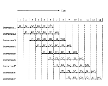
Figure 8.2. Timing diagram for instruction pipeline operation.
Also the diagram assumes that all of the stages can be performed in parallel, in particular, it is assumed that there are no memory conflicts. The processor make use of instruction pipelining to speed up executions, pipeling invokes breaking up the instruction cycle into a number of separate stages in a sequence. However the occurrence of branches and independencies between instruction complates the design and use of pipeline.
2. Pipeline Performance and Limitations
With the pipeling approach, as a form of parallelism, a “good” design goal of any system is to have all of its components performing useful work all of the time, we can obtain a high efficiency. The instruction cycle state diagram clearly shows the sequence of operations that take place in order to execute a single instruction.
This strategy can give the following:
- Perform all tasks concurrently, but on different sequential instructions
– The result is temporal parallelism.
– Result is the instruction pipeline.
Pipeline performance
In this subsection, we can show some measures of pipeline performance based on the book “Computer Organization and Architecture: Designing for Performance”, 6th Edition by William Stalling.
The cycle time of an instruction pipeline can be determined as:
T=max[Ti]+d=Tm+d
With 1 i
k
Where:
Tm
= Maximun stage delay through stage
k = number of stages in instruction pipeline
d = time delay of a latch.
In general, the time delay d is equivalent to a clock pulse and Tm
>> d. Suppose that n instruction are processed with no branched.
- The total time required Tk
- To execute all n instruction is:
Tk
= [k + (n-1)]
- The speedup factor for the instruction pipeline compared to execution without the pipeline is defined as:
SK=T1TK=nkτ[k+(n−1)]τ=nkk+(n−1)
- An ideal pipeline divides a task into k independent sequential subtasks
– Each subtask requires 1 time unit to complete
– The task itself then requires k time units tocomplete. For n iterations of the task, the execution times will be:
– With no pipelining: nk time units
– With pipelining: k + (n-1) time units
Speedup of a k-stage pipeline is thus
S = nk / [k+(n-1)] ==> k (for large n)
Pipeline Limitations
Several factors serve to limit the pipeline performance. If the six stage are not of equal duration, there will be some waiting involved at various pipeline stage. Another difficulty is the condition branch instruction or the unpredictable event is an interrupt. Other problem arise that the memory conflicts could occur. So the system must contain logic to account for the type of conflict.
- Pipeline depth
- Data dependencies also factor into the effective length of pipelines
- Logic to handle memory and register use and to control the overall pipeline increases significantly with increasing pipeline depth
– If the speedup is based on the number of stages, why not build lots of stages?
– Each stage uses latches at its input (output) to buffer the next set of inputs
+ If the stage granularity is reduced too much, the latches and their control become a significant hardware overhead
+ Also suffer a time overhead in the propagation time through the latches
- Limits the rate at which data can be clocked through the pipeline
- Data dependencies
– Pipelining must insure that computed results are the same as if computation was performed in strict sequential order
– With multiple stages, two instructions “in execution” in the pipeline may have data dependencies. So we must design the pipeline to prevent this.
– Data dependency examples:
A = B + C
D = E + A
C = G x H
A = D / H
Data dependencies limit when an instruction can be input to the pipeline.
- Branching
One of the major problems in designing an instruction pipeline is assuring a steady flow of instructions to initial stages of the pipeline. However, 15-20% of instructions in an assembly-level stream are (conditional) branches. Of these, 60-70% take the branch to a target address. Until the instruction is actually executed, it is impossible to determin whether the branch will be taken or not.
- Impact of the branch is that pipeline never really operates at its full capacity.
– The average time to complete a pipelined instruction becomes
Tave =(1-pb)1 + pb[pt(1+b) + (1-pt)1]
– A number of techniques can be used to minimize the impact of the branch instruction (the branch penalty).
- A several approaches have been taken for dealing with conditional branches:
+ Multiple streams
+ Prefetch branch target
+ Loop buffer
+ Branch prediction
+Delayed branch.
- Multiple streams
- Replicate the initial portions of the pipeline and fetch both possible next instructions
- Increases chance of memory contention
- Must support multiple streams for each instruction in the pipeline
- Prefetch branch target
- When the branch instruction is decoded, begin to fetch the branch target instruction and place in a second prefetch buffer
- If the branch is not taken, the sequential instructions are already in the pipe, so there is not loss of performance
- If the branch is taken, the next instruction has been prefetched and results in minimal branch penalty (don’t have to incur a memory read operation at the end of the branch to fetch the instruction)
- Loop buffer: Look ahead, look behind buffer
- Many conditional branches operations are used for loop control
- Expand prefetch buffer so as to buffer the last few instructions executed in addition to the ones that are waiting to be executed
- If buffer is big enough, entire loop can be held in it, this can reduce the branch penalty.
- Branch prediction
- Make a good guess as to which instruction will be executed next and start that one down the pipeline.
- Static guesses: make the guess without considering the runtime history of the program
Branch never taken
Branch always taken
Predict based on the opcode
- Dynamic guesses: track the history of conditional branches in the program.
Taken / not taken switch History table
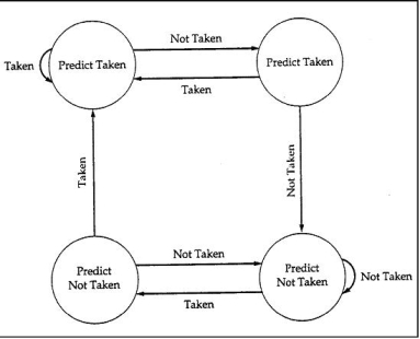
Figure 8.3. Branch prediction using 2 history bits
- Delayed branch
- Minimize the branch penalty by finding valid instructions to execute in the pipeline while the branch address is being resolved.
- It is possible to improve performance by automatically rearranging instruction within a program, so that branch instruction occur later than actually desired
- Compiler is tasked with reordering the instruction sequence to find enough independent instructions (wrt to the conditional branch) to feed into the pipeline after the branch that the branch penalty is reduced to zero
3. Superscalar and Super pipelined Processors
Super pipeline designs
– Observation: a large number of operations do not require the full clock cycle to complete
– High performance can be obtained by subdividing the clock cycle into a number of sub intervals » Higher clock frequency!
– Subdivide the “macro” pipeline H/W stages into smaller (thus faster) substages and clock data through at the higher clock rate
– Time to complete individual instructions does not change
» Degree of parallelism goes up
» Perceived speedup goes up
Superscalar
– Implement the CPU such that more than one instruction can be performed (completed) at a time
– Involves replication of some or all parts of the CPU/ALU
– Examples:
» Fetch multiple instructions at the same time
» Decode multiple instructions at the same time
» Perform add and multiply at the same time
» Perform load/stores while performing ALU operation
– Degree of parallelism and hence the speedup of the machine goes up as more instructions are executed in parallel
- Data dependencies in superscalar
– It must insure computed results are the same as would be computed on a strictly sequential machine
– Two instructions can not be executed in parallel if the (data) output of one is the input of the other or if they both write to the same output location
– Consider:
S1: A = B + C
S2: D = A + 1
S3: B = E + F
S4: A = E + 3
Resource dependencies:
– In the above sequence of instructions, the adder unit gets a real workout!
– Parallelism is limited by the number of adders in the ALU
Instruction issue policy
Problem: In what order are instructions issued to the execution unit and in what order do they finish?
There is 3 types of ordering.
- The order in which instructions are fetched
- The order in which instructions are executed
- The order in which instructions update the contents of registre or memory location.
- In-order issue, in-order completion
» Simplest method, but severely limits performance
» Strict ordering of instructions: data and procedural dependencies or resource conflicts delay all subsequent instructions
» Delay execution of some instructions delay all subsequent instructions
- In-order issue, out-of-order completion
» Any number of instructions can be executed at a time
» Instruction issue is still limited by resource conflicts or data and procedural dependencies
» Output dependencies resulting from out-of order completion must be resolved
» “Instruction” interrupts can be tricky
- Out-of-order issue, out-of-order completion
» Decode and execute stages are decoupled via an instruction buffer “window”
» Decoded instructions are “stored” in the window awaiting execution
» Functional units will take instructions from the window in an attempt to stay busy
This can result in out-of-order execution
S1: A = B + C
S2: D = E + 1
S3: G = E + F
S4: H = E * 3
“Ant dependence” class of data dependencies must be dealt with it.
Parallel computing is a computing where the jobs are broken into discrete parts that can be executed concurrently. Each part is further broken down to a series of instructions. Instructions from each part execute simultaneously on different CPUs. Parallel systems deal with the simultaneous use of multiple computer resources that can include a single computer with multiple processors, a number of computers connected by a network to form a parallel processing cluster or a combination of both.
Parallel systems are more difficult to program than computers with a single processor because the architecture of parallel computers varies accordingly and the processes of multiple CPUs must be coordinated and synchronized.
The crux of parallel processing are CPUs. Based on the number of instruction and data streams that can be processed simultaneously, computing systems are classified into four major categories:
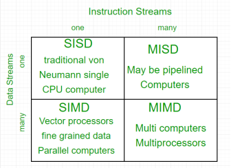
Flynn’s classification –
- Single-instruction, single-data (SISD) systems –
An SISD computing system is a uniprocessor machine which is capable of executing a single instruction, operating on a single data stream. In SISD, machine instructions are processed in a sequential manner and computers adopting this model are popularly called sequential computers. Most conventional computers have SISD architecture. All the instructions and data to be processed have to be stored in primary memory.
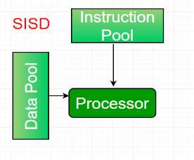
The speed of the processing element in the SISD model is limited(dependent) by the rate at which the computer can transfer information internally. Dominant representative SISD systems are IBM PC, workstations.
2. Single-instruction, multiple-data (SIMD) systems –
An SIMD system is a multiprocessor machine capable of executing the same instruction on all the CPUs but operating on different data streams. Machines based on an SIMD model are well suited to scientific computing since they involve lots of vector and matrix operations. So that the information can be passed to all the processing elements (PEs) organized data elements of vectors can be divided into multiple sets(N-sets for N PE systems) and each PE can process one data set.
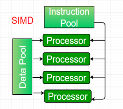
Dominant representative SIMD systems is Cray’s vector processing machine.
3. Multiple-instruction, single-data (MISD) systems –
An MISD computing system is a multiprocessor machine capable of executing different instructions on different PEs but all of them operating on the same dataset .
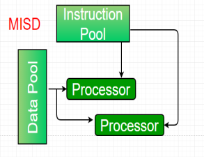
Example Z = sin(x)+cos(x)+tan(x)
The system performs different operations on the same data set. Machines built using the MISD model are not useful in most of the application, a few machines are built, but none of them are available commercially.
4. Multiple-instruction, multiple-data (MIMD) systems –
An MIMD system is a multiprocessor machine which is capable of executing multiple instructions on multiple data sets. Each PE in the MIMD model has separate instruction and data streams; therefore machines built using this model are capable to any kind of application. Unlike SIMD and MISD machines, PEs in MIMD machines work asynchronously.
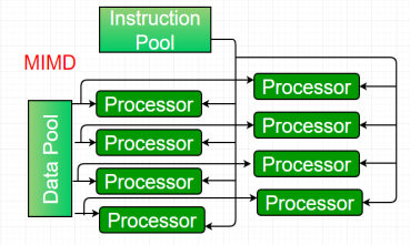
MIMD machines are broadly categorized into shared-memory MIMD and distributed-memory MIMD based on the way PEs are coupled to the main memory.
In the shared memory MIMD model (tightly coupled multiprocessor systems), all the PEs are connected to a single global memory and they all have access to it. The communication between PEs in this model takes place through the shared memory, modification of the data stored in the global memory by one PE is visible to all other PEs. Dominant representative shared memory MIMD systems are Silicon Graphics machines and Sun/IBM’s SMP (Symmetric Multi-Processing).
In Distributed memory MIMD machines (loosely coupled multiprocessor systems) all PEs have a local memory. The communication between PEs in this model takes place through the interconnection network (the inter process communication channel, or IPC). The network connecting PEs can be configured to tree, mesh or in accordance with the requirement.
The shared-memory MIMD architecture is easier to program but is less tolerant to failures and harder to extend with respect to the distributed memory MIMD model. Failures in a shared-memory MIMD affect the entire system, whereas this is not the case of the distributed model, in which each of the PEs can be easily isolated. Moreover, shared memory MIMD architectures are less likely to scale because the addition of more PEs leads to memory contention. This is a situation that does not happen in the case of distributed memory, in which each PE has its own memory. As a result of practical outcomes and user’s requirement , distributed memory MIMD architecture is superior to the other existing models.
Definitions
A multi core processor is a single integrated circuit (a.k.a., chip multiprocessor or CMP) that contains multiple core processing units, more commonly known as cores. There are many different multicore processor architectures, which vary in terms of
- Number of cores. Different multicore processors often have different numbers of cores. For example, a quad-core processor has four cores. The number of cores is usually a power of two.
- Number of core types. •
- Homogeneous (symmetric) cores.All of the cores in a homogeneous multicore processor are of the same type; typically the core processing units are general-purpose central processing units that run a single multicore operating system.
- Heterogeneous (asymmetric) cores. Heterogeneous multicore processors have a mix of core types that often run different operating systems and include graphics processing units.
- Number and level of caches. Multicore processors vary in terms of theirinstruction and data caches, which are relatively small and fast pools of local memory.
- How cores are interconnected. Multicore processors also vary in terms of their bus architectures.
- Isolation. The amount, typically minimal, of in-chip support for the spatial and temporal isolation of cores:
- Physical isolation ensures that different cores cannot access the same physical hardware (e.g., memory locations such as caches and RAM).
- Temporal isolation ensures that the execution of software on one core does not impact the temporal behavior of software running on another core.
Homogeneous Multicore Processor
The following figure notionally shows the architecture of a system in which 14 software applications are allocated by a single host operating system to the cores in a homogeneous quad-core processor. In this architecture, there are three levels of cache, which are progressively larger but slower: L1 (consisting of an instruction cache and a data cache), L2, and L3. Note that the L1 and L2 caches are local to a single core, whereas L3 is shared among all four cores.
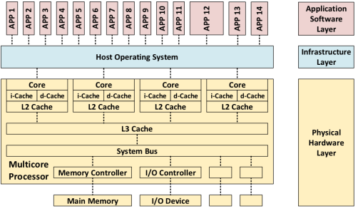
Heterogeneous Multicore Processor
The following figure notionally shows how these 14 applications could be allocated to four different operating systems, which in turn are allocated to four different cores, in a heterogeneous, quad-core processor. From left to right, the cores include a general-purpose central processing unit core running Windows; 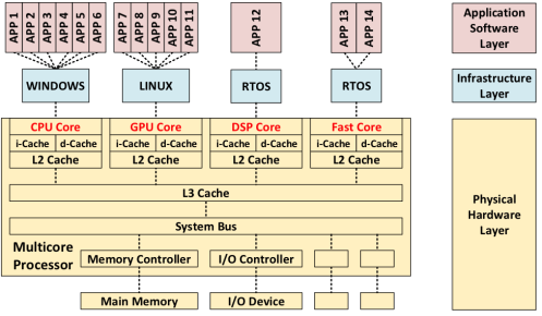
Current Trends in Multicore Processing
Multicore processors are replacing traditional, single-core processors so that fewer single-core processors are being produced and supported. Consequently, single-core processors are becoming technologically obsolete, such as computer-on-a-chip processors, are becoming more common.
Although multicore processors have largely saturated some application domains (e.g., cloud computing, data warehousing, and on-line shopping), they are just starting to be used in real-time, safety- and security-critical, cyber-physical systems. One area in which multicore processing is becoming popular is in environments constrained by size, weight, and power, and cooling in which significantly increased performance is required.
Pros of Multicore Processing
Multicore processing is typically commonplace because it offers advantages in the following seven areas:
- Energy Efficiency. By using multicore processors, architects can decrease the number of embedded computers. They overcome increased heat generation due to moores law (i.e., smaller circuits increase electrical resistance, which creates more heat), which in turn decreases the need for cooling. The use of multicore processing reduces power consumption (less energy wasted as heat), which increases battery life.
- True Concurrency. By allocating applications to different cores, multicore processing increases the intrinsic support for actual (as opposed to virtual) parallel processing within individual software applications across multiple applications.
- Performance. Multicore processing can increase performance by running multiple applications concurrently. The decreased distance between cores on an integrated chip enables shorter resource access latency and higher cache speeds when compared to using separate processors or computers. However, the size of the performance increase depends on the number of cores, the level of real concurrency in the actual software, and the use of shared resources.
- Isolation. Multicore processors may improve (but do not guarantee) spatial and temporal isolation (segregation) compared to single-core architectures. Software running on one core is less likely to affect software on another core than if both are executing on the same single core. This decoupling is due to both spatial isolation (of data in core-specific cashes) and temporal isolation, because threads on one core are not delayed by threads on another core. Multicore processing may also improve robustness by localizing the impact of defects to single core. This increased isolation is particularly important in the independent execution of mixed criticality applications (mission-critical, safety critical, and security-critical).
- Reliability and Robustness. Allocating software to multiple cores increases reliability and robustness (i.e., fault and failure tolerance) by limiting fault and/or failure propagation from software on one core to software on another. The allocation of software to multiple cores also supports failure tolerance by supporting failover from one core to another (and subsequent recovery).
- Obsolescence Avoidance. The use of multicore processors enables architects to avoid technological obsolescence and improve maintainability. Chip manufacturers are applying the latest technical advances to their multicore chips. As the number of cores continues to increase, it becomes increasingly hard to obtain single-core chips.
- Hardware Costs. By using multicore processors, architects can produce systems with fewer computers and processors.
Cons of Multicore Processing
Although there are many advantages to moving to multicore processors, architects must address disadvantages and associated risks in the following six areas:
- Shared Resources. Cores on the same processor share both processor-internal resources (L3 cache, system bus, memory controller, I/O controllers, and interconnects) and processor-external resources (main memory, I/O devices, and networks). These shared resources imply (1) the existence of single points of failure, (2) two applications running on the same core can interfere with each other, and (3) software running on one core can impact software running on another core (i.e., interference can violate spatial and temporal isolation because multicore support for isolation is limited). The diagram below uses the color red to illustrate six shared resources.
- Interference. Interference occurs when software executing on one core impacts the behavior of software executing on other cores in the same processor. This interference includes failures of both spatial isolation (due to shared memory access) and failure of temporal isolation (due to interference delays and/or penalties). Temporal isolation is a bigger problem than spatial isolation since multicore processors may have special hardware that can be used to enforce spatial isolation (to prevent software running on different cores from accessing the same processor-internal memory). The number of interference paths increases rapidly with the number of cores and the exhaustive analysis of all interference paths is often impossible. The impracticality of exhaustive analysis necessitates the selection of representative interference paths when analyzing isolation. The following diagram uses the color red to illustrate three possible interference paths between pairs of applications involving six shared resources.
- Concurrency Defects. Cores execute concurrently, creating the potential for concurrency defects including deadlock, livelock, starvation, suspension, (data) race conditions, priority inversion, order violations, and atomicity violations. Note that these are essentially the same types of concurrency defects that can occur when software is allocated to multiple threads on a single core.
- Non-determinism. Multicore processing increases non-determinism. For example, I/O Interrupts have top-level hardware priority (also a problem with single core processors). Multicore processing is also subject to lock trashing, which stems from excessive lock conflicts due to simultaneous access of kernel services by different cores (resulting in decreased concurrency and performance). The resulting non-deterministic behavior can be unpredictable, can cause related faults and failures, and can make testing more difficult (e.g., running the same test multiple times may not yield the same test result).
- Analysis Difficulty. The real concurrency due to multicore processing requires different memory consistency models than virtual interleaved concurrency. It also breaks traditional analysis approaches for work on single core processors. The analysis of maximum time limits is harder and may be overly conservative. Although interference analysis becomes more complex as the number of cores-per-processor increases, overly-restricting the core number may not provide adequate performance.
- Accreditation and Certification. Interference between cores can cause missed deadlines and excessive jitter, which in turn can cause faults (hazards) and failures (accidents). Verifying a multicore system requires proper real-time scheduling and timing analysis and/or specialized performance testing. Moving from a single-core to a multicore architecture may require recertification. Unfortunately, current safety policy guidelines are based on single-core architectures and must be updated based on the recommendations that will be listed in the final blog entry in this series.
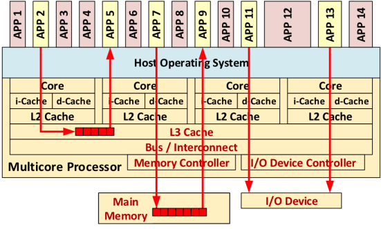
SEI-Research on Multicore Processing
Real-time scheduling on multicore processing platforms is a Department of Defense (DoD) technical area of urgent and other systems that demand ever-increasing computational power.. We developed a mode-change protocol for multicores with several operational modes, such as aircraft taxi, takeoff, flight, and landing modes. The SEI developed the first protocol to allow multicore software to switch modes while meeting all timing requirements, thereby allowing software designers add or remove software functions while ensuring safety.
Parallel computing is a computing where the jobs are broken into discrete parts that can be executed concurrently. Each part is further broken down to a series of instructions. Instructions from each part execute simultaneously on different CPUs. Parallel systems deal with the simultaneous use of multiple computer resources that can include a single computer with multiple processors, a number of computers connected by a network to form a parallel processing cluster or a combination of both.
Parallel systems are more difficult to program than computers with a single processor because the architecture of parallel computers varies accordingly and the processes of multiple CPUs must be coordinated and synchronized.
The crux of parallel processing are CPUs. Based on the number of instruction and data streams that can be processed simultaneously, computing systems are classified into four major categories:
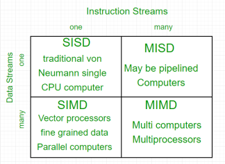
Flynn’s classification –
- Single-instruction, single-data (SISD) systems –
An SISD computing system is a uniprocessor machine which is capable of executing a single instruction, operating on a single data stream. In SISD, machine instructions are processed in a sequential manner and computers adopting this model are popularly called sequential computers. Most conventional computers have SISD architecture. All the instructions and data to be processed have to be stored in primary memory.
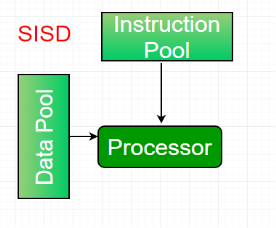
The speed of the processing element in the SISD model is limited(dependent) by the rate at which the computer can transfer information internally. Dominant representative SISD systems are IBM PC, workstations.
2. Single-instruction, multiple-data (SIMD) systems –
An SIMD system is a multiprocessor machine capable of executing the same instruction on all the CPUs but operating on different data streams. Machines based on an SIMD model are well suited to scientific computing since they involve lots of vector and matrix operations. So that the information can be passed to all the processing elements (PEs) organized data elements of vectors can be divided into multiple sets(N-sets for N PE systems) and each PE can process one data set.
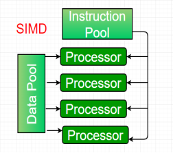
Dominant representative SIMD systems is Cray’s vector processing machine.
3. Multiple-instruction, single-data (MISD) systems –
An MISD computing system is a multiprocessor machine capable of executing different instructions on different PEs but all of them operating on the same dataset .
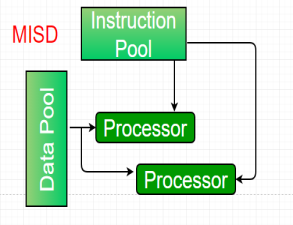
Example Z = sin(x)+cos(x)+tan(x)
The system performs different operations on the same data set. Machines built using the MISD model are not useful in most of the application, a few machines are built, but none of them are available commercially.
4. Multiple-instruction, multiple-data (MIMD) systems –
An MIMD system is a multiprocessor machine which is capable of executing multiple instructions on multiple data sets. Each PE in the MIMD model has separate instruction and data streams; therefore machines built using this model are capable to any kind of application. Unlike SIMD and MISD machines, PEs in MIMD machines work asynchronously.
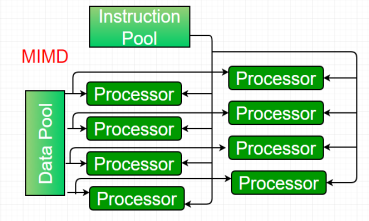
MIMD machines are broadly categorized into shared-memory MIMD and distributed-memory MIMD based on the way PEs are coupled to the main memory.
In the shared memory MIMD model (tightly coupled multiprocessor systems), all the PEs are connected to a single global memory and they all have access to it. The communication between PEs in this model takes place through the shared memory, modification of the data stored in the global memory by one PE is visible to all other PEs. Dominant representative shared memory MIMD systems are Silicon Graphics machines and Sun/IBM’s SMP (Symmetric Multi-Processing).
In Distributed memory MIMD machines (loosely coupled multiprocessor systems) all PEs have a local memory. The communication between PEs in this model takes place through the interconnection network (the inter process communication channel, or IPC). The network connecting PEs can be configured to tree, mesh or in accordance with the requirement.
The shared-memory MIMD architecture is easier to program but is less tolerant to failures and harder to extend with respect to the distributed memory MIMD model. Failures in a shared-memory MIMD affect the entire system, whereas this is not the case of the distributed model, in which each of the PEs can be easily isolated. Moreover, shared memory MIMD architectures are less likely to scale because the addition of more PEs leads to memory contention. This is a situation that does not happen in the case of distributed memory, in which each PE has its own memory. As a result of practical outcomes and user’s requirement , distributed memory MIMD architecture is superior to the other existing models.
Do you often get confused with the Intel’s processor line-up? Ever wondered which chipset is best for your requirements? Which is more compatible with your needs? One should look beyond the Core i branding and check the number of cores, Clock Speed, Turbo Boost and Hyper-Threading to truly understand the magnitude of power it generates.
Different processor families have different levels of efficiency, so how much they get done with each clock cycle is more important than the GHz number itself.
Intel’s current core processors are divided into three ranges(Core i3, Core i5 and Core i7), with several models in each range.The differences between these ranges aren’t same on laptop chips as on desktops. Desktop chips follow a more logical pattern as compared to laptop chips, but many of the technologies and terms, we are about to discuss, such as cache memory, the number of cores, Turbo boost and Hyper-Threading concepts is same. Laptop processors have to balance power efficiency with performance – a constraint that doesn’t really apply to desktop chips. Similar is the case with the Mobile processors.
Let’s start differentiating the processors on the basis of the concepts discussed below!
Concepts and Technologies
- Total number of cores present: Out of all differences between the intel processor ranges, this is one that will affect performance the most.
Having several cores can also drastically increase the speed at which certain programs run. The Core i3 range is entirely dual core, while Core i5 and i7 processors have four cores.It is difficult for an application to take advantage of the multicore system. Each core is effectively its own processor – your PC would still work (slowly) with just one core enabled. Having multiple cores means that the computer can work on more than one task at a time more efficiently.
Personal Computer | Intel Core i3 | Intel Core i5 | Intel Core i7 |
Number of Cores | 2 | 4 | 4 |
- What is Turbo Boost in processors?
This may be interesting, the slowest Core i3 chips runs at a faster speed than the base Core i5 and Core i7. This is where clock speed comes into the scenario.Let’s first define, What is Clock speed?
The GHz represents the number of clock cycles (calculations) a processor can manage in a second. Putting simply, a bigger number means a faster processor.
Examples: - 2.4GHz means 2,400,000,000 clock cycles.
Personal Computer | Intel Core i3 | Intel Core i5 | Intel Core i7 |
Clock Speed Range(Several Models) | 3.4GHz – 4.2GHz | 2.4GHz – 3.8GHz | 2.9GHz – 4.2GHz |
- Turbo Boost has nothing to do with fans or forced induction but is Intel’s marketing name for the technology that allows a processor to increase its core clock speed dynamically whenever the need arises. Core i3 processors don’t have Turbo Boost, but Core i5 and Core i7s do. Turbo Boost dynamically increases the clock speed of Core i5 and i7 processors when more power is required. This means that the chip can draw less power, produce less heat and only boost when it needs to. For example, although a Core i3-7300 runs at 4GHz compared to 3.5GHz for the Core i5-7600, the Core i5 chip can boost up to 4.1GHz when required, so will end up being quicker. A processor can only Turbo Boost for a limited amount of time. It is a significant part of the reason why Core i5 and Core i7 processors outperform Core i3 models in single-core-optimised tasks, even though they have lower base clock speeds.
Personal Computer | Intel Core i3 | Intel Core i5 | Intel Core i7 |
Turbo Boost | No | Yes | Yes |
- Note:
If a processor model ends with a K, it means it is unlocked and can be ‘overclocked’. This means you can force the CPU to run at a higher speed than its base speed all the time for better performance. - Cache memory: A processor’s performance isn’t only determined by clock speed and number of cores, though. Other factors such as cache memory size also play a part. When a CPU finds it is using the same data over and over, it stores that data in its cache. Cache is even faster than RAM because it’s part of the processor itself.
Here, bigger is better. Core i3 chips have 3- or 4MB, while i5s have 6MB and the Core i7s have 8MB.
Personal Computer | Intel Core i3 | Intel Core i5 | Intel Core i7 |
Cache Memory | 3 – 4MB | 4 – 6MB | 8MB |
- What is Hyper-Threading?
It’s one of the concepts which is a little confusing to explain, but also confuses as it’s available on Core i7 and Core i3, but not on the mid-range core i5. A little shocking, right? Normally we assume that we get more features as we go higher towards the processor range, but not here. Back to the concept, A thread in computing terms is a sequence of programmed instructions that the CPU has to process. For example: If a CPU consists of one core, it can process only one thread at once, so can only do one thing at once.
Hyper-Threading is a clever way to let a single core handle multiple threads. It essentially tricks operating system into thinking that each physical processor core is, in fact, two virtual (logical) cores. A two-core Core i3 processor will appear as four virtual cores in Task Manager, and a four-core i7 chip will appear as eight cores. Whereas, the current Core i5 range doesn’t have Hyper-Threading so can also only process four cores. Due to Hyper-Threading operating system is able to share processing tasks between these virtual cores in order to help certain applications run more quickly, and to maintain system performance when more than one application is running at once.
Personal Computer | Intel Core i3 | Intel Core i5 | Intel Core i7 |
Hyper-Threading | Yes | No | Yes |
From these, we conclude why Core i7 processors are the creme de la creme. Not only are they quad cores, they also support Hyper-Threading. Thus, a total of eight threads can run on them at the same time. Combine that with 8MB of cache and Intel Turbo Boost Technology, which all of them have, and you’ll see what sets the Core i7 apart from its siblings.
On the other side, it totally depends on the requirements, to choose a processor.
References:
1. “Digital Design”, M Morris Mano, Prentice Hall, Third Edition
2. “Computer organization” , Hamacher and Zaky, Fifth Edition
3. “Computer Organization and Design: The Hardware Software Interface” D. Patterson, J. Hennessy, Fourth Edition, Morgan Kaufmann
4. “ Microprocessors and interfacing-programming and hardware” Douglas V. Hall and SSSP Rao, McGraw-Hill ,Third Edition