Unit 1
Computer Graphics
“The use of computer systems to assist in the creation, modification, synthesis, analysis and optimization of a design of any product, machine or component of machine is defined as Computer Aided Design.”
“The use of computer systems to plan, manage and control the manufacturing operations by interfacing of computer system to manufacturing machine is defined as Computer Aided Manufacturing”
“Computer Graphics is the technology that deals with the generation, transformation and modification of a 2D of 3D model or simply a picture using a computer software or an application.”
“The construction of a geometric model by using the computer Graphics is called as Geometric Formulation.” Any 2D graphic element is constructed out of two or more points. While the the formulation of a 3D model requires two or more planes.
“Geometric Transormation is the change of the orientation, shape and size of the geometric model in the database and graphic image in the computer graphics.”
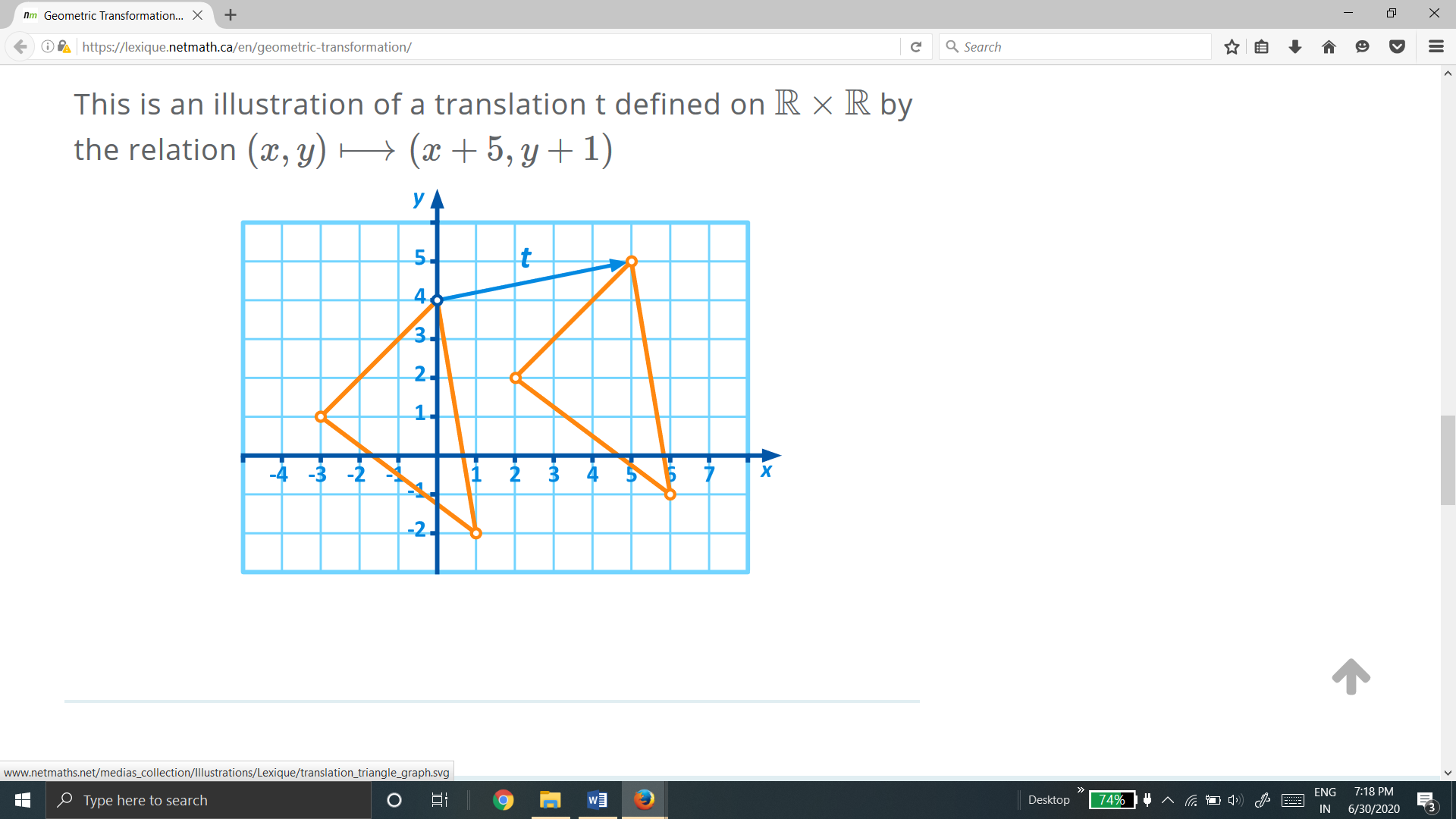
Basic Geometric Transformations:
The basic geometric transformation used in modelling in computer graphics are:
a) Translation
b) Shear
c) Rotation
d) Scaling
e) Reflection
1.2.1 Translation:
“Translation is defined as the movement of every point on the geometric model in the same direction by same distance.”
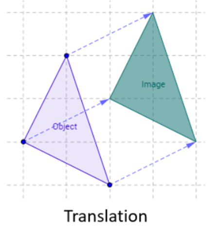
Consider a point  is translated by a distance
  in
in  direction and
  in
in  direction to a new position


The translation is equation is given by

Where,

 Original position of the point

 New position of the point
 Translation matrix
1.2.2 Shear:
“A transformation in which all points along a given line remain fixed while other points are shifted parallel to by a distance proportional to their perpendicular distance is shear transformation.”
Types of shear:
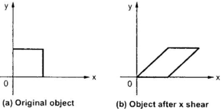
Fig. X – direction shear of graphic element
Consider a point  is subjected to sheer in X – direction as to occupy a new position
  . Then


Where,  = sheer parameter
The sheer transformation equation is given by

Where,
 = X – direction sheer matrix

ii. Y – direction shear:
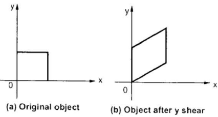
Fig. Y– direction shear of graphic element
Consider a point  is subjected to sheer in Y – direction as to occupy a new position
  . Then


Where,  = sheer parameter
The sheer transformation equation is given by

Where,
 = Y – direction sheer matrix

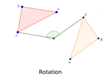
1.2.3 Rotation:
“A rotation is a transformation in which the object is rotated about a fixed point.”
Consider a point  is rotated about the origin (z-axis) by on an angle
  in counterclockwise direction to a new position
 .
.
Let,  constant distance of point from the origin
 Original angular position of the point from the horizontal


Where  Rotation matrix
1.2.4 Scaling:
“A scaling transformation alters size of an object.”
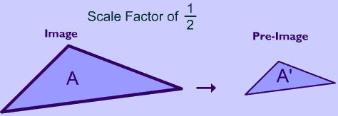
Fig. Scaling
Consider the point  be any point of the object to be scaled and
  be the corresponding point on the scaled object.
Let  = Scaling factor in X –direction
 = Scaling factor in Y –direction


The scaling transformation equation is given by


Where,  Scaling matrix
1.2.5 Reflection:
“Reflection is the transformation in which the object is flipped or reflected about a line.”
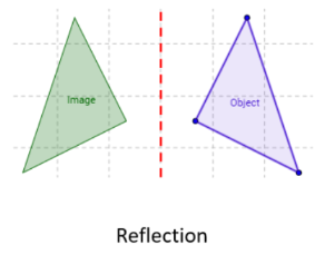
Reflection can be about various lines such as:
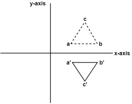
Fig. Reflection about X- axis
Consider a point  is reflected about X – axis to a new position
  .
.
Then 

The transformation equation is given by

Where  reflection matrix about X - axis

b. Reflection about Y- axis:
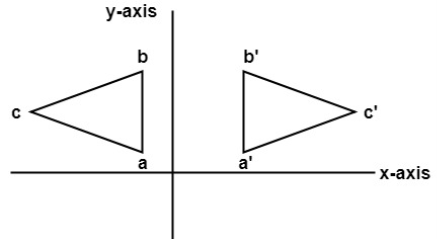
Fig. Reflection about Y- Axis
Consider a point  is reflected about Y – axis to a new position
  .
.
Then 

The transformation equation is given by

Where  Reflection matrix about Y – axis

c. Reflection about origin:
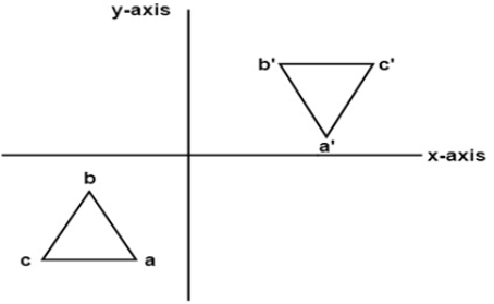
Fig. Reflection about origin
Consider a point  is reflected about origin to a new position
Then 
The transformation equation is given by

Where  Reflection matrix about origin
d. Reflection about line 
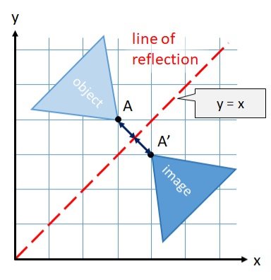
Reflection about y=x
Consider a point  is reflected about the line
  to a new position
Then 

The transformation equation is given by

Where  Reflection matrix about the line

e. Reflection about line 
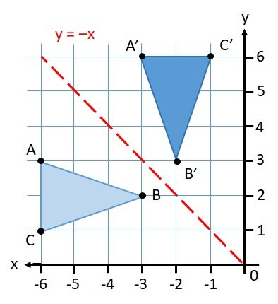
Fig. Reflection about 
Consider a point  is reflected about the line
  to a new position
Then 

The transformation equation is given by

Where  Reflection matrix about

Example of representing coordinates into a homogeneous coordinate system:
For two-dimensional geometric transformation, we can choose homogeneous parameter h to any non-zero value. For our convenience take it as one. Each two-dimensional position is then represented with homogeneous coordinates (x, y, 1).
Basic 2D geometric transformation in homogeneous co-ordinate system are:
1.3.1 Translation


Where  New position of point
 Original position of point
 = Translation matrix
1.3.2 Sheer
(i) X – direction sheer

Or 
Where  X – direction sheer matrix
(ii) Y – direction sheer

Or 
Where  Sheer matrix in Y – direction
1.3.3 Rotation
(i) Anticlockwise rotation

Or 
 Rotation matrix
(ii) Clockwise rotation

Or 
Where  Rotation matrix
1.3.4 Scaling

Or 
Where  Scaling matrix
1.3.5 Reflection
1) Reflection about X- axis

Or 
Where  Reflection matrix about X – axis
2) Reflection about Y – axis

Or 
Where  Reflection about Y – axis
(iii) Reflection about origin

Or 
Where  Reflection matrix about origin
(iv) Reflection matrix about 

Or 
Where  Reflection matrix about
(v) Reflection matrix about 

Or 
Where  Reflection matrix about
A number of transformations or sequence of transformations can be combined into single one called as composition. The resulting matrix is called as composite matrix. The process of combining is called as concatenation.
Suppose we want to perform rotation about an arbitrary point, then we can perform it by the sequence of three transformations
The ordering sequence of these numbers of transformations must not be changed. The composite transformation is performed by multiplying matrix in order from right to left side.
Example showing composite transformations:
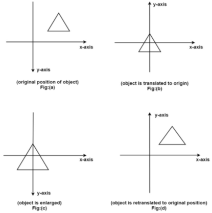
The enlargement is with respect to center. For this following sequence of transformations will be performed and all will be combined to a single one
Step1: The object is kept at its position as in fig (a)
Step2: The object is translated so that its center coincides with the origin as in fig (b)
Step3: Scaling of an object by keeping the object at origin is done in fig (c)
Step4: Again translation is done. This second translation is called a reverse translation. It will position the object at the origin location.
Mathematical representation of composite
Transformation (Concatenated matrix):

Then the object is scaled
The scaling matrix is given by

Finally, the object is given translated back It becomes inverse translation 

Then the concatenated matrix is given by


and 
General Pivot Point Rotation or Rotation about Fixed Point:
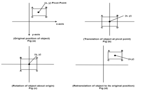
1) For it first of all rotate function is used. Sequences of steps are given below for rotating an object about origin.
2) Translate object to origin from its original position as shown in fig (b)
3) Rotate the object about the origin as shown in fig (c).
4) Translate the object to its original position from origin. It is called as reverse translation as shown in fig (d).
The concatenated matrix of the above sequence is given by


“These are also called as opposite transformations.”
If T is a translation matrix than inverse translation is representing using T-1. The inverse matrix is achieved using the opposite sign.
During the development of composite transformation matrix, many a times, it is necessary to use the inverse of some basic geometric transformation matrices.
Various Geometric Transformation matrices for 2D geometric transformation are:
1) Inverse translation

2) Inverse Rotation

3) Inverse Scaling

4) Inverse Reflection


Note: The inverse reflection matrix is some as that of the reflection matrix.
There are three major types of coordinate system commonly used in CAD modeling.
“The model coordinate system is the reference space of model with respect to which all the geometrical data of model is stored in database.”
This is the only coordinate system that modelling software recognizes when storing or retrieving the graphical information in or from model database.
The CAD software stores the graphical information in the model database with reference to the coordinate system known as model coordinate system.
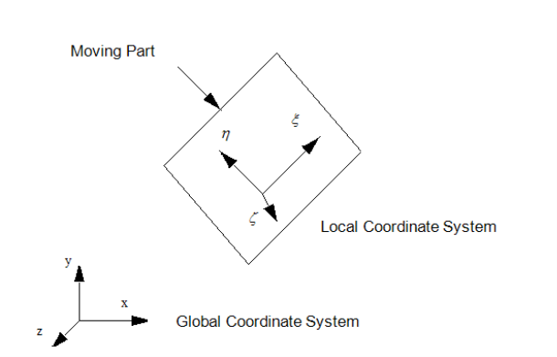
2. User Coordinate System (UCS) or Local Coordinate System or Working Coordinate System (WCS):
“User Coordinate System is defined by the user for the convenience of input of the graphical information.”
In CAD modelling, the user inputs the graphical information with reference to the coordinate system known as user coordinate system.
If the geometric model has a complex geometry or a specific orientation, it is highly inconvenient to input the graphical data in a model coordinate system.
3. Screen Coordinate system:
“Screen Coordinate system is a 2D Cartesian Coordinate System whose origin is located at the corner of the graphics display screen.”
This system is display-device dependent.
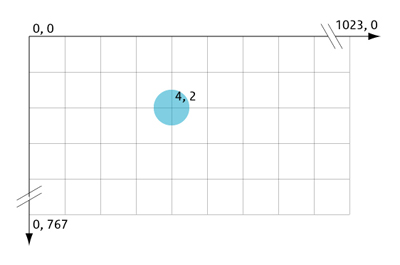
Fig. Screen Coordinate System
“Mapping of the Geometric model changes the graphical description of model from one coordinate system to another without changing the position, orientation, size and shape of the model.”
In CAD modelling, the user inputs the graphical information with reference to the working or user coordinate system (UCS or WCS) of the sketch plane, while CAD software stores the graphical information in the model database with reference to Model Coordinate System (MCS).
Mapping is used to convert the coordinates of points on the model from one coordinate system to another.
Types of Geometric Mapping:
1.7.1 Translation Mapping
“If the axes of the two coordinate systems are parallel, then the mapping is called translation mapping.”
Let, dx = distance of the origin of original system (O) from the origin of the new coordinate system (O’) along X-direction.
dy = distance of the origin of original system (O) from the origin of the new coordinate system (O’) along Y-direction.
Coordinate of point P in new coordinate system are:
x’ = x + dx
y’ = y + dy
 The translation mapping matrix is given by
 Translation mapping matrix

1.7.2 Rotational Mapping:
“If both the coordinate systems have common origin but the axes are at an angle, then the mapping is called rotational mapping.”
Let, ɸ = angle made by the axes of original coordinate system with the axes of new coordinate system.
Coordinate of point P in new coordinate system are:
X' = x cosɸ - y sin ɸ
y' = x sin ɸ + y cos ɸ
The rotational mapping matrix is given by
 Rotational mapping matrix

1.7.3 General Mapping:
“It is the combination of rotational and translational mapping.”
Coordinate of point P in new coordinate system are:
x’ = x cosɸ - y sin ɸ+ dx
y' = x sin ɸ + y cos ɸ+ dy
The general mapping matrix is given by:


The geometric transformations play a vital role in generating images of three Dimensional objects with the help of these transformations. The location of objects relative to others can be easily expressed. Sometimes viewpoint changes rapidly, or sometimes objects move in relation to each other. For this number of transformation can be carried out repeatedly.
The method of 2D transformations can be extended to 3D by including Z-coordinate.
Some of the 3D geometric transformation matrices are as follows:
1.8.1 Translation matrix:
 Translation matrix
1.8.2 Rotation matrices:
(i) Rotation about z – axis
 Rotation matrix (about z – axis)
 Rotation angle about z - axis
(ii) Rotation about x - axis
 Rotation matrix (about x – axis)
 Rotation angle about x - axis
iii) Rotation about Y-axis
 Rotation matrix (about Y-axis)
 Rotation angle about Y – axis
1.8.3 Scaling matrix:
 Scaling matrix
1.8.4 Reflection Matrix:
(i) Reflection about x-y plane
 Reflection matrix (about x – y plane).
(ii) Reflection about y-z plane
 Reflection matrix (about y – z plane).
(iii) Reflection about x-z plane
 Reflection matrix (about x – z plane).
“It is the process of converting a 3D object into a 2D object.”
It is also defined as mapping or transformation of the object in projection plane or view plane. The view plane is displayed surface.
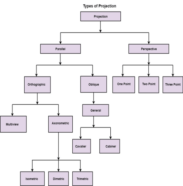
1.9.1 Perspective Projection:
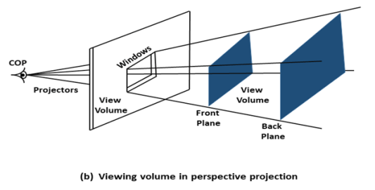
In perspective projection farther away object from the viewer, small it appears. This property of projection gives an idea about depth. The artist use perspective projection from drawing three-dimensional scenes.
Two main characteristics of perspective are vanishing points and perspective foreshortening. Due to foreshortening object and lengths appear smaller from the center of projection. More we increase the distance from the center of projection, smaller will be the object appear.
Vanishing Point:
“It is the point where all lines will appear to meet. There can be one point, two point, and three point perspectives.”
One Point:
“There is only one vanishing point.”
Two Points:
“There aretwo vanishing points. One is the x-direction and other in the y –direction.”
Three Points:
“There are three vanishing points. One is x second in y and third in two directions.”
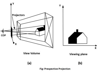
In Perspective projection lines of projection do not remain parallel. The lines converge at a single point called a center of projection. The projected image on the screen is obtained by points of intersection of converging lines with the plane of the screen. The image on the screen is seen as of viewer's eye were located at the centre of projection, lines of projection would correspond to path travel by light beam originating from object.
Important terms related to perspective
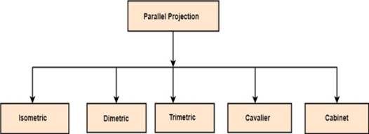
1.9.2 Parallel Projection:
Parallel Projection use to display picture in its true shape and size.
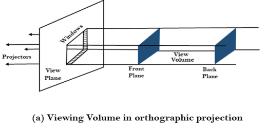
“When projectors are perpendicular to view plane then is called orthographic projection.”
The parallel projection is formed by extending parallel lines from each vertex on the object until they intersect the plane of the screen. The point of intersection is the projection of vertex.
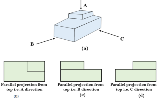
Parallel projections are used by architects and engineers for creating working drawing of the object, for complete representations require two or more views of an object using different planes.
