Unit 3
Finite Element Analysis
The Finite Element Method (FEM) is a numerical technique to find approximate solutions of partial differential equations. It was originated fromthe need of solving complex elasticity and structural analysis problems in Civil, Mechanical and Aerospace engineering. In a structural simulation, FEM helps in producing stiffness and strength visualizations. It also helps to minimize material weight andits cost of the structures. FEM allows for detailed visualization and indicates the distribution of stresses and strains inside the body of a structure. Many of FE software are powerful yet complex tool meant for professional engineers with the training and education necessary to properly interpret the results.
3.1.1 Need of FEA
Design geometry is a lot more complex; and the accuracy requirement is a lot higher. We need
3.1.2 Terminologies in FEA
Continuum
A continuous sequence in which adjacent elements are not perceptibly different from each other, but the extremes are quite distinct. A continuum is a complex region which defines a geometry. Any continuum/domain can be divided into a number of pieces with very small dimensions.
Element
Node
Each element has one or more node. Each element is connected to each other at these nodes.

Object or Continuum
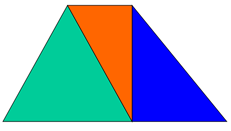
Element
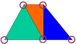
Nodes
Domain
The original domain is considered as an assemblage of number of such small elements.
Load
Loads are used to represent inputs to the system. They can be in the forms of forces, moments, pressures, temperature, or accelerations. There are three types of load
Field Variables
The field variables are the dependent variables of interest governed by the differential equation.
Boundary Conditions
Constraints
Displacement boundary conditions and surface loading conditions are the constraints.
3.1.3 Degree of Freedom
Consider a two-dimensional case with a single field variable φ(x, y). The triangular element described is said to have 3degrees of freedom, as three nodal values of the field variable are required to describe the field variable everywhere in the element (scalar).
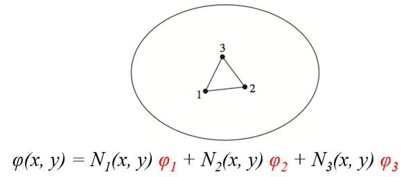
In general, the number of degrees of freedom associated with a finite element is equal to the product of the number of nodes and the number of values of the field variable(and possibly its derivatives) that must be computed at each node.
3.1.4 Discretization Technique
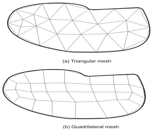
The need of finite element analysis arises when the structural system in terms of its either geometry, material properties, boundary conditions or loadings is complex in nature. For such case, the whole structure needs to be subdivided into smaller elements. The wholestructure is then analyzed by the assemblage of all elements representing the complete structure including its all properties. The subdivision process is an important task in finite element analysis and requires some skill and knowledge. In this procedure, first, the number, shape, size and configuration of elements have to be decided in such a manner that the real structure is simulated as closely as possible. The discretization is to be in such that the results converge to the true solution. However, too fine mesh will lead to extra computational effort. Fig. shows a finite element mesh of a continuum using triangular and quadrilateral elements. The assemblage of triangular elements in this case shows better representation of the continuum. The discretization process also shows that the more accurate representation is possible if the body is further subdivided into some finer mesh.
3.1.5 General Procedure of FEA
To summarize in general terms how the finite element method works we list main steps of the finiteelement solution procedure below.
3.1.6 Application of FEA in various field.
3.1.7 Mesh
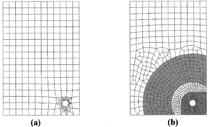
Mesh is a way of communicating geometry to the solver, the accuracy of the solution is primarily dependent on the quality of the mesh. The better the mesh looks, the more accurate the solution is. A good-looking mesh should have well-shaped elements, and the transition between densities should be smooth and gradual without skinny, distorted elements.
The mesh transition from .05 to .5 element size without control of transition (a) creates irregular mesh around the hole which will yield disappointing results.
3.1.8 P and h formulation
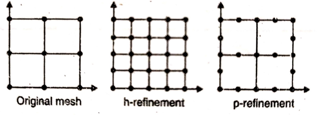
In finite element analysis, solution accuracy is judged in terms of convergence as the element “mesh”is refined. There are two major methods of mesh refinement.
In the first, known as h-refinement, mesh refinement refers to the process of increasing the number of elements used to model a given domain, consequently, reducing individual element size.
The objective of mesh refinement in either method is to obtain sequential solutions that exhibit asymptotic convergence to values representing the exact solution.
3.1.9 Advantages of FEA
3.1.10 Disadvantages of FEA
3.2.1 Shape Function
The values of the field variable computed at the nodes are used to approximate the values at non-nodal points (that is, in the element interior) by interpolation of the nodal values. For the three-node triangle example, the field variable is described by the approximate relation
φ(x, y) = N1(x, y) φ1+ N2(x, y) φ2+ N3(x, y) φ3
where φ1, φ2, andφ3are the values of the field variable at the nodes, and N1, N2, and N3are the interpolation functions, also known as shape functions or blending functions.
In the finite element approach, the nodal values of the field variable are treated as unknown constants that are to be determined. The interpolation functions are most often polynomial forms of the independent variables, derived to satisfy certain required conditions at the nodes.
The interpolation functions are predetermined, known functions of the independent variables; and these functions describe the variation of the field variable within the finite element.
Let  be the natural coordinate of 1D element, then the shape functions are given by


3.2.2 Stiffness Matrix
The primary characteristics of a finite element are embodied in the element stiffness matrix. For a structural finite element, the stiffness matrix contains the geometric and material behavior information that indicates the resistance of the element to deformation when subjected to loading. Such deformation may include axial, bending, shear, and torsional effects. For finite elements used in nonstructural analyses, such as fluid flow and heat transfer, the term stiffness matrix is also used, since the matrix represents the resistance of the element to change when subjected to external influences.
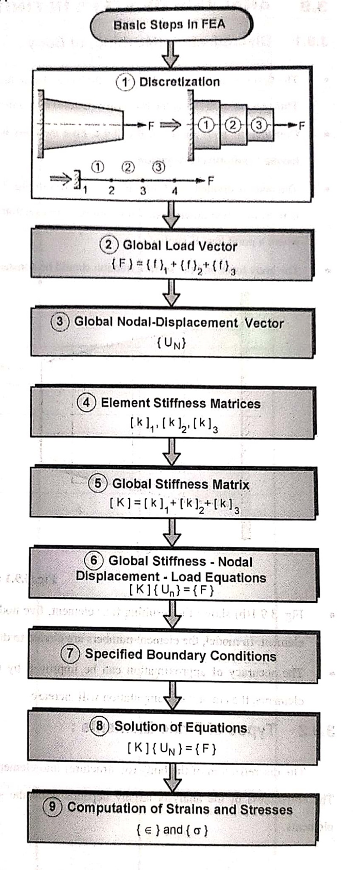
3.2.3 Steps to solve a FEA Problem
Step I: Discretization
Discretization is a process of dividing a body into finite number of elements.
Step II: Formulation of Global Load Vector
The elemental force vectors in the global coordinate system for all elements are assembled to form the global load vector {F} for the entire body.
The global Load Vector is given by,

Where F1, F2, F3, …, FN are the loads acting at nodes 1,2,3,…,N respectively
Step III: Formulation of Global Nodal Displacement Vector
The global nodal displacement vector {UN} is formed for the entire body.
The global nodal displacement vector is given as

Where U1, U2, U3,…, UN are the displacements acting at nodes 1,2,3,…,N respectively
Step IV: Formulation of elemental stiffness matrices
After the body is discretized, the elemental stiffness matrix is formulated for all discretized elements.
Consider a one-dimensional rod element as shown in fig.

It has two nodes. Each node has one degree of freedom
Let
l = length of element
A = Cross-sectional area
E = modulus of Elasticity
f1 = Force acting at node 1
f2 = Force acting at node 2
u1 = displacement of node 1
u2 = displacement of node 2
Stiffness of rod element is

From fig,

And 
The above equations in matrix form can be written as

Where,
{f} =  = elemental force vector
[k] = = elemental stiffness matrix
{uN} =  = elemental nodal displacement vector
Step V: Formulation of Global Stiffness Matrix
The global stiffness matrix is formed from the elemental nodal stiffness matrices.
Such as

Step VI: Assembly of Global Stiffness – Nodal Displacement – Load Equations
This equation is called as Finite element equation.
If N is the total degree of freedom of the body.
Step VII: Specify boundary conditions
The specified boundary conditions are incorporated in equilibrium equation by using elimination approach or penalty approach.
Step VIII: Solution of Equations
After including the boundary conditions, the modified equations are solved for the unknown nodal displacements.
Step VIII: Computation of Elemental stresses and strains
Elemental strains are calculated from nodal displacements by
Where,
 = Element strain
 = element strain-nodal displacement matrix
And from the strain calculated, stresses can be calculated as

Where,  = element stress
3.2.4 Properties of stiffness matrix
3.2.5 Numerical on Spring element in series and parallel
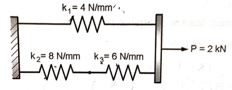
Fig shows a cluster of three springs. Using the finite element method, determine:
1) The deflection of each spring
2) The reaction force at support
Solution:
Given: k1 = 4N/mm
k2 = 8N/mm
k3 = 6N/mm
U1 = 0
P3 = 2000 N
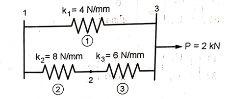
Three springs can be treated as three 1D spar element
Element Number | Global Node number ‘n’ of | |
Local Node 1 | Local Node 2 | |
1 | 1 | 3 |
2 | 1 | 2 |
3 | 2 | 3 |
2. Element stiffness matrix
For Element 1,

For Element 2,

For Element 3,

3. Global stiffness matrix


4. Global load vector

5. Global nodal displacement vector

6. Global stiffness-nodal displacement relationship
Hence after the assembly, the equilibrium equation is,

At node 1, U1=0, there is rigid support.
Using elimination approach, first rows and columns are eliminated.
7. Nodal Displacements

Solving two equations for two unknowns, we get,
U2 = 115.38 mm and U3 = 269.23 mm
Deflection of Spring 1 = U3 – U1 = 269.23 – 0 = 269.23 mm
Deflection of Spring 2 = U2 – U1 = 115.38 – 0 = 115.38 mm
Deflection of Spring 3 = U3 – U2 = 269.23 – 115.38 = 153.84 mm
8. Reaction force at support
We have,
12U1 – 8U2 – 4U3 = R
12 x 0 – 8 x 115.38 – 4 x 269.23 = R
R = -2000 N
3.2.6 Numerical on Composite bar element
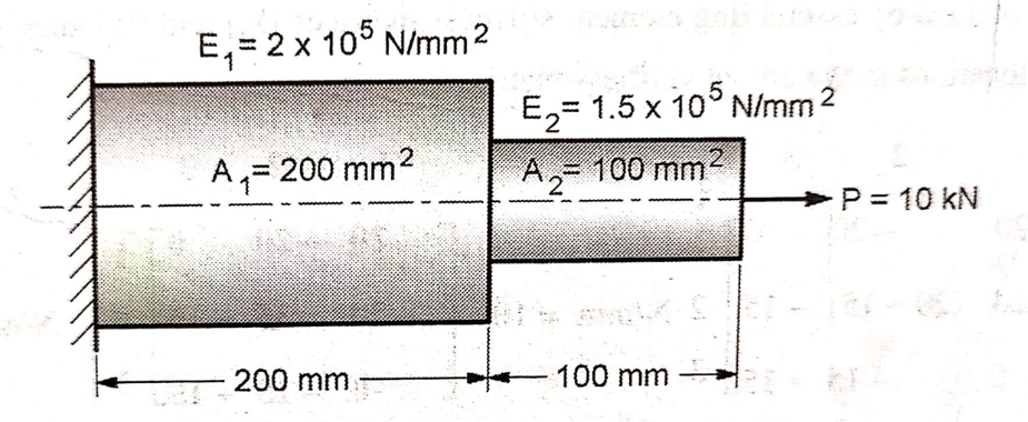
An axial step bar is shown in figure. Determine the deflection, stresses in element and reaction force.
Solution:
Given: l1 = 200 mm
l2 = 100 mm
A1 = 200 mm2
A2 = 100 mm2
E1 = 2 x 10⁵ N/ mm2
E2 = 1.5 x 10⁵ N/ mm2
P = 10000 N

Fig shows an assemblage of two 1D spar element. Its elemental connectivity is given below
Element Number | Global Node number ‘n’ of | |
Local Node 1 | Local Node 2 | |
1 | 1 | 2 |
2 | 2 | 3 |
2. Element stiffness matrix
For Element 1,

For Element 2,

3. Global stiffness matrix


4. Global load vector

5. Global nodal displacement vector

6. Global stiffness-nodal displacement relationship
Hence after the assembly, the equilibrium equation is,

At node 1, U1=0, there is rigid support.
Using elimination approach, first rows and columns are eliminated.
7. Nodal Displacements

Solving two equations for two unknowns, we get,
U2 = 0.05 mm and U3 = 0.117 mm

8. Stresses in elements:
Stresses are given by,

In element 1,

In element 2,

9. Reaction force at support
We have,
104 (20U1 – 20U2 ) = R
104(20 x 0 – 20 x 0.05) = R
R = -10 x 103kN
3.2.7 Temperature Effects on 1D Element
Sometimes in a body, in addition to the stresses induces due to applied loads, the thermal stresses are also induced due to change in temperature.
Including the temperature effect, global load vector {F} is given by,

The initial strain due to change in temperature, in two noded one-dimensional element is given by,

Where,
 = Change in temperature
 = coefficient of thermal expansion
The stresses is given by,

3.3.1 Introduction to 2D trusses
Figure shows a typical 2D plane truss. Such trusses can be analyzed using the method of joints and the method of sections.
FEM can be effectively used for the analysis of trusses and to determine displacements of joints.
3.3.2 Elemental Stiffness matrix for 2D trusses.
Elemental stiffness matrix for 2D trusses are given by
Where,


 and
and are the coordinates of nodes.
And

3.3.3 Global Stiffness Matrix
All elemental Stiffness matrices are assembled to form Global Stiffness Matrix such as

3.3.4 FEA equation for 2D truss
The relationship between the global stiffness matrix [K], global nodal displacement vector {UN} and global load vector {f} is expressed as
{f} = [K]{UN}
3.3.5 Element Stress Calculation
The stress at any point within the 2D truss element is given by
3.3.6 Numerical on 2D Trusses
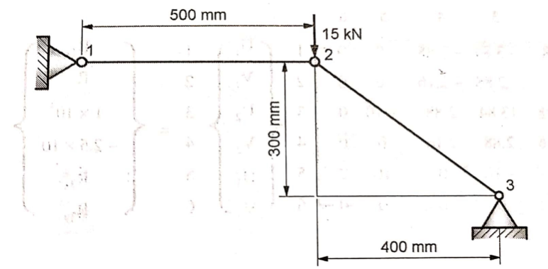
The two bar truss is shown in fig. The modulus of elasticity for four bar material is 70 x 103 N/mm2 and cross sectional area of each element is 200 mm2. Determine
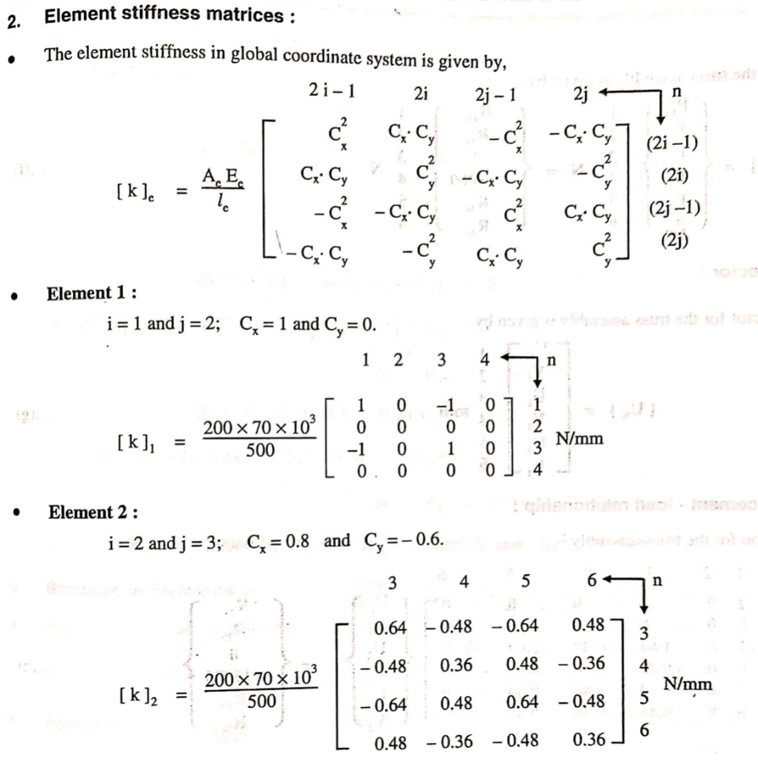
1) The element stiffness matrix
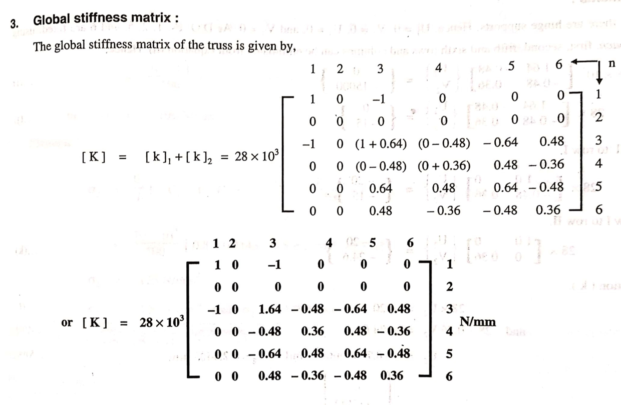
2) The global stiffness matrix
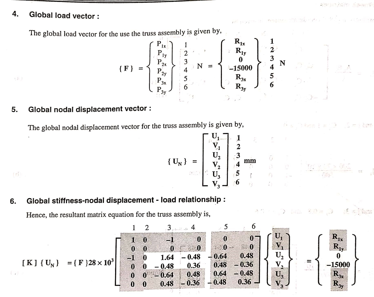
3) The nodal displacements
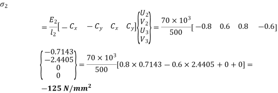
4) The stresses in each elements
5) The reaction forces
Solution
Given: E = 70 x 103 N/mm2 A = 200 mm2
l1 = 500 mm P2y = -15 kN

From fig,

Table below shows the element connectivity in the assembly
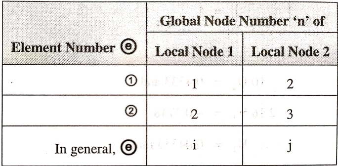
The values for Cxand Cy for all elements are

7. Nodal Displacements:

From the above equation, by solving for two unknowns
U2 = -0.7143 mm and V2 = -2.4405 mm
8. Reaction forces at support
28 x 103 [U1 –U2] = R1x
28 x 103 [0–(-0.7143)] = R1x
R1x= 20000 N
R1y = 0
28 x 103 [-0.64U2+0.48V2] = R3x
28 x 103 [-0.64 x (-0.7143) +0.48(-2.4405)] = R3x
R3x= -20000 N
28 x 103 [-0.48U2-0.36V2] = R3y
28 x 103 [-0.48(-0.7143) -0.36(-2.4405)] = R3y
R3y = 15000 N
R1x =20000 N R1y = 0 R3x =-20000 N R3y=15000 N
10. Stresses in Elements

For element 1,

For element 2,
References:
1. Ibraim Zeid, Mastering CAD/CAM – Tata McGraw Hill Publishing Co. 2000
2. Segerling L. J. - Applied Finite Elements Analysis, John Wiley and Sons
3. Seshu P. Text book of Finite Element Analysis, PHI Learning Private Ltd. New Delhi, 2010
4. Rao P. N., Introduction to CAD/CAM Tata McGraw Hill Publishing Co.
5. B. S. Pabla, M. Adithan, CNC Machines, New Age International, 1994
6. Groover M.P.-Automation, production systems and computer integrated manufacturing‘ - Prentice Hall of India
7. Ian Gibson, David W. Rosen, Brent Stucker, Additive Manufacturing Technologies: Rapid Prototyping to Direct Digital Manufacturing, Springer
8. Geoffrey Boothroyd, Peter Dewhurst, Winston A. Knight, Product Design for Manufacture and Assembly, Third Edition ,CRC Press
9. Antti Saaksvuori, Anselmi Immonen, Product Life Cycle Management -Springer, 1st Edition, 2003


