Unit 4
Computer Aided Manufacturing
“CAM is the use of computer systems to plan, manage and control the operations of manufacturing plant through either direct or indirect computer interface with the plant’s production resources.”
4.1.1 Numerical Control (NC)
“NC (numerical control) machine tools are the machine tool, of which the various functions are controlled by : letters , numbers and symbols.”
The NC machine tool runs on a program fed to it; without human operator. The NC program consist of a set of instruction or statement for controlling the motion of the drives of the machine tools as well as the motion of the cutting tool.
4.1.2 Components of NC Machine Tool System
- Using the part drawing and the cutting parameters, the part program is written.
- The part program is a set of step by instruction to the machine tool for carrying out the operation.
- Method use for part programming
2. Program Tape:
- The program is entered on the tape in the form of punched holes. The holes are punched with the help of punching machine.
- The program tape is read by the tape reader.
- The controller takes input from the tape reader.
4.1.3 Advantages of NC machine tools
• Cycle time reduction
• Complex machining operation
• High degree of accuracy
• Less inspection required
• Reduction of scrap and wastage
• Increasing productivity
• Lower tooling cost
• Reduction of human error
• Greater operation safety
• Greater operation efficiency
• Reduction space required
• Operator skill-level reduced
4.1.4 Limitation of NC machine tools
4.2.1 For flat and prismatic part
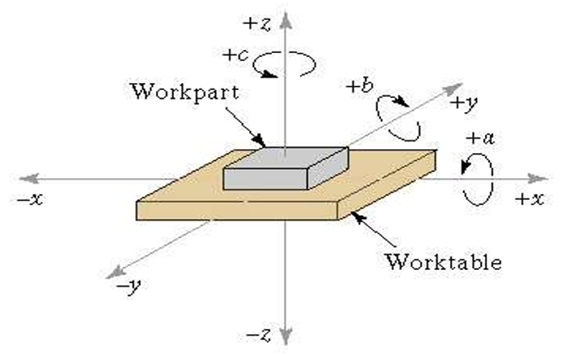
4.2.2 For rotational parts
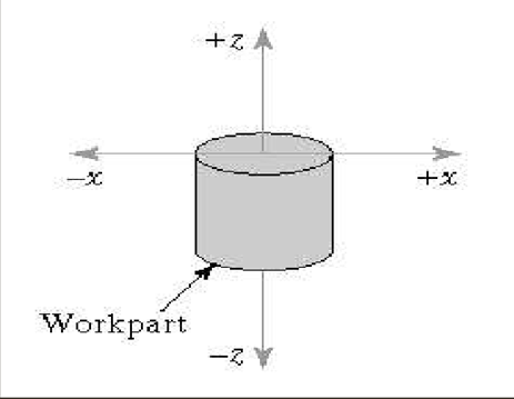
Z-axis: Always aligned with the spindle that imparts cutting power. This spindle might rotate the work-piece as in a lathe, it might rotate a tool as in a milling machine. It is perpendicular to work-holding surface if there is no such spindle. Positive motion in z axis tends to increase the separation between the work-piece and the tool
X axis: Positioning the moving element, parallel to the work-holding surface, horizontal (if possible). On machines with rotating work-pieces, it is radial and parallel to the cross-slide On machines with rotating tools.
4.2.3 Absolute and Incremental Coordinate System
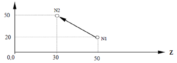
In incremental programming, the end point is specified with reference to the current tool position.
Absolute traverse to N1, then to N2
X20.0 Z50.0 X50.0 Z30.0
Absolute traverse to N1, incremental to N2
X20.0 Z50.0 U30.0 W-20.0
CNC Machine Tools
Components of CNC Machine Tool
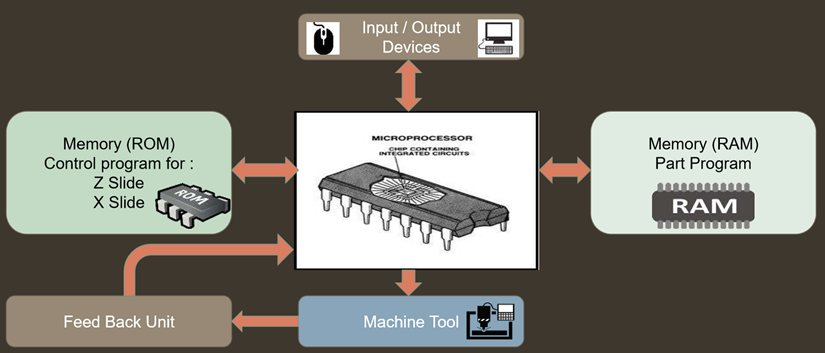
Components of CNC Machine Tools
Classification of CNC Machine Tool System
A] Classification based on type of feedback systems
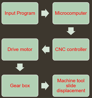
1. Open Loop Type CNC Machine
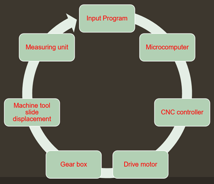
2. Closed Loop type CNC Machine
B] According to type of tool motion control:
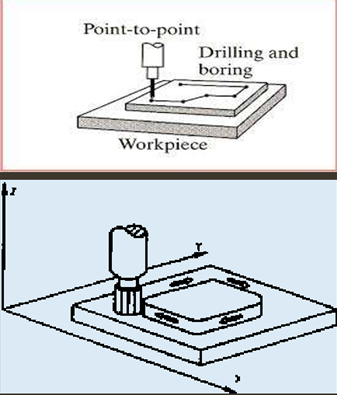
1. Finite Position Control CNC Machine
In point to point CNC machines, the movement of cutting tool from one predefined position to another predefined position is important, while the path along which this tool moves is irrelevant. Commonly used in drilling & punching operations.
Straight cut line control mode is the extension version of point to point method, straight cut is obtained controlling the movement of tool with controlled feed rate in one of the axis direction at a time. Commonly used in Face milling, pocket milling and step turning operations.
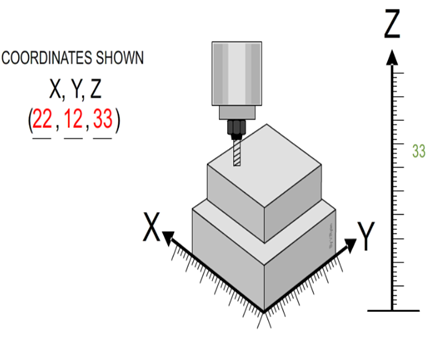
2. Continuous path control CNC Machine
C] According to programming Methods
1. Absolute Programming CNC Machine
In Cartesian coordinate geometry system using absolute measurement, each point is always specified using same zero established for a given coordinate system.
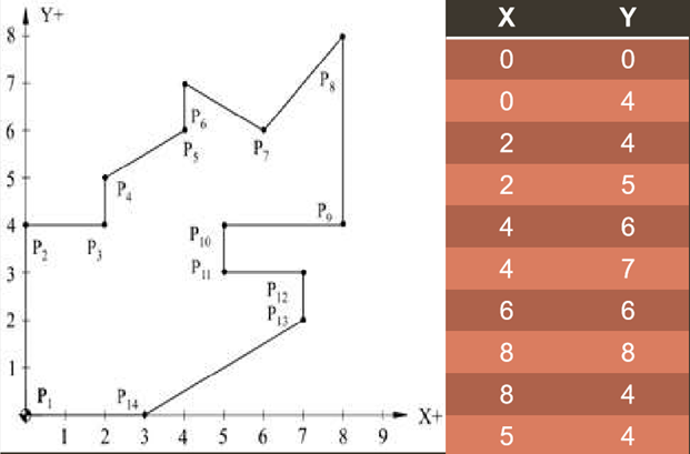
Absolute Programming
2. Incremental Programming CNC Machine
In Cartesian coordinate geometry system using incremental measurement, each point is specified using the path differential from the preceding point position. So in such programming, controller must store and process additional path measurement.
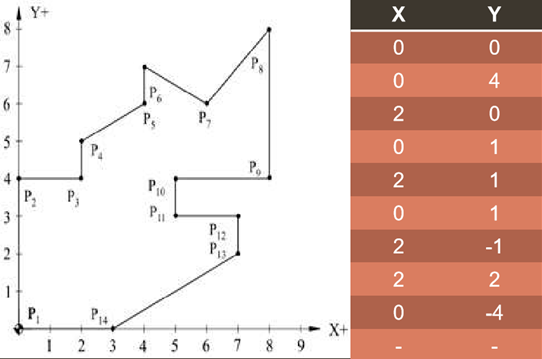
Incremental Programming
D] According to type of controllers
1. Hybrid Controller CNC Machine
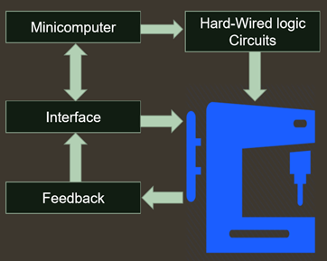
1. Hard wired logic circuits: It performs those functions for which they are best suited, such as feed rate generation and interpolation.
2. Soft wired computer: The computer performs the remaining control functions plus other duties not normally associated with a conventional hard-wired controller.
2. Stage Controller CNC Machine
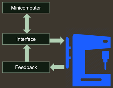
It uses a computer to perform all the functions.
The interpolation, feed rate generation and all other functions are performed by the computer with the help of software.
The only hard-wired elements are those required to interface the computer with machine tool and operator’s console.
Working Principle of CNC Lathe
A CNC lathe is typically designed to utilize modern versions of carbide tooling and processes. A part can be designed for customization, and the machine’s tool paths are often programmed using the CAD or CAM processes. However, a programmer can manually design a part or tool path as well. The resulting G-Code computer file is then uploaded to the CNC machine, and the machine will then automatically produce the desired parts for which it was programmed to design.
Turning Centre
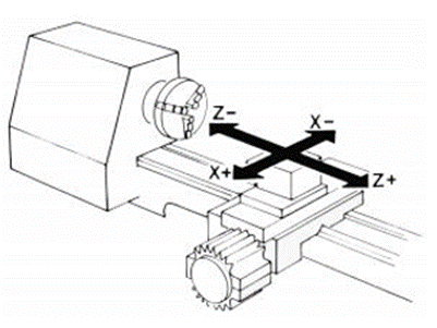
Turning Machine
Reference points or zero points
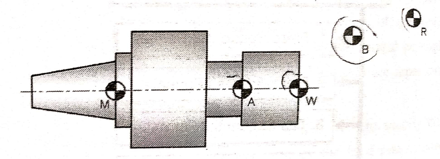
Origin is always located at some position on M/C table (usually at south west corner/Lower left-hand) of the tables & all tool location are defined W.R.T. this zero
2. Workpiece Zero or Fixed Zero (A)
Very common with CNC M/C used now a days. Operator gas lobeity to set zero point at any convenient position on M/C table. Blocking point is the workpiece zero point
3. Program Zero Point (W)
Program zero point is the starting point of workpiece blank
4. Start point (B)
Start point is to be determined in the program
5. Reference point (R)
The reference is to be determined by measuring system. The distsnce between R and M must be known. Normally R is not fixed.
Milling Machine

3 axes milling machine
Reference system in milling machine
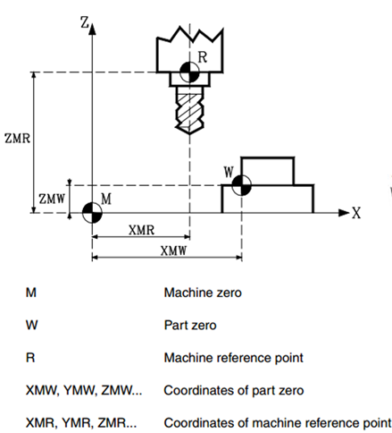
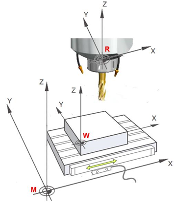
M – Machine Zero or home: This is set by the manufacturer as the origin of the coordinate system of the machine.
W – Part zero or point of origin of the part: This is the origin point that is set for programming the measurements of the part. It can be freely selected by the programmer.
R – Machine Reference point. This is a point on the machine established by the manufacturer around which the synchronization of the system is done. The control positions the axis on this point.
Part Program
The part program is the set of machining instructions, written in standard format, for the CNC machine.
The coded instructions or commands listed in a logical sequence to have a machine tool perform a specific task or a series of tasks in order to produce a finished product in the minimum amount of time.
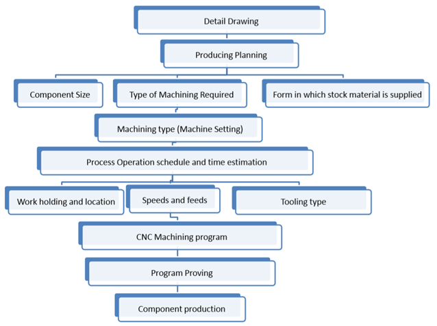
Steps involved in Part Programming
Programming Format
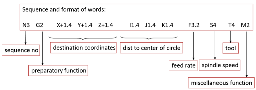
% Program Number.
N Sequence Number (Block Identification Number).
G Preparatory functions (G00 to G99). This prepares the M/C for next operation.
X,Y,Z Primary motion Dimension in the X,Y,Z direction respectively.
U,V,W Secondary motion Dimension in the X,Y,Z direction respectively.
P,Q,R Tertiary motion Dimension in the X,Y,Z direction respectively.
I,J,K Distance to the are center or thread leads parallel to X,Y,Z respectively.
A,B,C Angular Dimension around in the X,Y,Z direction respectively.
R Parameters.
F Feed rate.
S Spindle Speed/Cutting Speed.
T/D Tool number.
M Miscellaneous function (Machine Codes)
EOB End of Block.
Part Programming for CNC
The transfer of an engineering blueprint of a product to a part program can be performed manually using a calculator or with the assistance of a computer language. A part programmer must have an extensive knowledge of the machining processes and the capabilities of the machine tools. In this section, we describe how the part programmers execute manually the part programs.
First, the machining parameters are determined. Second, the optimal sequence of operations is evaluated. Third, the tool path is calculated. Fourth, a program is written. Each line of the program, referred to as a block, contains the required data for transfer from one point to the next.
A typical line for a program is given below.
N100 G91 X -5.0 Y7 .0 F100 S200 T01 M03 (EOB)
1. CHARACTER: A single alphanumeric character value or the "+" and "-" sign.
2. WORD: A series of characters defining a single function such as a, "X" displacement, an "F" feedrate, or G and M codes. A letter is the first character of a word for each of the different commands. There may be a distance and direction defined for a word in a program. The distance and direction in a word is made up of a value, with a plus (+) or minus (-) sign. A plus (+) value is recognized if no sign is given in a word.
3. BLOCK: Series of words defining a single instruction. An instruction may consist of a single linear motion, a circular motion or canned cycle, plus additional information such as a feedrate or miscellaneous command (M-codes).
4. POSITIVE SIGNS: If the value following an address letter command such as A, B, C, I, J, K, R, U, V, W, X, Y, Z, is positive, the plus sign need not be programmed in. If it has a minus value it must be programmed in with a minus (-) sign.
5. LEADING ZERO'S: If the digits proceeding a number are zero, they need not be programmed in. The control will automatically enter in the leading zero's. EXAMPLE: G0 for G00 and M1 for M01, Trailing zeros must be programmed: M30 not M3, G70 not G7.
6. MODAL COMMANDS: Codes that are active for more than the line in which they are issued are called MODAL commands. Rapid traverse, feedrate moves, and canned cycles are all examples of modal commands. A NON-MODAL command which once called, are effective only in the calling block, and are then immediately forgotten by the control.
7. PREPARATORY FUNCTIONS: "G" codes use the information contained on the line to make the machine tool do specific operations, such as : 1.) Move the tool at rapid traverse. 2.) Move the tool at a feedrate along a straight line. 3.) Move the tool along an arc at a feedrate in a clockwise direction. 4.) Move the tool along an arc at a feedrate in a counterclockwise direction. 5.) Move the tool through a series of repetitive operations controlled by "fixed cycles" such as, spot drilling, drilling, boring, and tapping.
8. MISCELLANEOUS FUNCTIONS: "M" codes are effective or cause an action to occur at the end of the block, and only one M code is allowed in each block of a program.
9. SEQUENCE NUMBERS: N1 thru N99999 in a program are only used to locate and identify a line or block and its relative position within a CNC program. A program can be with or without SEQUENCE NUMBERS. The only function of SEQUENCE NUMBERS is to locate a certain block or line within a CNC program.
Programming Key Letters
G-Codes
G-code Function
G00 Positioning rapid traverse
G01 Linear interpolation (feed)
G02 Circular interpolation CW
G03 Circular interpolation CCW
G04 Dwell
G20 Inch unit
G21 Metric unit
G28 Automatic zero return
G40 Tool nose radius compensation cancel
G41 Tool nose radius compensation left
G42 Tool nose radius compensation right
G43 Tool length compensation
G54 Work co-ordinate system 1 selection
G55 Work co-ordinate system 2 selection
G56 Work co-ordinate system 3 selection
G57 Work co-ordinate system 4 selection
G58 Work co-ordinate system 5 selection
G59 Work co-ordinate system 6 selection
G80 Canned cycle cancel
G81 Drilling cycle
G82 Drilling cycle with dwell
G83 Peck drilling cycle / deep drill
G84 Tapping cycle G85 Boring / Reaming cycle
G86 Boring cycle
G87 Back boring cycle
G90 Absolute command
G91 Incremental command
G92 Absolute Preset
G94 Feed per minute
G95 Feed per revolution
G98 Return to initial point in canned cycle
G99 Return to R point in canned cycle
M-Codes
M codes vary from machine to machine depending on the functions available on it. They are decided by the manufacturer of the machine. The M codes listed below are the common ones.
M-codes Function
M00 Optional program stop automatic
M01 Optional program stop request
M02 Program end
M03 Spindle ON clock wise (CW)
M04 Spindle ON counter clock wise (CCW)
M05 Spindle stop
M06 Tool change
M07 Mist coolant ON (coolant 1 ON)
M08 Flood coolant ON (coolant 2 ON)
M09 Coolant OFF
M30 End of program, Reset to start
M98 Sub program call
M99 Sub program end
Some important codes
ABSOLUTE PRESET G92
Used to show current tool postionw.r.t. zero at the time of starting m/c.
Once the cutter position is defined using g92 m/c will draw its co-ordinet system
Once g92 is defined then there is no need to define g90
It is model format
G92 X__ Y__ Z__ (current tool position w.r.t zero of job)
REFERENCE POINT AND RETURN
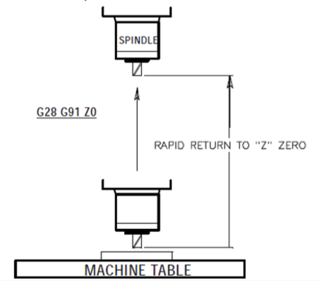
G28 Return To Reference Point, set optional intermediate point The G28 code is used to return to the machine zero position on all axes. If an X, Y, Z, or A axis is on the same block and specifies a location, only those axes will move and return to the machines‟ zero reference point and the movement to the machines„ zero reference point will be through that specified location.
Format: -G91 G28 X0 Y0 Z0;
G00 Rapid traverse
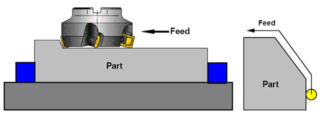
When the tool being positioned at a point preparatory to a cutting motion, to save time it is moved along a straight line at Rapid traverse, at a fixed traverse rate which is pre-programmed into the machine's control system. Typical rapid traverse rates are 10 to 25 m /min., but can be as high as 80 m/min.
Format
N_ G00 X__ Y__Z__

G01 Linear interpolation (feed traverse)
The tool moves along a straight line in one or two axis simultaneously at a programmed linear speed, the feed rate.
Format N__ G01 X__ Y__Z__ F__
G02/03 Circular interpolation
G02 moves along a CW arc
G03 moves along a CCW arc

Using Arc Centre:
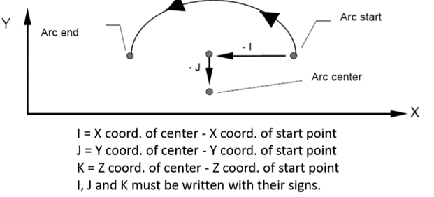
The arc center is specified by addresses I, J and K. I, J and K are the X, Y and Z co-ordinates of the arc center with reference to the arc start point.
Format N__ G02/03 X__ Y__Z__ I__ J__K__ F__
Using Arc Radius:
The radius is specified with address R.

FORMAT N__ G02/03 X__ Y__Z__ R__ F__
G04 Dwell
Format: G04X_; or G04F_; or G04P_;
X: Specified time(decimal point is permitted)
F: Specified time(decimal point is permitted)
P: Specified time(decimal point is unpermitted)
Explanation:G04 command dwell. The execution of the next block is delayed by the specified time, specify dwell for each rotation in feed per rotation mode. Dwell is use to stop feed for specified period of time.
Example: G04 X15 ,G04 F15, G04 P15000
Here M/C will Dwell for 15 second. The function Not modal. It can be used in Boring, Making CAM Profile, at these point dwell is required.
G15/G16 Commands of polar coordinate
The value can be inputted in the form of the polar coordinates (radius and angle ) The angle is position when the first axis of the selected plane is anticlockwise, and negative when it is clockwise.
G16;Start the command of polar coordinates (polar coordinates mode)
G15 ;Cancel the order of polar coordinate.
G17/G18/G19 Selection of planes
Use the parameters to appoint the circumrotate axis is X Y or Z ,or the axis that parallel to these axis , specify the G code to select the plane , to this plane , the circumrotate axis is the appointed line axis. For example, when the circumrotate axis is the axis that parallel to the X axis ,G17 should specify the plane of X and –Y, and only circumrotate axis one can be set.
When we omit the address of the axis of X Y and Z , we consider the third axis’s address is omitted
In the program, which are not appointed by the order of G17 G18 G19,the plane stay the same.
Inch/metric command change; G20, G21
G20 : Inch command
G21 : Metric command
G20 and G21 selection is meaningful only for linear axes and it is meaningless for rotary axes. The input unit for G20 and G21 will not change just by changing the command unit.
Tool and Geometry Compensation
Tool Length Compensation
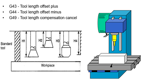
Different tools of different lengths are used in machining any part. The lengths of the tools are not considered in the part program. They are entered in the machine’s memory, and are considered automatically for each motion in the program depending on the tool that is being used. The tool lengths in the Z direction are called the Tool length offsets.
Codes Function
G43 Make the value of the cutter’s offset add to the value of Z coordinates of the program
G44 Make the value of the cutter’s offset subtract the value of Z coordinates of the Program
G49 Cancel the offset of the length of the cutter
The procedure of mentioning the difference of length of tool assumed during programming and actual tool used for machining is called tool length compensation
1) If the actual tool length is more than the assumed tool, the difference should be mentioned as follows
G43 H01
H01 – here 01 specifies the address where the difference of tool will be mentioned
2) If the actual tool length is less than the assumed tool, the difference should be mentioned as follows
G44 H01
H01 – here 01 specifies the address where the difference of tool will be mentioned.
Cutter Radius Compensation
When the Endmill cutter of some specified diameter is commanded to position at a location, actually the centre point of the cutter only coincide with the addressed point of the work piece.
So, it is necessary to shift the cutter for a radius amount towards left or right from the position. The procedure of shifting the tool of radius amount is called as Cutter Radius Compensation
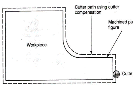
G41 - Cutter radius compensation left
G42 - Cutter radius compensation right
G40 - Cutter radius compensation cancel
The type of compensation is selected from the starting point as follows
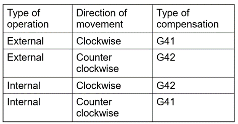
G41 - Cutter radius compensation left
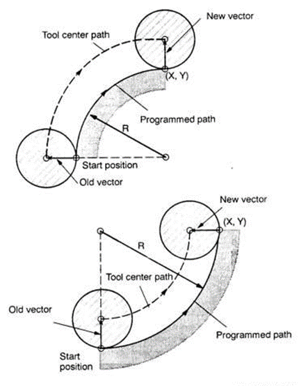
G41 D07;
Here, D specifies the address of offset at which the radius of tool will be mentioned
G42 - Cutter radius compensation right
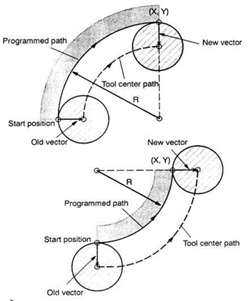
G41 D07;
Here, D specifies the address of offset at which the radius of tool will be mentioned
Subroutine
A subprogram is a separate program called up by another program. The use of subprograms can significantly reduce the amount of programming on some parts. Subroutines allow the CNC programmer to define a series of commands which might be repeated several times in a program and, instead of repeating them many times, they can be “called up” when needed. A subroutine call is done with M98 and a P. The P code command identifies the O program number being used when executed with M98
M99: -An M99 ends a sub-program and returns back to the next line in the main program after the M98 sub-program call.
Layout of CNC Program

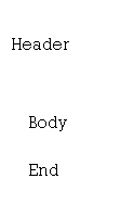 [BILLET X 25.0 Z 60.0; [Size of raw Material
G99 G21 S500 M13; [ Setting Cutting Condition
G28 U0 W0; [ Ref. Point Return
M06 T0101; [ Tool Call
 G00 X 25.0 Z 2.0; [Positioning
…… [ Path Definition
…… or Cycle Utility or Subroutine Utility
 G28 U 0 W0; [ Return to Ref. Point
M30; M30; [ End of Program
Linear Interpolation
It is achieved by linear path functions
G00 Rapid Linear Movement
G01 Linear Movement with Programmed Feed Rate
Writing Format
G00 X 50.0 Z2.0;
G01 X 50.0 Z2.0 F0.1;
Example Program
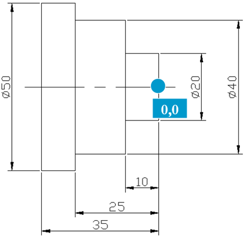
[BILLET X55.0 Z40.0;
G99 G21 G40;
S1000 M13;
M06 T0101;
G00 X55.0 Z2.0;
G01 X55.0 Z0.0 F0.2;
G01 X -1.0 Z0.0 F0.1;
G00 X 55.0 Z2.0;
G00 X20.0;
G01 X20.0 Z-10.0 F0.1;
G01 X40.0 Z-10.0;
G01 X40.0 Z-25.0;
G01 X50.0 Z-25.0;
G01 X50.0 Z-35.0;
G01 X55.0 Z-35.0;
G00 X55.0 Z2.0;
G28 U0 W0;
M30;
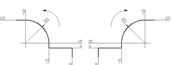
Circular Interpolation
It is achieved by using circular path function
Circular Path Function
G02 Circular Movement Clockwise (CW)
G03 Circular Movement Counter Clock
Writing Format
G02 X 25.0 Z-10.0 R5.0 F0.1;
G03 X 25.0 Z-10.0 R5.0 F0.1;
Example Program
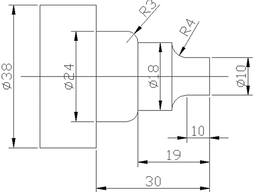
[BILLET X55.0 Z40.0;
G99 G21 G40 S1000 M13;
M06 T0101;
G00 X38.0 Z2.0;
G01 X38.0 Z0.0 F0.2;
G01 X -1.0 Z0.0 F0.1;
G00 X 38.0 Z2.0;
G00 X10.0;
G01 X10.0 Z-10.0 F0.1;
G02 X18.0 Z-14.0 R4.0;
G01 X18.0 Z-19.0;
G03 X24.0 Z-22.0 R3.0;
G01 X24.0 Z-30.0;
G01 X38.0 Z-30.0;
G00 X38.0 Z2.0;
G28 U0 W0;
M30;
Canned Cycle for Turning
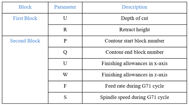
G71 turning cycle is used for rough-material removal from a CNC lathe component. G71 turning cycle makes large diameter cutting easy. Cutting can be done in simple straight line or a complex contour can also be machined very easily.
Through G71 turning cycle parameters CNC machinists can control
G71 turning cycle cuts the whole contour repeatedly which is given in PQ blocks.
Depth of every cut can be controlled by first-block U value.
Second-block U W are the finishing allowances which can be given if you want to make a finish cut with G70 finishing cycle.
F is cutting feed and S is spindle speed (given in second-block) which are used during G71 turning cycle.
The F and S given inside P Q block will not be used during G71 turning cycle, they are used with G70 finishing cycle if later called.
Programming syntax:
G71 U… R…
G71 P… Q… U… W… F… S…
G71 Turning Cycle Working:
N60 G71 U10 R10
N70 G71 P80 Q90 U3 W0 F0.25
N80 G00 X60
N90 G01 Z-75
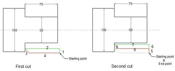
When G71 turning cycle is run the whole operation will be done in following sequence,
First-cut
1 – Tool will move in x-axis U (depth of cut) deep with programmed feed from starting point.
2 – Tool will travel with feed in z-axis (destination point in z-axis is given in P Q blocks)
3 – Tool rapidly retracts R amount in both x-axis and z-axis (at 45 degrees).
4 – Tool rapidly travel in z-axis to start-point
Later-cut
5 – Tool rapidly moves to last cut depth.
6 – Tool moves with feed in x-axis U deep (first-block U depth of cut).
7 – Tool with feed moves in z-axis (destination point given in P Q blocks).
8 – Tool rapidly retracts in x-axis and z-axis R amount (45 degrees).
9 – Tool rapidly moves to start-point only in z-axis.
Canned Cycle for facing
G72 cycle is used for facing operation.
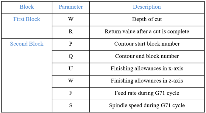
Programming syntax:
G72 W… R…
G72 P… Q… U… W… F… S…
G72 Facing Cycle Example:
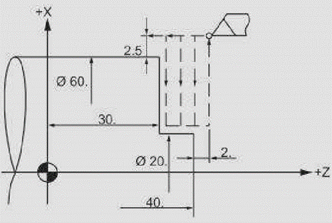
N5 G00 X65 Z42
N6 G72 W2 R2
N7 G72 P8 Q9 U0 W0 F0.3
N8 G00 Z30
N9 G01 X20
4.2.4 Canned Cycle for Grooving
G75 cycle is used for grooving
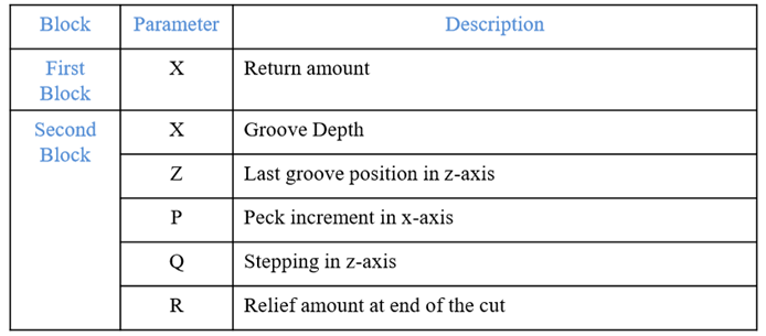
Programming syntax :
G75 X…
G75 X… Z… P… Q… R…
G75 Canned Cycle Grooving CNC Programming Example
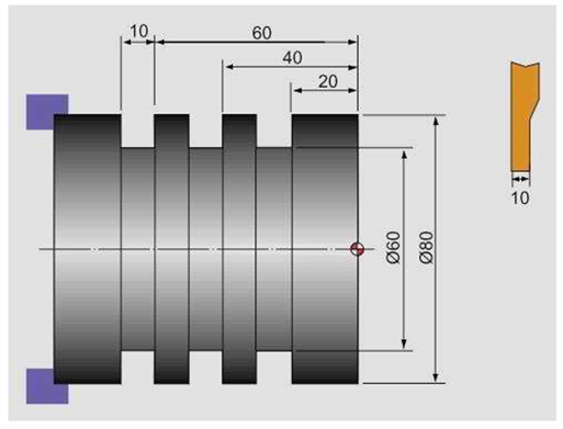
N10 G50 S500 T0100
N20 G97 S400 M03
N30 G00 X90.0 Z1.0 T0101
N40 G00 X82.0 Z-60.0
N50 G75 R1.0
N60 G75 X60.0 Z-20.0 P3000 Q20000 F0.1
N70 G00 X90.0
N80 G00 X200.0 Z200.0 T0100
N90 M30
Canned Cycle for Threading
G76 canned cycle is used for threading
Programming syntax:
G76 P010060 Q100 R0.05
G76 X30 Z-20 P1024 Q200 F2 R...


G76 Thread Cycle Example:
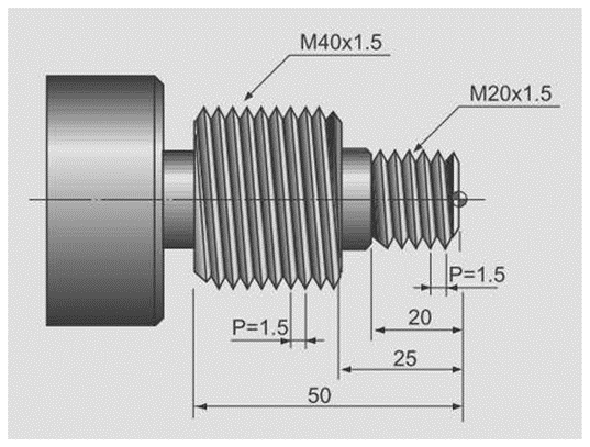
N10 T3
N20 G97 S800 M03
N30 G00 X30 Z5 T0303
N40 G76 P021060 Q100 R100
N50 G76 X18.2 Z-20 P900 Q200 F1.5
N60 G00 X50 Z-20
N70 G76 P021060 Q100 R100
N80 G76 X38.2 Z-52 P900 Q200 FI .5
N90 G00 X200 Z200
N100 M30
4.5.1 CNC Part Program Syntax
CNC Program can be divided into three parts.
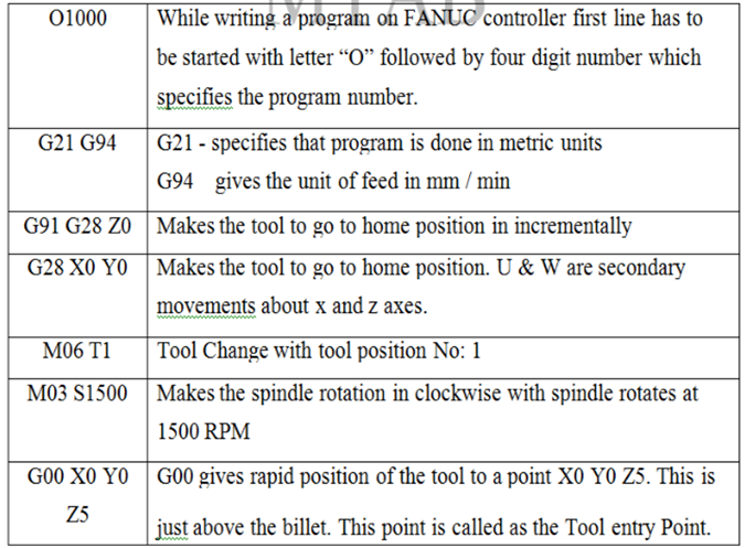
1. Start-up Program
O1000
G21 G24
G91 G28 Z0
G28 X0 Y0
M06 T1
M03 S1500
G00 X0 Y0 Z5
2. Profile Program
Profile program is based on the given part drawing.
3. End of the Program
G91 G28 Z0
G28 X0 Y0
M05
M30

4.5.2 Linear and Circular interpolation
Similar in CNC lathe part programming,
Linear Interpolation is achieved by linear path functions
G00 Rapid Linear Movement
G01 Linear Movement with Programmed Feed Rate
Writing Format
G00 X 50.0 Z2.0;
G01 X 50.0 Z2.0 F0.1;
AND
Circular Interpolation is achieved by using circular path function
Circular Path Function
G02 Circular Movement Clockwise (CW)
G03 Circular Movement Counter Clock
Writing Format
G02 X 25.0 Z-10.0 R5.0 F0.1;
G03 X 25.0 Z-10.0 R5.0 F0.1;
Example for Linear and circular interpolation

O1001
G21 G94
G90 G28 Z0
G28 X0 Y0
M06 T1
M03 S1500
G90 G00 X-30 Y-20 Z5
G01 Z-1 F100 G01 X-30 Y20
G02 X-20 Y30 R10
G01 X20 Y30
G03 X30 Y20 R10
G01 X30 Y-20
G01 X20 Y-30
G01 X-20 Y-30
G03 X-30 Y-20 R10
G00 Z5
G91 G28 Z0
G28 X0 Y0
M05
M30
4.5.3 Canned Cycle for Drilling
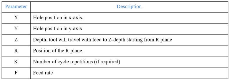
G81 canned cycle is used for drilling
Programming syntax :
G81 X... Y... Z... R... K... F...
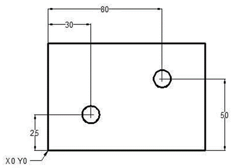
Working Example:
N10 T1 M06
N20 G90 G54 G00 X30 Y25
N30 S1200 M03
N40 G43 H01 Z5 M08
N50 G81 Z-10 R2 F75
N60 X80 Y50
N70 G80 G00 Z100 M09
N80 M30
4.5.4 Canned Cycle for pocketing
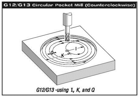
There are two G codes, G12 and G13 that will provide for pocket milling of a circular shape. They're different only in which direction of rotation is used. G12 and G13 are non-modal.
G12 Circular Pocket Milling Clockwise
Program Syntax:
G12 X_Y_Z_ I_K_Q_L_ D*_F_
Parameters
X Position in X axis to center of circular pocket
Y Position in Y axis to center of circular pocket
Z Z depth of cut, or it's the increment depth of cuts when used with G91 I Radius Of First Circle (Or it's the finish radius if K is not used)
K Radius Of Finished Circle (If specified)
Q Radius cut increment step-over of the spiral out (Q is used with K only)
L Loop count for repeating incremental depth of cuts (L is used with G91)
D* Cutter Comp. Offset Number (Enter cutter size in offset display register)
F Feed Rate in inches (mm) per minute This G12 code implies the use of G42 cutter compensation right
G13 Circular Pocket Milling Counterclockwise
This G13 code implies the use of G41 cutter compensation left and will be machining in a counterclockwise direction, but is otherwise the same as G12. G13 is usually preferred instead of G12, since G13 will be climb cutting when used with a standard right handed tool.
References:
1. Ibraim Zeid, Mastering CAD/CAM – Tata McGraw Hill Publishing Co. 2000
2. Segerling L. J. - Applied Finite Elements Analysis, John Wiley and Sons
3. Seshu P. Text book of Finite Element Analysis, PHI Learning Private Ltd. New Delhi, 2010
4. Rao P. N., Introduction to CAD/CAM Tata McGraw Hill Publishing Co.
5. B. S. Pabla, M. Adithan, CNC Machines, New Age International, 1994
6. Groover M.P.-Automation, production systems and computer integrated manufacturing‘ - Prentice Hall of India
7. Ian Gibson, David W. Rosen, Brent Stucker, Additive Manufacturing Technologies: Rapid Prototyping to Direct Digital Manufacturing, Springer
8. Geoffrey Boothroyd, Peter Dewhurst, Winston A. Knight, Product Design for Manufacture and Assembly, Third Edition ,CRC Press
9. Antti Saaksvuori, Anselmi Immonen, Product Life Cycle Management -Springer, 1st Edition, 2003