Unit 5
Advanced Manufacturing Method
Product life cycle Management (PLM) is a system of managing the entire life cycle of the product.
Product lifecycle management (PLM) is the Business Strategy of managing the entire lifecycle of a product from its conception, through design and manufacture, to service and disposal.
It Supports the Extended enterprise (Customers, Design and supply partners). PLM Spans from the Concept to the last stage – the life of a product or plant.
The life cycle of the product includes:
Need of PLM
Components / Elements of PLM
The following are the essential elements of PLM:
The document management component stores, tracks and manages all the data associated with product and product development process.
2. CAD/CAM Data management
This component enables complete management and control of CAD/CAM data from all CAD/CAM tools used in organization.
It is very important in design and manufacturing of product.
3. Project Task (Workflow) management
This component assists in establishing and standardizing the product development process.
4. BOM (Bill of Materials) management
This component of PLM system stores and manages vast data about BOM. It helps to assess the potential impact of any change of materials on product cost.
5. Collaboration management
Collaboration management ensures all internal as well as external partners can work concurrently on project with full data protection.
6. Confirmation and change management
This component makes sure that every stake holder of system is aware of each process and updated changes of in all phases of product lifecycle from inception to disposal.
Collaborative Engineering
“Collaborative engineering is defined for the study of interactive process of engineering collaboration wherein, in order for serving their mutual interests, multiple interested stakeholders or partners:
i) Resolve conflicts
ii) Bargain for individual or group advantages
iii) Agree upon course of action
iv) Attempt to achieve joint outcomes
The aim of collaborative engineering is to facilitate the individuals and organizations, across the boundaries of discipline, geography and culture, to work effectively with collaborative actions for achieving joint outcomes.
It is used most effectively in product design, manufacturing, construction, etc.
Fundamentals of Rapid Prototyping
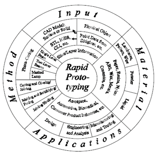
The Rapid Prototyping Wheel depicting the 4 major aspects of RP
2. Method
While they are currently more than 20 vendors for RP systems, the method employed by each vendor can be generally classified into the following categories:
• photo-curing,
• cutting and gluing/joining,
• melting and solidifying/fusing and joining/binding.
Photo-curing can be further divided into categories of
• single laser beam,
• double laser beams and
• masked lamp
3. Material
4. Application
Basic Steps in Rapid Prototyping Process
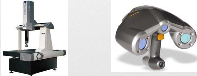
2. Conversion to STL Format:
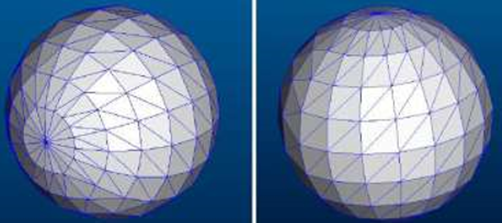
3. Slice the STL File:
4. Layer by Layer Construction:
5. Clean and Finish:
Based on initial form of material used, the rapid prototyping systems are broadly classified into three categories.
a) Stereolithography (SLA)
b) Polyjet Modelling
2. SOLID-BASED
a) Fused Deposition Modelling (FDM)
b) Laminated Object Modelling (LOM)
3. POWDER-BASED
a) Selective Laser Sintering (SLS)
b) 3D- Printing
Stereolithography (SLA)
Working Principle
SLA uses a low-power, highly focused UV laser to produce a three-dimensional object in a vat of liquid photosensitive polymer.
Features
Material type: Liquid(Photopolymer)
Materials: Thermoplastics(Elastomers)
Min layer thickness: 0.02 mm
Surface finish: Smooth
Build speed: Average
Model and specification of process
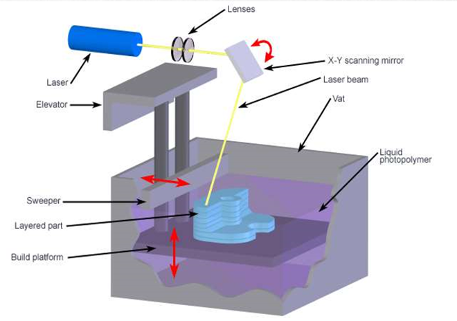
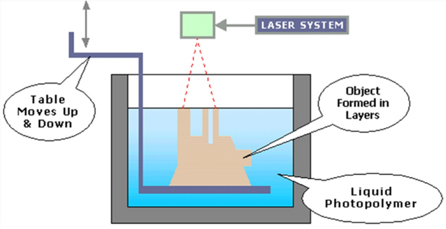
SLA Process
Working
ADVANTAGES
DISADVANTAGES
Application
Fused Deposition Modelling
Working Principle
A plastic or wax material is extruded through a nozzle that traces the part´s cross sectional geometry layer by layer
Features
Material type: Solid(Filaments)
Materials: ABS, Polycarbonate, Poly phenyl-sulfonite;Elastomers
Min layer thickness: 0.15mm
Surface finish: Rough
Build speed: Slow
Model and specification of process
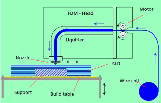
FDM Process
Working
Advantages
Disadvantages
Application
Laminated Object manufacturing (LOM)
Working Principle
The build material is placed on a platform and a heated roller bonds it to the previous layer and the sheet is cut to required profile by laser and glued to previous sheet.
Features
Material type: Solid(Sheets)
Materials: Thermoplasticssuchas PVC; Paper; Composites(Ferrousmetals; Non-ferrousmetals; Ceramics)
Min layer thickness: 0.05mm
Surface finish: Rough
Build speed: Fast
Model and specification of process
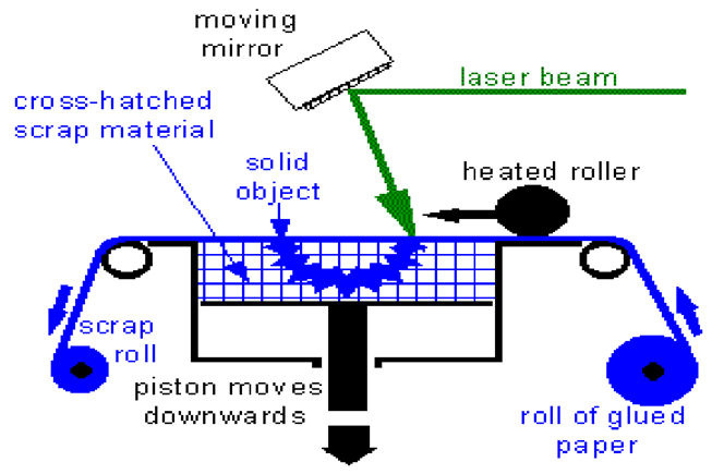
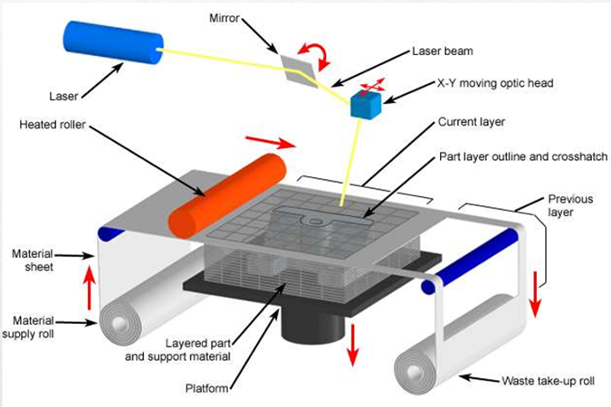
LOM Process
Working
Advantages
Disadvantages
Application
Selective Laser Sintering
Principle of Working
It uses a moving laser beam to trace and selectively sinter powdered polymer and/or metal composite materials.
Features
Material type: Powder(Polymer)
Materials: Thermoplastics: Nylon, Polyamide and Polystyrene; Elastomers; Composites
Min layer thickness: 0.10mm
Surface finish: Average
Build speed: Fast
Model and specification of process
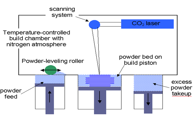
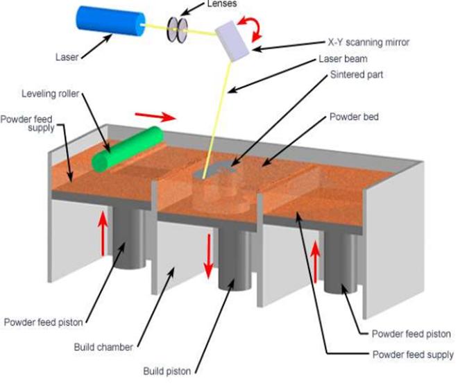
SLS Process
Working
Advantages
Disadvantages
Applications
3D Printing
Principle
An ink-jet printing head deposits a liquid adhesive that binds the starch powder material.
Features
Material type: Powder
Materials: Ferrousmetalssuchas Stainlesssteel; Non-ferrousmetalssuchas Bronze; Elastomers; Composites; Ceramics
Min layer thickness: 0,05mm
Surface finish: Rough
Build speed: VeryFast
Model and specification of process
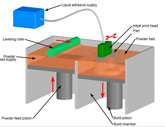
3D Printing
Working
Advantages
Disadvantages
Applications
Rapid-prototyping techniques have made possible much faster product development times, and they are having a major effect on other manufacturing processes. When appropriate materials are used, rapid-prototyping machinery can produce blanks for investment casting or similar processes, so that metallic parts can now be obtained quickly and inexpensively, even for lot sizes as small as one part.
Such technologies also can be applied to producing molds for operations (such as injection molding, sand and shell mold casting, and even forging), thereby significantly reducing the lead time between design and manufacture.
Several methods have been devised for the rapid production of tooling (RT) by means of rapid-prototyping processes.
The advantages to rapid tooling include the following:
The main shortcoming of rapid tooling is the potentially reduced tool or pattern life (compared to those obtained from machined tool and die materials, such as tool steels or tungsten carbides).
The simplest method of applying rapid-prototyping operations to other manufacturing processes is in the direct production of patterns or molds.
Conventional Tooling vs Rapid Tooling:
RT is distinguished from conventional tooling in that,
Need of Rapid Tooling (RT)
Advantages of RT
STL File Format
What is STL File?
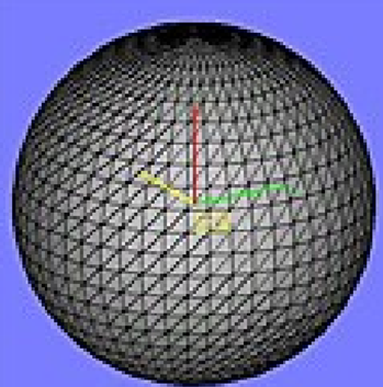
STL File Format
There are two formats of STL File:
3D printed materials can be more flexible and useful, the structures of the material can transform in a pre-programmed way in response to any external stimulus. In general, self-changing structure of 3D printed part after post process is called 4D printing process.
In 4D printing process, 1D strand or 2D surface having multi-material feature, is created using the same 3D printing techniques.
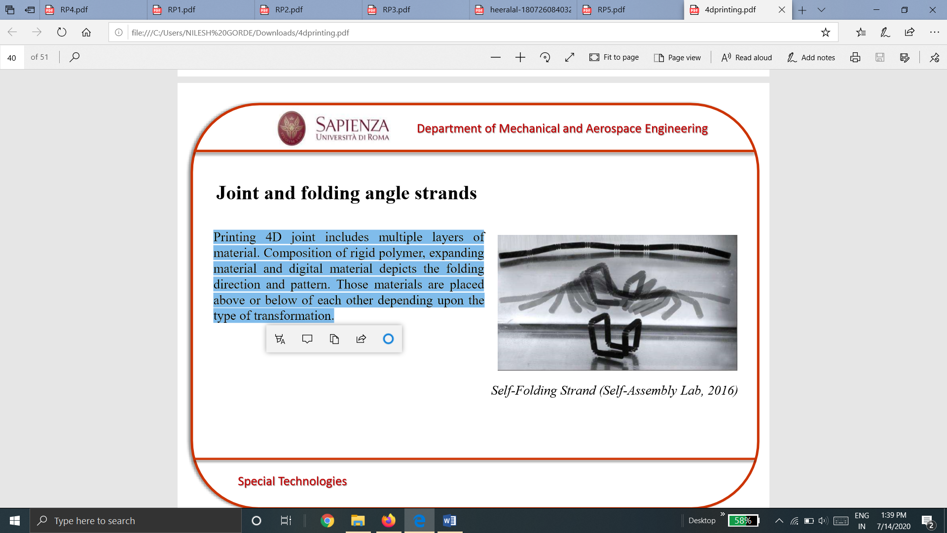
Joint and folding angle strands
Printing 4D joint includes multiple layers of material. Composition of rigid polymer, expanding material and digital material depicts the folding direction and pattern. Those materials are placed above or below of each other depending upon the type of transformation.
Custom Angle Surfaces
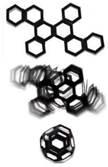
Similar mechanism as folding strand described previously, series of flat two-dimensional structures were generated with edge joints. The position and spacing of materials at each joint specifies the desired fold angle hence positioned accordingly.
4D printed self-folding truncated octahedron demonstrating the “transformation over time” when submerging in water.
References
1. Ibraim Zeid, Mastering CAD/CAM – Tata McGraw Hill Publishing Co. 2000
2. Segerling L. J. - Applied Finite Elements Analysis, John Wiley and Sons
3. Seshu P. Text book of Finite Element Analysis, PHI Learning Private Ltd. New Delhi, 2010
4. Rao P. N., Introduction to CAD/CAM Tata McGraw Hill Publishing Co.
5. B. S. Pabla, M. Adithan, CNC Machines, New Age International, 1994
6. Groover M.P.-Automation, production systems and computer integrated manufacturing‘ - Prentice Hall of India
7. Ian Gibson, David W. Rosen, Brent Stucker, Additive Manufacturing Technologies: Rapid Prototyping to Direct Digital Manufacturing, Springer
8. Geoffrey Boothroyd, Peter Dewhurst, Winston A. Knight, Product Design for Manufacture and Assembly, Third Edition ,CRC Press
9. Antti Saaksvuori, Anselmi Immonen, Product Life Cycle Management -Springer, 1st Edition, 2003