Unit 6
AUTOMATION
Automation can be explained as a process to create, control and monitor the applications of technology. Automation is the process of handling the operation of equipment such as processors, machinery, stabilization of ships, aircraft, boilers and many applications with minimum human efforts.
NEED OR REASONS FOR AUTOMATION
Automation Strategies
First strategy in automation is to look for simple solutions and avoid complex solutions. Simple solutions are cost effective, easy for operations, and easy for maintenance.
2. Specialization of operations
Special purpose machine should be developed for performing one operation with maximum possible efficiency.
3. Multiple operations
Multiple operation should be done at one machine or workstation. This reduces the number of machines required.
4. Simultaneous operation
Multiple operations should be carried out simultaneously. This reduces machining time.
5. Integration of Workstations
Many workstations should be integrated into a single integrated mechanism using automated work handling devices. This reduces work handling time.
6. Increased flexibility
A workstation should have flexibility to machine different products. This helps in maximum utilization of machine.
7. Automated material handling and storage systems
Non-production time can be reduced using automated material handling and storage systems.
8. On-line Inspection
In-process correction is achieved due to on-line inspection. This reduces scrap and improves quality of product.
9. On-line monitoring, Process Control and Optimization
On-line monitoring and process control helps in taking the corrective actions in case of deviation.
10. Control of Plant Operations
All the plants are networked using computers so that all the plant can be controlled and monitored at one place.
11. Computer Integrated manufacturing (CIM)
CIM integrates manufacturing operations and manufacturing support systems. CIM is complete integration of factory using computer network.
Types of Automation
Three main classification are:
“Fixed automation is an automation system in which the sequence of operation is fixed by the layout of production equipment.”

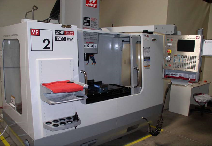
2. Programmable Automation:
“Programmable automation is the automation system in which the production equipments are designed with a capability to change the sequence of operations so as to accommodate the different product configuration.”
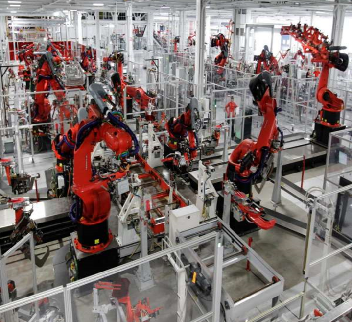
3. Flexible (soft) Automation:
“Flexible Automation is an automation system capable of producing products of design variation, continuously with little or no time loss for changeovers of one product to another.”
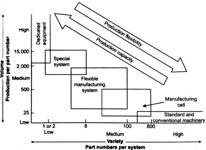
FMS may be defined as “a highly automated GT machine cell, consisting of a group of processing workstations (usually CNC machine tools), interconnected by an automated material handling and storage system, and controlled by a distributed computersystem.”
FMS employs a fully integrated handling systemwith automated processing stations.
Need of FMS
Application of FMS
Advantages of FMS
Limitation of FMS
Types of FMS
Classification based on the kinds of operations they perform
Classification based on the number of machines in the system
Classification based on the level of flexibility associated with the system
A] Classification based on the kinds of operations they perform
Processing operation
Assembly operation
B] Classification based on the number of machines in the system
Single Machine Cell (SMC)
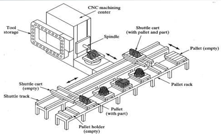
SMC consists of one workstation, one material handling system and one computer control system.
Flexible machine cell (FMC)
FMC consists of two or three workstation, material handling and storage system and computer control system.
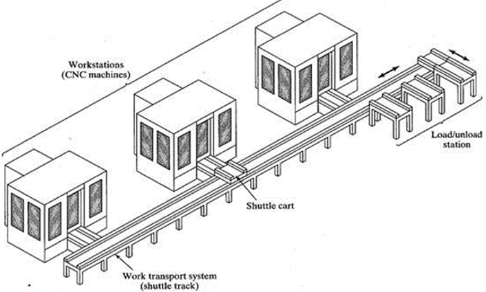
Flexible manufacturing system (FMS)
FMS consists of four or more workstation, one material handling and storage system and only one computer control system. The computer control system in FMS is generally larger and more sophisticated than SMC and FMC.
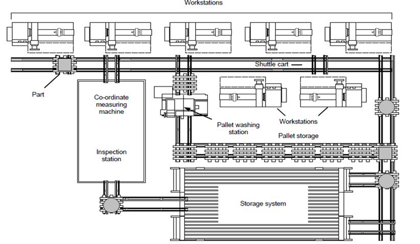
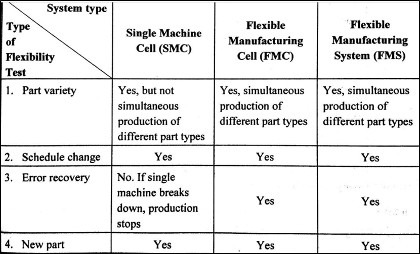
C] Classification based on the level of flexibility associated with the system
Dedicated FMS
Random order FMS
Automated Guided Vehicle System (AGVS)
Types of AGVs
The Guided driverless trains, also known as towing vehicles or automated guided tractors, are most commonly used for transporting large amount of bulky and heavy materials from thewarehousetovariouslocationsinthemanufacturingplant.
2. Guided Pallet Trucks
The guided pallet trucks are designed to lift and transport palletized loads. It is used for picking up or dropping off loads from and on to floor level. Thus, it eliminates the need for fixed load stands.
3. Guided unit load carriers
Guided unit load carriers have a deck that permits unit-load transportoperation. They are used in settings with short/medium guide paths, high volume,and need for independent and versatility.They can operate in an environment where there is not much roomandmovementisrestricted.
Application of AGV
Automated Guided Vehicles are used in a variety of areas to support processing and handling throughout a manufacturing facility.
Automated Storage and Retrieval System
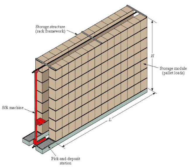
It consists of a variety of computer-controlled systems for automatically placing and retrieving loads from defined storage locations.
Basic structure of AS/RS
2. Storage/Retrieval Machine
3. Storage Modules
4. Pickup and Deposit (P/D) Stations
5. External handling system
Part Family
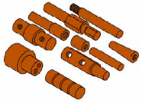
Ten parts that are different in size and shape, but quite similar in terms of manufacturing. All parts are machined from cylindrical stock by turning; some parts require drilling and/or milling.
Coding Methods in Group Technology
Coding refers to the process of assigning symbols to the parts.The symbols represent design attributes of parts or manufacturing features of part families.
The variations in codes resulting from the way the symbols are assigned can be grouped into three distinct type of codes:
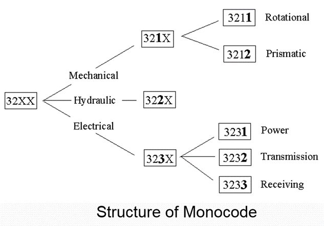
The structure of Monocode is like a tree in which each symbol amplifies the information provided in the previous digit.
A monocode (hierarchical code) provides a large amount of information in a relatively small number of digits.
Useful for storage and retrieval of design related information such as part geometry, material, size, etc.
2. Poly Code
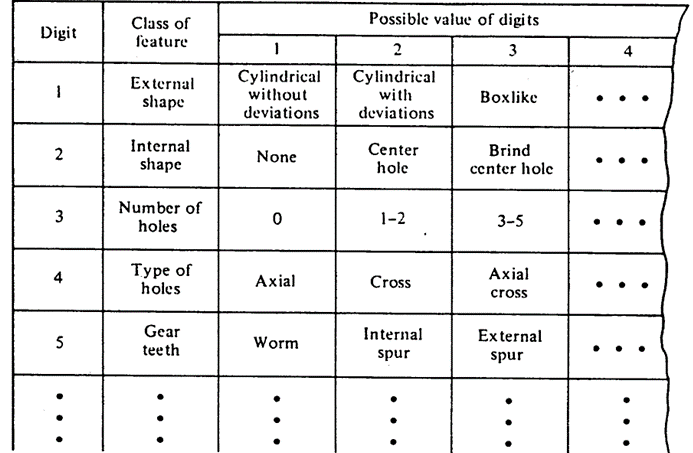
Chain-type structure, known as a polycode, in which the interpretation of each symbol in the sequence is always the same; it does not depend on the value of preceding symbols, so symbols are independent of each other.
Each digit in specific location of the code describes a unique property of the workpiece. It is easy to learn and useful in manufacturing situations where the manufacturing process have to be described.
The length of a Polycode may become excessive because of its unlimited combinational features.
3. Hybrid Code
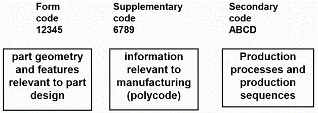
It is the mixture of both monocode and polycode systems. Mixed code retains the advantages of both systems. Most coding systems use this code structure.
Example - OPTIZ Classification System:
OPTIZ Classification System
Computer Integrated Manufacturing
CIM is the integration of the total manufacturing enterprise through the use of integrated systems and data communications coupled with new managerial philosophies that improve organizational and personnel efficiency.
The term CIM comprises three words – computer, integrated and manufacturing. CIM is the application of computers in manufacturing in an integrated way.CIM is an attempt to combine computer technologies in order to manage and control the entire business and manufacturing.
CIM is the computerization of design, manufacturing, distribution and financial/business function into one coherent system
There are four Islands of Automation in CIM:
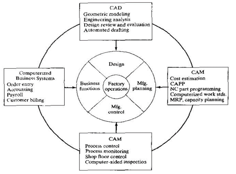
Objectives of CIM:
Computer-aided process planning (CAPP) is the application of the computer to assist process planners in the planning functions. It is considered as the key technology for computer-aided design (CAD) and computer aided manufacturing (CAM) integration.
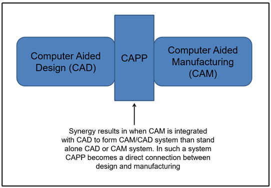
Methods of CAPP
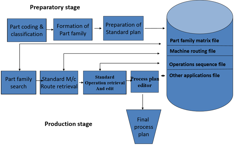
There are two main methods in CAPP
The variant process planning approach can be realized as a four step process
2. Generative process planning
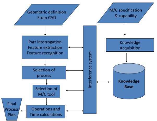
It is the system which creates plan by means of decision logic, formulas,geometry-based data and other logical procedures.
In this method process plans are prepared without the assistance of human and predefined plans. After retrieving this information, the system can generate the required processes and process sequences for the work part.There are two main components of generative process planning
Geometry description and coding component:
Process knowledge database & decision-making logic:
Advantages of CAPP
Robot:
Robot is defined as, “A reprogrammable and multifunction machine designed to move materials, tools or specialized instruments, by programmed movements to carry out a variety of tasks.”
Robot Characteristics:
Basic Laws of Robotics:
There are three basic laws of robotics as follows:
Robot Anatomy
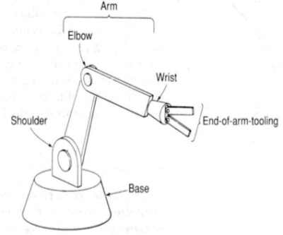
Robot anatomy consists of seven components:
Degree of Freedom
The degrees of freedom (dof) of a rigid body is defined as the number of independent movements it has.
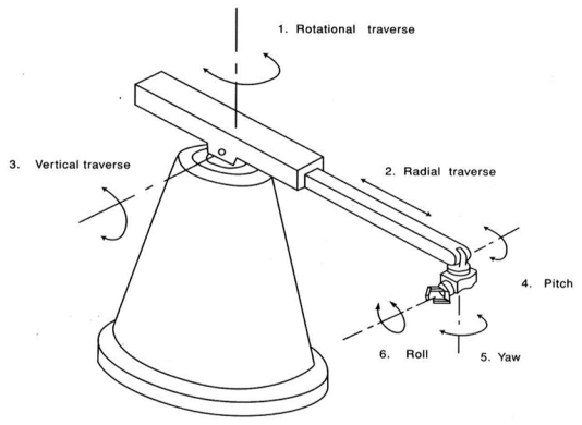
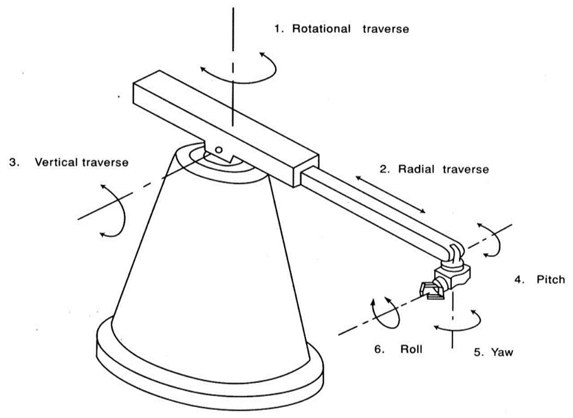
The three degrees of freedom located in the arm of a robotic system are:
The three degrees of freedom located in the wrist, which bear the names of aeronautical terms, are
Types of Robots
Based on technique used to control the motion of various axes of the robot, the robots are broadly classified into two categories:
In the non-servo-controlled robots, the axes of robot remain in non-controlled motion from initial point till the end stop.
The control of motion through sensors is only at start and end of the motion. There is no monitoring of motion at any intermediate points.
2. Servo-controlled robots:
In the non-servo-controlled robots, the axes of robot remain in controlled motion from initial point till the end stop.
The motion is monitored and controlled all the time from beginning till the end. The control system is closed-loop type.
The servo-controlled robots are further divided into two types
Point-to-point servo-controlled robots:
In point to point servo-controlled robot, the end effector moves from one point to another point in its work envelop along a straight line. The path of motion between the two points cannot be controlled. However, velocity and acceleration can be controlled.
It uses Stepper Motor
Such robots are normally used in loading-unloading and material handling.
Continuous path Servo-controlled robots:
In continuous path servo-controlled robot, the end effector moves along the predetermined continuous path of desired geometry. The motion of the path is continuously monitored and controlled.
It is most expensive of all control units. This robots are High-technology control unit They requires large memory capacity.
Such robots are used for spray painting, arc welding, polishing, grinding, etc.
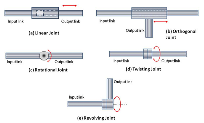
Joints
The manipulator of an industrial robot consists of a series of joints and links.A robotic joint provides relative motion between two links of the robot. Each joint, or axis, provides a certain degree-offreedom (dof) of motion. In most of the cases, only one degree-of-freedom is associated with each joint.Each joint is connected to two links, an input link and an output link. Joint provides controlled relative movement between the input link and output link.
Classification of Joint
a) Linear joint (type L joint)
The relative movement between the input link and the output link is a translational sliding motion, with the axes of the two links being parallel.
b) Orthogonal joint (type U joint)
This is also a translational sliding motion, but the input and output links are perpendicular to each other during the move.
c) Rotational joint (type R joint)
This type provides rotational relative motion, with the axis of rotation perpendicular to the axes of the input and output links.
d) Twisting joint (type T joint)
This joint also involves rotary motion, but the axis or rotation is parallel to the axes of the two links.
e) Revolving joint (type V-joint, V from the “v” in revolving)
In this type, axis of input link is parallel to the axis of rotation of the joint. However, the axis of the output link is perpendicular to the axis of rotation.
End effector is a device that attaches to the wrist of the robot arm and enables the general-purpose robot to perform a specific task.
It consists of:
There are four Major Types of gripper
1.Mechanical Gripper
2.Magnetised gripper
3.Pneumatic Gripper
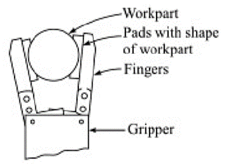
It is an end effector that uses mechanical fingers actuated by a mechanism to grasp an object.
Two ways of constraining part in gripper
1. Physical construction of parts within finger. Finger encloses the part to some extent and thereby designing the contact surface of finger to be in approximate shape of part geometry.
2. Holding the part is by friction between fingers and workpart. Finger must apply force that is sufficient for friction to retain the part against gravity.
To resist the slippage, the gripper must be designed to exert a force that depends on the weight of the part, coefficient of friction and acceleration of part.
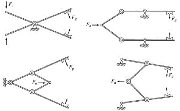
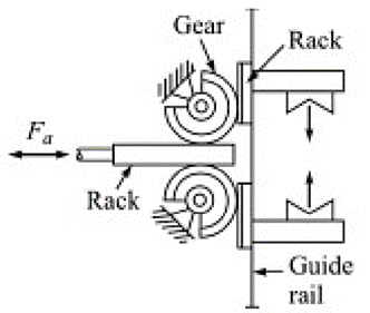
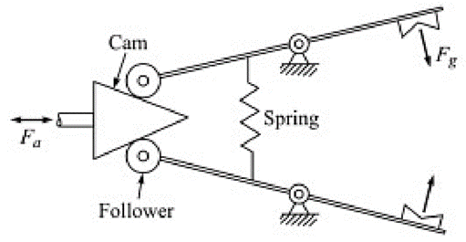
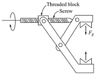
Four ways of gripper mechanism based on kinematic devices
1.Linkage actuation
2.Gear and rack actuation
3.Cam actuation
4.Screw actuation
2. Magnetic Gripper
Magnetic grippers are be divided into 2 types:
Electromagnetic grippers include a controller unit and a DC power for handling the materials. This type of grippers is easy to control, and very effective in releasing the part at the end of the operation than the permanent magnets. If the work part gripped is to be released, the polarity level is minimized by the controller unit before the electromagnet is turned off.
ii. Permanent magnetic Gripper:
The permanent magnets do not require any sort of external power as like the electromagnets for handling the materials. After this gripper grasps a work part, an additional device called as stripper push – off pin will be required to separate the work part from the magnet. This device is incorporated at the sides of the gripper.
This gripper only requires one surface to grasp the materials. The grasping of materials is done very quickly. It does not require separate designs for handling different size of materials. It is capable of grasping materials with holes, which is unfeasible in the vacuum grippers
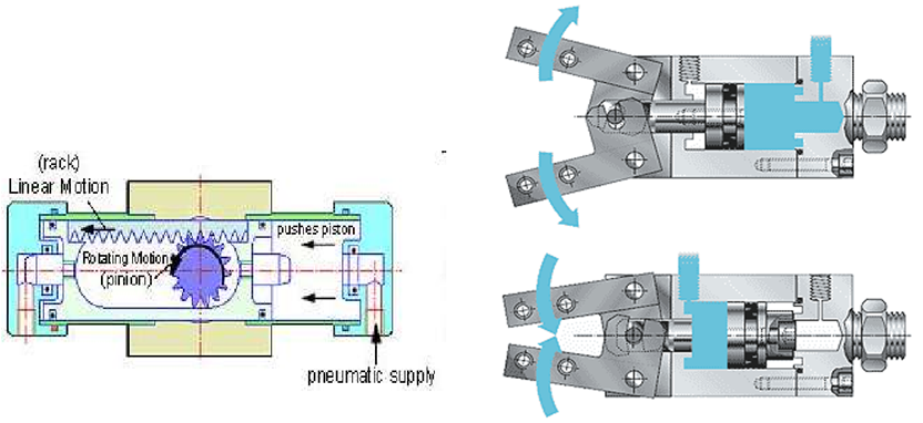
3. Pneumatic Gripper
Equipped with roller membrane cylinder with a rolling motion replacing conventional piston cylinder.
This motion is transmitted to fingers by means of lever mechanism.
The grippers are actuated by switching valves in the circuit.
The finger stroke is limited by end stops or workpiece to be gripped.
Robotics Application
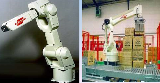
Robots is used in industries for applications like:
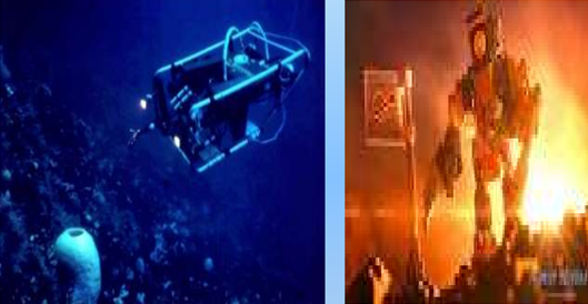
2. Robots in Hazardous environment
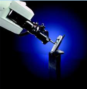
The hazardous environment can be defined as the place where human cannot survive and harmful. Some examples of hazardous environments are nuclear reactors, outside earth’s atmosphere and even behind enemy lines in war.
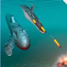
3. Military Application
Military robots, autonomous robots or remote-controlled mobile robots designed for military applications from transport to search & attack.
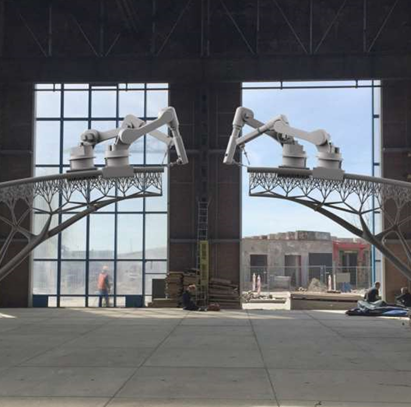
4. Construction application
The construction industry slightly depends on robot. Robots can reduce the breakneck phenomenon such as metal dissolve, piling etc.
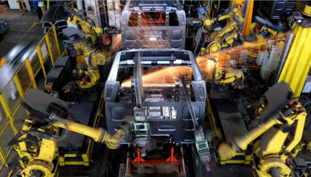
5. Automobiles application
Robotics are Advancing automobile manufacturing to new heights. Robots gives automotive companies a competitive advantage. It is mainlyused to improve quality and reduce warranty cost.
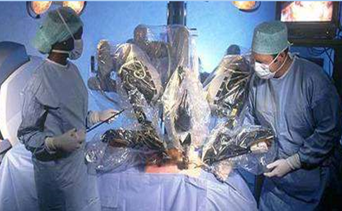
6. Medical Robot
A medical robot is a robot used in the medical science. They include, but are not limited to surgical robot.
7. Agricultural Robot
Agricultural robots is a robot deployed for agricultural purposes. The main area of application of robots in agriculture today is at the harvesting stage.
References
1. Ibraim Zeid, Mastering CAD/CAM – Tata McGraw Hill Publishing Co. 2000
2. Segerling L. J. - Applied Finite Elements Analysis, John Wiley and Sons
3. Seshu P. Text book of Finite Element Analysis, PHI Learning Private Ltd. New Delhi, 2010
4. Rao P. N., Introduction to CAD/CAM Tata McGraw Hill Publishing Co.
5. B. S. Pabla, M. Adithan, CNC Machines, New Age International, 1994
6. Groover M.P.-Automation, production systems and computer integrated manufacturing‘ - Prentice Hall of India
7. Ian Gibson, David W. Rosen, Brent Stucker, Additive Manufacturing Technologies: Rapid Prototyping to Direct Digital Manufacturing, Springer
8. Geoffrey Boothroyd, Peter Dewhurst, Winston A. Knight, Product Design for Manufacture and Assembly, Third Edition ,CRC Press
9. Antti Saaksvuori, Anselmi Immonen, Product Life Cycle Management -Springer, 1st Edition, 2003