Unit 1
Single Degree of Freedom Systems – Free Vibration
Introduction to vibration
Vibration:
“Any motion which repeats itself after an interval of time is called vibration.”
Eg: Swinging of simple pendulum
Causes of vibration:
Effect of Vibration
Produces unwanted noise, high stresses, wear, poor reliability and premature failure of one or more of the parts.
In spite of these harmful effects, it is used in musical instruments, vibrating conveyors etc.
Elimination of Vibrations
Elements of Vibratory System
Any vibratory system consists of three elements
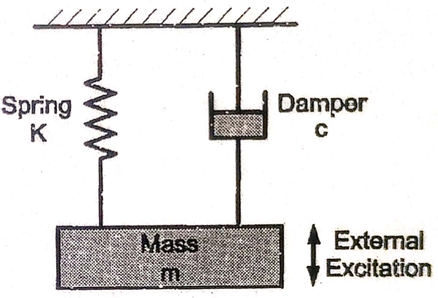
Fig. shows a basic vibratory system. The energy enters the system with the application of external force known as external excitation. Due to excitation mass is disturbed from its mean position and mass starts vibrating between two extreme positions. During this vibrations, potential energy and kinetic energy are converted into one another periodically. Hence, system continues to vibrate.
Now, if some damper is provided to oppose the motion of mass, then some amount of energy is dissipated in each cycle due to damping effect and system decays gradually.
Vector Representation of SHM and basic Terminologies
Simple Harmonic Motion:
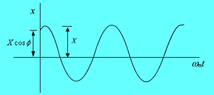
Simplest form of periodic motion is harmonic motion and it is called simple harmonic motion (SHM). It can be expressed as
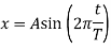
where A is the amplitude of motion, t is the time instant and T is the period of motion.
Harmonic motion is often represented by projection on line of a point that is moving on a circle at constant speed.
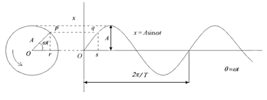
From fig we have,
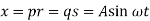
where x is the displacement and  is the circular frequency in rad/sec

where T is the period (sec) and is the frequency (cycle/sec) of the harmonic motion.
The SHM repeats itself in radians.
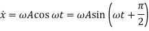
Displacement can be expressed as

So that the velocity and acceleration can be written as

Basic Terminologies
Frequency
Number of cycles per unit time.
Natural Frequency (fn)
Frequency of free vibration of the system.
Expressed in Hz or rad/sec.
Amplitude
The maximum displacement of a vibrating body from its equilibrium position.
Resonance
When the frequency of external excitation is equal to the natural frequency of a vibrating body, the amplitude of vibration becomes excessively large. This concept is known as resonance.
Periodic Motion
A motion which repeats itself after equal intervals of time.
Time Period
Time taken to complete one cycle.
Stiffness of spring (K)
It is the force required to produce unit displacement in the direction of applied force.

Where,
K = stiffness of spring, N/m
F = force applied on spring, N
 = deflection of spring, m
Damping
Damping is the resistance to the motion of the vibrating body, which causes a vibrating body to come to rest or equilibrium position.
Damping Coefficient (c)
Damping coefficient is the damping force or resisting force developed per unit velocity.
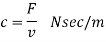
Where,
F = Force applied on damper or damping Force, N
v = Velocity of viscous fluid, m/sec
Fundamental mode of vibration
The fundamental mode of vibration of a system is the mode having the lowest natural frequency.
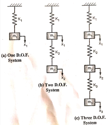
The minimum number of independent co-ordinates required to specify the motion of system at any instant is known as degrees of freedom.
It is equal to the number of independent displacements that are possible. This number varies from zero to infinity.
Zero degree of freedom
The body at rest is said to have zero degree of freedom.
Single Degree of freedom
Here there is only one independent co-ordinate to specify the configuration.
Eg: A mass supported by a spring.
Two degree of freedom
There are two independent co-ordinates to specify the configuration.
Eg: Springs supported Rigid mass. (It can move in the direction of springs and also have angular motion in one plane)
Multi degrees of freedom
A cantilever beam has infinite degrees of freedom.
Introduction to Physical and Mathematical modelling
Physical modelling is the process of making the actual prototype of an object by using the material like: wood, plastic or easy to work materials
Mathematical Model is the process of representing a system in terms of a set of equation.
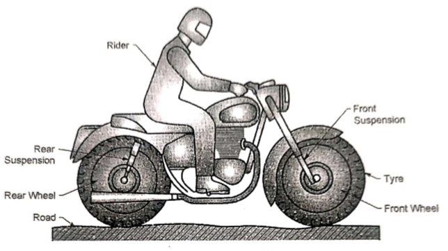
Fig (a) below shows the physical model of bicycle with rider.
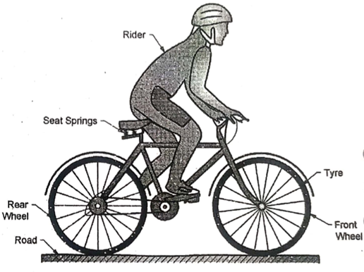
(a) Physical model of Bicycle
In order to develop a mathematical model of a physical system consisting of a bicycle and rider, following parameters are considered:
mr = mass of rider
Kr = Stiffness of rider
Cr = Damping coefficient of rider
mv = mass of bicycle (except wheels)
Ks1 = Stiffness of rear suspension
Ks2 = Stiffness of front suspension
Mw = mass of each wheel
Kt = Stiffness of each tyre
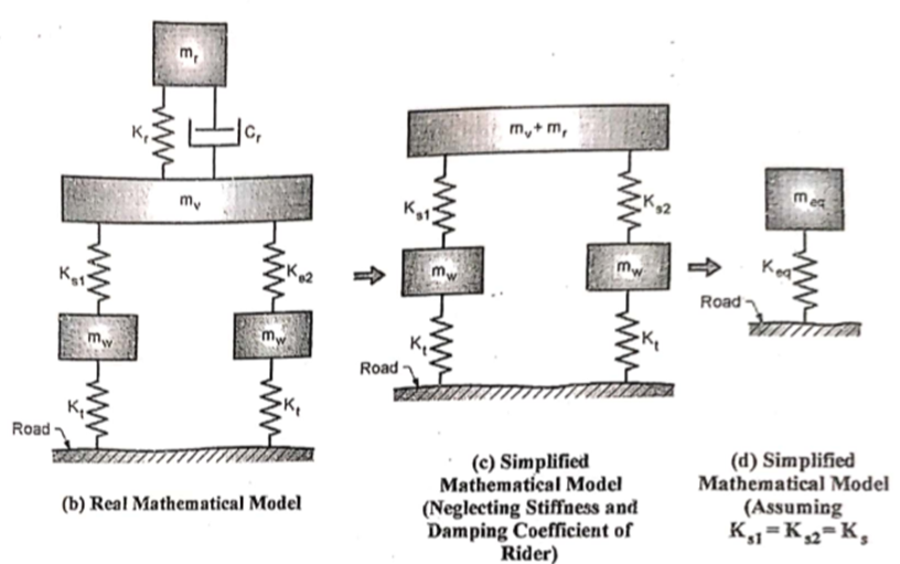
Fig (b) shows the real mathematical model with rider
If the stiffness and damping coefficient of rider is neglected, the mathematical model can be simplified as shown in Fig (c) and assuming the front and rear suspension are identical, the mathematical model can be simplified as shown in Fig (d)
2. Mathematical model of Motor Bike
Fig (a) below shows the physical model of a motor bike with rider.
(a) Physical model of motor bike
In order to develop a mathematical model of a physical system consisting of a motor bike and a rider, following parameters are considered:
mr = mass of rider
Kr = Stiffness of rider
Cr = Damping coefficient of rider
mv = mass of motor bike (except wheels)
Ks1 = Stiffness of rear suspension
Cs1 = Damping Coefficient of rear suspension
Ks2 = Stiffness of front suspension
Cs2 = Damping Coefficient of front suspension
Mw = mass of each wheel
Kt = Stiffness of each tyre
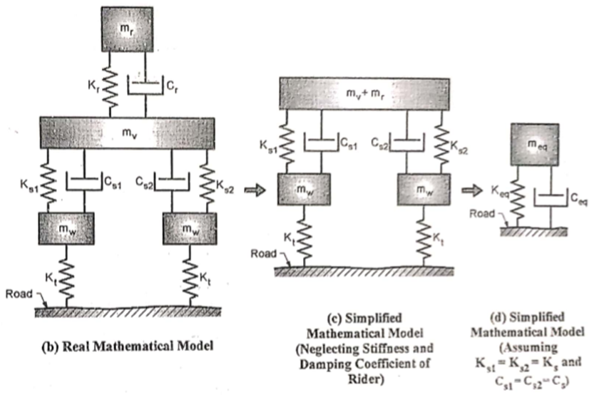
Fig (b) shows the real mathematical model of motor bike with rider.
If the stiffness and damping coefficient of rider is neglected, the mathematical model can be simplified as shown in Fig (c) and assuming the front and rear suspension are identical, the mathematical model can be simplified as shown in Fig (d)
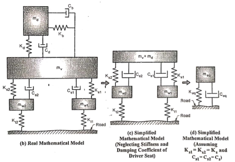
3. Mathematical model of Quarter Car
Fig (a) below shows the physical model of a car.
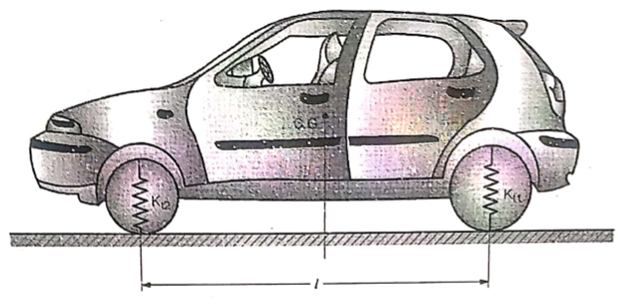
(a) Physical model of car
In order to develop a mathematical model of a physical system consisting of a car, following parameters are considered:
md = mass of driver and driver seat
Kd = Stiffness of driver seat spring
Cd = Damping coefficient of driver seat
Kb = Stiffness of back rest
Cb = Damping coefficient of back rest
mv = mass of car (except wheels)
Ks1 = Stiffness of rear suspension
Cs1 = Damping Coefficient of rear suspension
Ks2 = Stiffness of front suspension
Cs2 = Damping Coefficient of front suspension
mw1= mass of rear wheel and axle
mw2= mass of front wheel and axle
Kt1 = Stiffness of rear tyre
Kt2 = Stiffness of front tyre
Fig (b) shows the real mathematical model of car.
If the stiffness and damping coefficient of driver seat is neglected, the mathematical model can be simplified as shown in Fig (c) and assuming the front and rear suspension are identical, the mathematical model can be simplified as shown in Fig (d)
Free (Natural) Vibration
After disturbing the system, the external excitation is removed, then the system vibrates on its own. This type of vibration is known as free vibrations
eg: Simple pendulum.
3 types:-
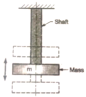
a) Longitudinal vibrations
When the particles of the shaft or disc move parallel to the axis of the shaft, then the vibrations are known as longitudinal vibrations. In this case the shaft is elongated and shortened alternately and thus the tensile and compressive stresses are induced alternately in the shaft.
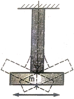
b) Transverse vibrations
When the particles of the shaft move approximately perpendicular to the axis of the shaft, then the vibrations are known as transverse vibrations. In this case the shaft is straight and bent alternately and bending stresses are induced in the shaft.
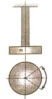
c) Torsional vibrations
When the particles of the shaft move in a circle about the axis of the shaft, then the vibrations are known as torsional vibrations.
In this case the shaft is twisted and untwisted alternately and torsional shear stresses are induced in the shaft to.
2. Forced Vibration
The vibration which is under the influences of external force is called forced vibration.
The external force applied to the body is periodic disturbing force created by unbalance.
The vibrations have the same frequency as the applied force. Due to the application of external forces the amplitude of these vibrations is maintained almost constant.
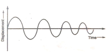
3. Damped vibration
When there is a reduction in amplitude over every cycle of vibration, the motion is said to be damped vibration.
That is if the vibrators system has a damper. The motion of the system will be opposed by it and the energy of the system will be dissipated in friction.
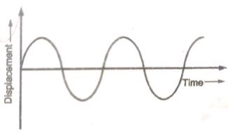
4. Undamped vibration
If there is no external resistance to the vibration of the system, then the vibration is undamped.
There is no damper. There is no loss of energy due to friction.
5. Deterministic vibration
If in the vibratory system the amount of external excitation is known in magnitude it is deterministic vibration.
6. Random vibration
If in the vibratory system the amount of external excitation is not known in magnitude it is random vibration
Non-deterministic vibrations
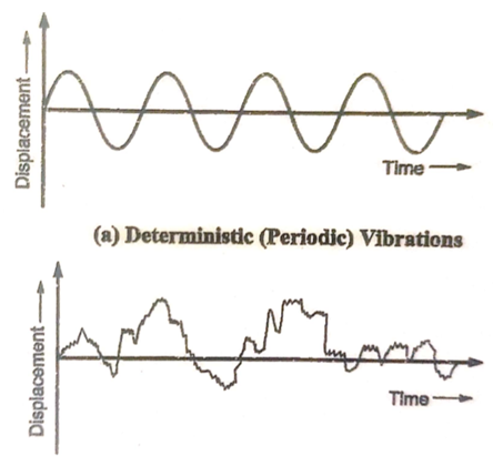
(b) random Vibration
Equivalent Stiffness and Damping Coefficient
Equivalent Spring (Stiffness)
In many practical applications, more than one spring may be used. To convert such system into equivalent mathematical model, it is necessary to replace springs into one equivalent spring with one equivalent stiffness.
Consider a system of two springs in series with stiffness K1 and K2
For springs in series
Deflection of equivalent spring
= Deflection of Spring 1 + Deflection of Spring 2

And
Force on equivalent spring
= Force on Spring 1 =Force on Spring 2

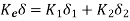
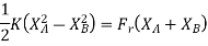
Two springs in series are to be replaced by an equivalent spring having stiffness Ke
We have,

Therefore
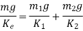
But, 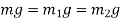
Therefore,

2. Spring in Parallel
Consider a system of two springs in parallel with stiffness K1 and K2
For springs in series
Deflection of equivalent spring
= Deflection of Spring 1 = Deflection of Spring 2

And
Force on equivalent spring
= Force on Spring 1 +Force on Spring 2
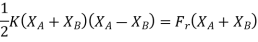
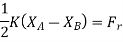
Two springs in parallel are to be replaced by an equivalent spring having stiffness Ke
We have,

and

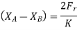
Therefore,
But, 
Therefore,

Equivalent Damper (Damper Coefficient)
In many applications, similar to springs, number of dampers are also used in combinations. To convert such system into equivalent mathematical model, it is necessary to replace dampers into one equivalent damper with one equivalent damping coefficient.
For dampers in series, equivalent damping coefficient is given by

2. Dampers in parallel
For dampers in parallel, equivalent damping coefficient is given by

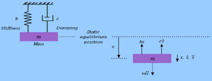
Formulation of Differential Equation of Motion for Undamped free Vibrations
A spring mass system as shown in Figure
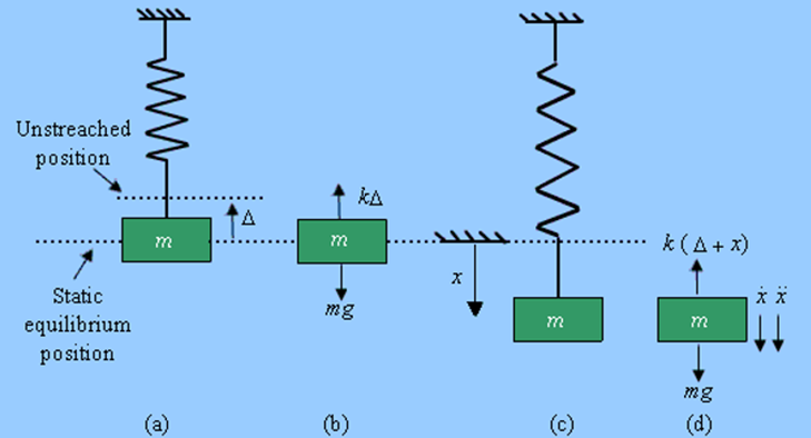
The direction of x in the downward direction is positive. Also, velocity, , acceleration,
  , and force, F, are positive in the downward direction
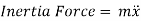
According to D’Alembert’s Principle, a body or a system which is not in static equilibrium due to acceleration it possesses, can be brought to static equilibrium by introducing the inertia force on it.
From Figure (d) on application of Newton's second law, we have

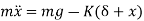
From fig (b) we have

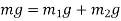
i.e. spring force due to static deflection is equal to weight of the suspended mass
So, the above equation becomes


2. D’Alembert’s Method
According to D’Alembert’s Principle, a body or a system which is not in static equilibrium due to acceleration it possesses, can be brought to static equilibrium by introducing the inertia force on it.
By D’Alembert’s Principle
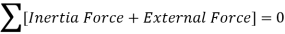

From fig (d)

Therefore,
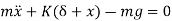
From fig (b) we have

We get,

3. Energy Method
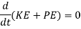
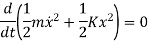
In a conservative system (i.e. with no damping) the total energy is constant, and differential equation of motion can also be established by the principle of conservation of energy.
By law of conservation of energy
Total Energy = Constant
KE + PE = Constant
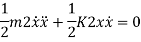
The equation will be given as
Kinetic Energy is given as

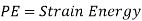
Potential energy PE is stored in the form of strain energy in elastic deformation
Therefore,


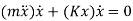

Natural Frequency of Free Undamped Vibratory systems
We have equation of motion

Or

We have fundamental equation of SHM as

where  is the natural frequency (in rads/sec)
By comparing Equation of motion and fundamental equation of SHM, we get

This Equation satisfies the simple harmonic motion condition.
The undamped free vibration executes the simple harmonic motion as shown in Figure
Since sine & cosine functions repeat after 2π radians (i.e. Frequency Time period = 2 π), we have

The time period (in second) can be written as

The natural frequency (in rad/sec or Hertz) can be written as

Also we have,


Therefore,

2. For Transverse Vibrations
Consider a cantilever beam of negligible mass carrying a concentrated mass ‘m’ at free end as shown in figure.
Due to gravitational force ‘mg’, the cantilever beam is deflected by  as shown in fig.

Forces acting on the mass beyond mean position are:
And
By D’Alembert’s Principle


Or

We have fundamental equation of SHM as

where  is the natural frequency (in rads/sec)
By comparing Equation of motion and fundamental equation of SHM, we get

The time period (in second) can be written as

The natural frequency (in rad/sec or Hertz) can be written as

Also we have,


Therefore,

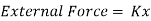
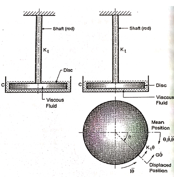
3. For Torsional Vibrations
Consider a disc having mass moment of inertia ‘I’ suspended on a shaft with negligible mass, as shown in fig.
Let,
 = angular displacement of disc from mean position in rad
 = mass of the disc in kg
 = Radius of gyration of disc in m
 = mass moment of inertia of disc =
  kg m2
kg m2
 = torsional stiffness of shaft in Nm/rad
Where,

 = Polar moment of Inertia of shaft =
 = Modulus of rigidity
 = length of shaft
 = diameter of shaft
Torques acting on the disc are

And

By D’Alembert’s Principle
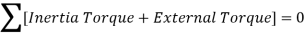

This is the equation of motion for torsional free undamped vibration.
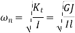
The fundamental equation of SHM is

By comparing both equations, we get,
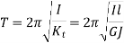
The time period (in second) can be written as
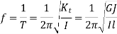
The natural frequency (in rad/sec or Hertz) can be written as
Damping
The external resistance which is provided to reduce the amplitude of vibrations is known as damping.
Damped Vibration
In vibratory system, if an external resistance is provided so as to reduce the amplitude of vibrations, the vibrations are known as damped vibrations
Damper
The damper is a unit which absorbs the energy of the vibratory system, thereby reducing the amplitude of vibration
Types of damping
Based on the method of providing the resistance to the vibrations, the damping is classified into three types
When the system vibrates in a fluid medium, the resistance is offered to the vibratory body and the damping is viscous damping. The resistance is known as damping resistance or damping force.
Damping force is proportional to the relative velocity between two surfaces


The constant of proportional ‘c’ is known as damping coefficient and is defined as damping force per unit velocity.
There are two types of viscous damping
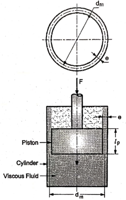
Fluid dashpot damping consists of a piston moving inside a cylinder filed with viscous fluid.
The damping coefficient ‘c’ for fluid dashpot damping can be given as

Where,
 = viscosity of fluid
 = clearance between piston and cylinder
 = length of piston
 = mean diameter of annular area between piston and cylinder
 = Cross-sectional area of piston
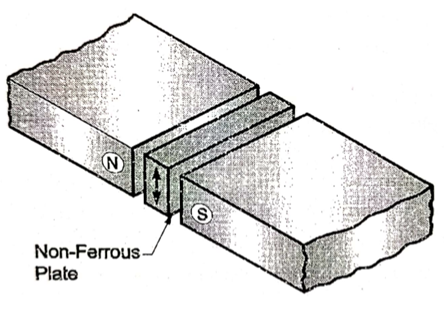
b. Eddy current damping
Eddy current damping is based on the principle of magnetic flux. It consists of a magnet and non-ferrous metal as shown in fig.
When the plate moves between north and south poles of a magnet in the direction perpendicular to the magnetic flux, current is induced in a plate and is proportional to the velocity of plate. This current is in the form of eddy current that sets up a magnetic field in the direction opposite to the original magnetic flux. Thus, there is resistance to the motion of the plate in a magnetic field which results in damping.
2. Coulomb or Dry Damping
Damping due to friction between two rubbing surfaces is called dry or coulomb damping.
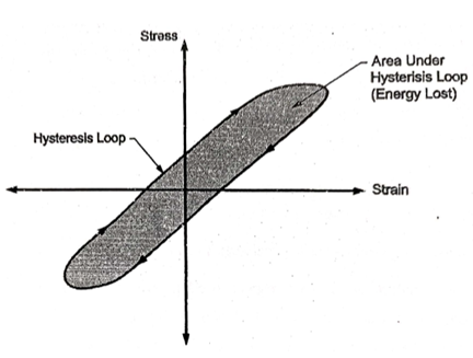
3. Material or structural or solid or Hysteresis Damping
This type of damping occurs in all vibrating system due to elasticity of material. When the materials are deformed, energy is absorbed and dissipated to surrounding in the form of heat. This effect due to internal friction of molecules of material is used for damping effect and damping is material or solid damping.
When a body with material damping is subjected to vibrations, the stress-strain diagram for a vibrating body is in the form of hysteresis loop as shown in fig. Hence it is also called as hysteresis damping.
Damped Free Vibration with Viscous Damping
Viscous damping force is expressed as,

Fig below shows the spring-mass-damper system with free body diagram
From free body diagram, we have

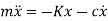
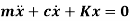
This is the differential equation of motion for damped free vibration.
Solution of differential equation
Above equation is a linear differential equation of second order and its solution can be written in the form,

where s is a constant (can be a complex number) and t is time
Differentiating above solution w.r.t  ,we get,

Again Differentiating, we get

Substituting all values in differential equation of motion
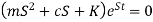
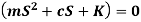
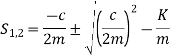
This equation is called is called characteristic equation of motion and can also be expressed as
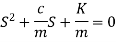
It is in the form of quadratic equation with two roots S1 and S2.

Therefore, two solutions of differential equation are


Hence the general solution of equation is given by the equation
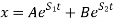
where A and B are integration constants to be determined from initial conditions.
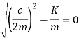
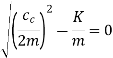
Critical damping coefficient
Critical damping coefficient ‘cc’ is that value of damping coefficient at which frequency of free damped vibration is zero and motion is aperiodic.
At c = cc, roots of the quadratic equation are equal
i.e. S1 = S2 = S
Implies, at c = cc


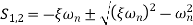
Damping factor or Damping Ratio ( )
)
Damping factor is defined as the ratio of damping coefficient to the critical damping coefficient.


And

Therefore, the roots of characteristic equation of motion becomes
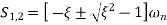
And
Therefore, the solution of differential equation is given as,

Initial conditions of Damped Free Vibration with Viscous Damping
A damped free vibration is a simple harmonic motion.
Initially, body or object is displaced with a distance equal to the amplitude of a SHM or vibration
i.e. at t = 0  =
=  0
0
Also, body is stationary at initial condition,
i.e. at t = 0  = 0
= 0
Cases of Damped Systems
Depending upon the value of damping factor or damping ratio, there are three cases of damped system
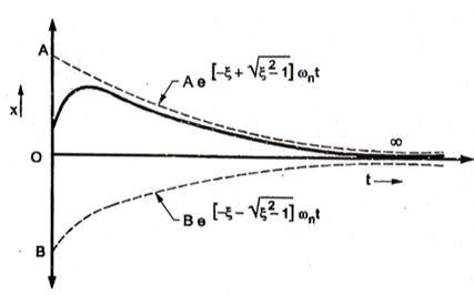
If the damping ratio ‘ ’ is greater than one or damping coefficient ‘c’ is greater than critical damping coefficient, then the system is said to be over damped.
 or
or 
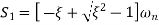
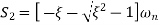
Two roots of over-damped equation are

And

The general solution of differential equation in over-damped system is given as,

The values of constant A and B are determined from initial conditions.
We get the values as,
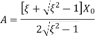
And
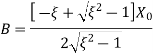
The general solution of differential equation in over-damped system becomes,

2. Critically damped system:
If the damping ratio ‘ ’ is equal to one or damping coefficient ‘c’ is equal to critical damping coefficient, then the system is said to be critically damped.
 or
or 
Two roots of over-damped equation are

And

Putting, 


The two roots are equal.
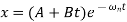
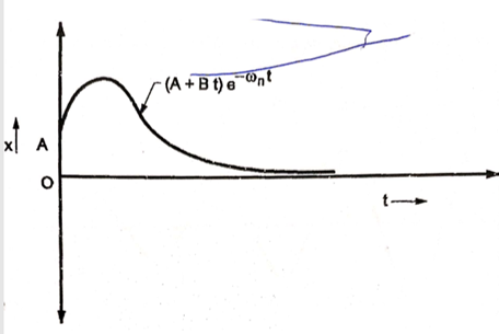
The general solution of differential equation in critically damped system is
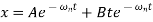
Using initial conditions, constants A and B are determined and given by
 0 and
0 and  0
0
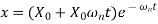
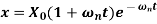
The general solution of differential equation in critically damped system becomes,
3. Under-damped system:
If the damping ratio ‘ ’ is less than one or damping coefficient ‘c’ is less than critical damping coefficient, then the system is said to be under damped.
 or
or 
Two roots of over-damped equation are

And

As, 
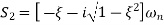
Both the roots are complex conjugate and are given by
And
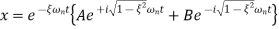
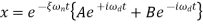
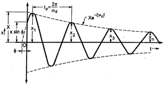
The general solution of differential equation in under-damped system is given as

Putting
 =
=
According to Euler’s theorem, the above equation can also be written as,
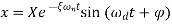
Where, X and  are determined from initial conditions.
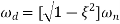
 is natural frequency for damped vibration and given by
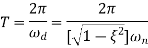
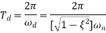
Time period for damped vibration is given as,
Logarithmic decrement
Rate of decay of free vibration is a measure of damping present in a system. Greater is the decay, larger will be the damping.
Damped (free) vibration, general equation of the response is given as
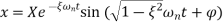
Defining a term logarithmic decrement which is defined as the natural logarithm of the ratio of any two successive amplitudes as shown Figure, where x1and x2 are two consecutive amplitudes in the free vibration displacement-time curve
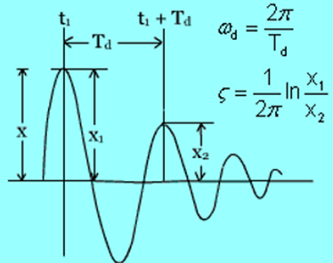
Since,

And,  is damped period
Where,  is damped natural frequency

We have, damped period as
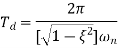
We get,

Above fig also shows that,
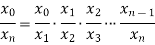
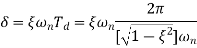
Taking log on both sides
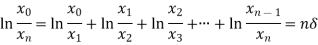
Therefore,

Where,
 is amplitude after ‘n’ cycles
 is amplitude at starting position
Damped free vibration with Coulomb or Dry Damping
In this type of damping, frictional force acts as a damping force.
Consider a spring mass system with mass ‘m’ sliding on a dry surface.
Forces acting on a displaced mass are:

Which is in opposite direction to displacement 
2. Friction force

Direction is opposite to that of velocity 
3. Inertia force
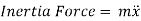
Direction is opposite to acceleration 
The Differential equation of motion is given as
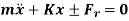
Sign of  depends upon the direction of displacement, velocity and acceleration.
Displacement is given as

In second and third quarter of motion, while

In first and fourth quarter of motion
Natural frequency is given by

Time period is given by

Rate of Decay of Vibration
Fig, below shows the rate of decay of vibration, i.e. loss of amplitude per cycle with coulomb damping
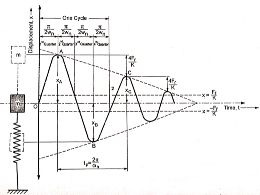
Consider a cycle starting from point A
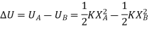
The total energy of system at point A is

The total energy of system at point B is

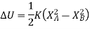
Loss of energy in half cycle from point A to B is
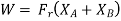
Work done against frictional force in half cycle from point A to point B is
Now,
Loss of energy = Work done against friction

This is loss of amplitude in half cycle from point A to point B
Similarly,
Loss of amplitude in half cycle from point B to point C is
Total loss of amplitude in one cycle is


The difference between any two successive amplitudes is constant and given by

References
1. Weaver, Vibration Problems in Engineering, 5th Edition Wiley India Pvt. Ltd, New Delhi.
2. Bell, L. H. and Bell, D. H., Industrial Noise Control – Fundamentals and Applications, Marcel Dekker Inc.
3. Alok Sinha, Vibration of Mechanical System, Cambridge university Press , India
4. Debabrata Nag, Mechanical Vibrations, Wiley India Pvt. Ltd, New Delhi.
5. Kelly S. G., Mechanical Vibrations, Schaums outlines, Tata McGraw Hill Publishing Co.Ltd., New Delhi.
6. Meirovitch, L., Elements of Mechanical Vibrations‖, McGraw Hill.
7. Ver, Noise and Vibration Control Engineering, Wiley India Pvt. Ltd, New Delhi.
8. Bies, D. and Hansen, C., Engineering Noise Control - Theory and Practice, Taylor and Francis.
9. Shrikant Bhave, Mechanical Vibrations Theory and Practice, Pearson, New Delhi


