Unit 3
Two Degree of Freedom Systems – Undamped Vibrations
Two degree of freedom system
The System which require two independent co-ordinates to specify its motion at configuration at instant is called two degree of freedom system. – Examples:
There are two equations of motion for a 2DOF system, one for each mass (more precisely, for each DOF). Such equations are called coupled differential equation.
They are generally in the form of couple differential equation that is, each equation involves all the coordinates.
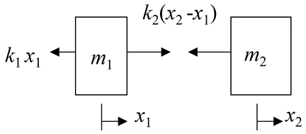
Undamped free longitudinal vibration on 2 DOF spring and mass system
Consider a system with 2 masses and 2 springs having 2 DOF as shown in fig.
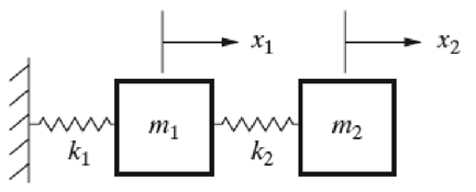
FBD of each mass is

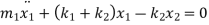
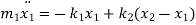
From FBD

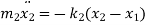
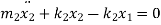
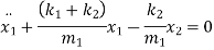
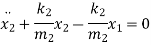
Rearranging the terms


These are the two equations of motion
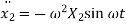
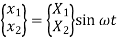
Solution for  and
and  are
are


 = Amplitude of vibration of mass
 = Amplitude of vibration of mass
A system with two degree of freedom vibrates in two principal mode of vibrations corresponding to its two natural frequencies.
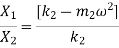
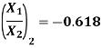
Mode shape is nothing but the ratio of amplitude, 
From two equations of motion, we get two mode shapes.

Differentiating two times, we get acceleration

Substituting values of displacement and acceleration in equation of motion for first mass


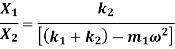
Substituting values of displacement and acceleration in equation of motion for first mass

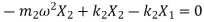


Equating both mode shapes
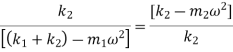


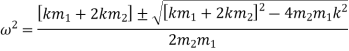
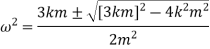
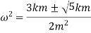
The above equation is a quadratic equation in  and gives two values of
i.e. two positive and two negative values of 
Two positive values of  gives two natural frequencies
  and
and  of the system.
Therefore, the above equation is called as frequency equation.
Mode shapes and natural frequency
A system with two degree of freedom vibrates in two principal mode of vibrations corresponding to its two natural frequencies.
Mode shape is nothing but the ratio of amplitude, 
From two equations of motion, we get two mode shapes.
We have, frequency equation as,

If 

Now, if 
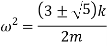
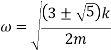
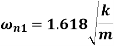
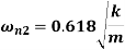
These are two natural frequencies of the system.
To find first mode shape, i.e. first ratio of amplitude
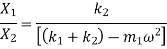
Substituting,  ;
;  and
and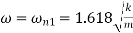
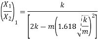
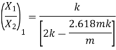

This is the first mode shape of system corresponding to first natural frequency 
Now,
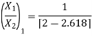
To find second mode shape, i.e. second ratio of amplitude
Substituting,  ;
;  and
and 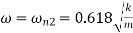
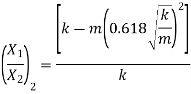
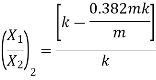
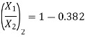
This is the second mode shape of system corresponding to second natural frequency 
Steps to find natural frequency and mode shapes of a 2 DOF spring coupled system
Step I: Draw FBD for each mass
Step II: Write equation of motion for each mass from FBD. There are 2 equations in 2 DOF system.
Step III: The solution for two equations is in the form

Find acceleration by differentiating the solution two times.
Step IV: Substitute displacement and acceleration in both equation of motions
Step V: Find amplitude ratio  from each equation and equate them.
Step VI: After equating, we get a quadratic equation in  which gives two values of
i.e. two positive and two negative values of 
Two positive values of  gives two natural frequencies
  and
and  of the system.
Step VII: Solve the quadratic equation and find two natural frequencies  and
and  of the system
Step VIII: Substitute both the natural frequencies simultaneously in the equation of any one amplitude ratio  . This gives mode shapes. One gets two mode shapes corresponding to two natural frequencies.
Consider a same example of two degree of freedom system.

FBD of each mass is
From FBD

Rearranging the terms

Again, rearranging the terms
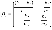
Above equation can be written in matrix form as

Solution for  and
and  is
is
Therefore, acceleration is given by
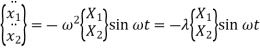
Where,
 = Eigen value
And,
 Eigen Vector
Substituting displacement and acceleration in equation of motion
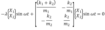
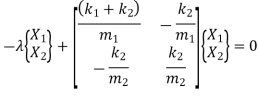
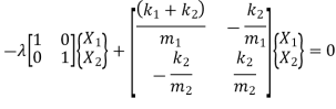
Where,

 Eigen Vector
 = Eigen value
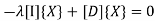
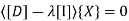
The non-zero solution for eigen vector  will occur when,
  is a singular matrix
i.e. 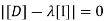
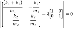
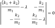
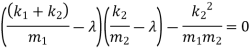
From the above equation, eigen value  can be obtained
One gets two values of 
Now, 
From two values of one get two natural frequencies.
Now, to find mode shapes,
Substitute two eigen values simultaneously in the following equation

Now, Find amplitude ratio i.e. mode shapes for each eigen value.
Free Torsional Vibration for 2 DOF system
Consider a torsional system as shown in Fig.
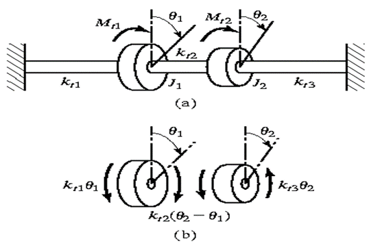
(a) Torsional system (b) FBD of disc
The differential equations of motion are derived from fig (b) as
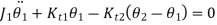

The solution for this torsional system is similar to that of longitudinal system.
Free Torsional Vibration of two rotor system
A two-rotor system consists of a shaft with two rotors A and B at its end as shown in fig.
Node Point
There is a point or a section of the shaft which remains untwisted. This point or section where amplitude of vibration is zero is known as node point or nodal section.
Two rotor system with shafts AB carrying rotors A and B at ends can be considered as equivalent to two single rotor system with:
Let,
 and
and  = Mass moment of Inertia of rotors A and B
 and
and  = Torsional stiffness of shaft NA and NB
 and
and  = Amplitude of vibration of rotor A and rotor B
 = Polar Moment of Inertia of shaft
Circular natural frequency for single rotor system is given by
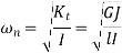
Therefore, circular natural frequency for shaft NA and rotor A

And, circular natural frequency for shaft NB and rotor B

To find position of node i.e. 
The circular frequencies of shaft are same


Total length of shaft is

Now, once  and
and  are known, both the natural frequencies can be determined
Ratio of Amplitude:
From fig (b)


Or

Zero frequency vibration of two rotor system
If two rotors A and B rotate in same direction with same speed, then the shaft is said to vibrate with zero frequency. In this condition, amplitude of vibration at both ends will be in same direction. Such behavior is called as zero frequency behavior.
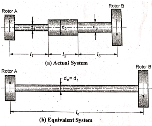
Torsionally Equivalent system
In two rotor and three rotor system, it is assumed that the diameter of shaft is uniform. But in actual practice, the shaft may have different diameters for different lengths. If the shafts of different diameters are replaced by a theoretically equivalent shaft of a uniform diameter, as shown in fig, such shafts are called as Torsionally equivalent shaft.
Let  ,
,  and
and  be the angles of twist for shafts of length
  ,
,  and
and  with diameters
  ,
,  and
and  respectively.
Let  , be the angle of twist fortorsionally equivalent shaft of length
  with diameter
  .
.
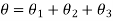
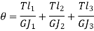
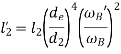
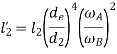
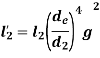
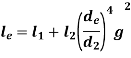
Total Angle of twist for actual shaft

Angle of twist for equivalent shaft

Angle of twist of equivalent shaft =Total Angle of twist for actual shaft
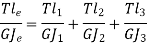
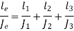
Now,

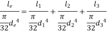
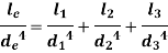
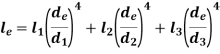
Generally, diameter of equivalent shaft is taken as one of the diameters of actual shaft. For, e.g. 
In many applications, the body is subjected to combined rectilinear and angular motions. For example, when brakes are applied on a moving car, two motions of car occur simultaneously.
Consider a system as shown in fig
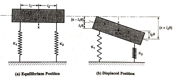
Let ‘I’ be the MI of a body with mass ‘m’ about CG
 be the angular displacement at any instant and
 be the linear displacement at that instant.
From fig (b) compression of spring can be given as


FBD of the system is shown below
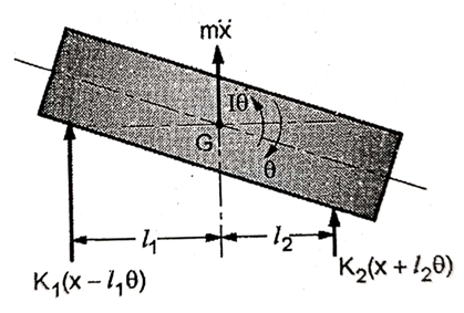
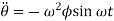
From fig., the differential equation of motion for the system are

And

Or


The above equations have both terms  and
and  . Such equations are called as coupled equations.
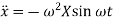
Solution for these two equations under steady state conditions are given by


Where  and
and  are amplitudes of vibration for linear and angular motion respectively
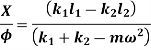
Therefore,
Substituting values of  ,
,  ,
,  and
and  in below equation


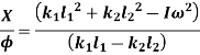
Now, substituting values of  ,
,  ,
,  and
and  in below equation


Equating both equations
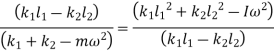

Solving above equation, we get

The above frequency equation is the quadratic equation in 
Solving the above equation for  one get two positive and two negative values for
  .
.
These two positive values of  are two natural frequencies for the system.
Many a times, torsional vibration is observed in a geared system. The geared system is shown in figure (a).
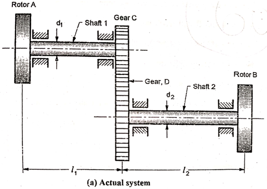
The shaft 1 carries a rotor A at one end and pinion to another end. The shaft 2 carries a gear meshing with pinion at one end and rotor B at another end.
The gear system may be replaced by an equivalent two rotor system, if the inertia is neglected. This system consists of continuous shaft with rotor A at one end and rotor B’ at another end. (fig. b)
If inertia is not neglected, then the equivalent system will be a three rotor system as shown in fig (c).
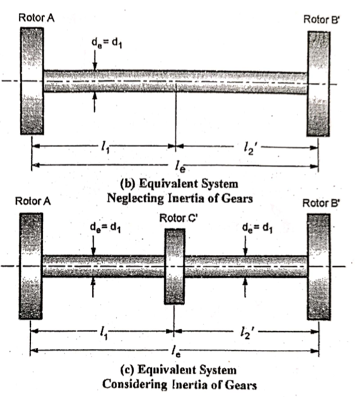
If Inertia of gear is neglected.
The geared system will b equivalent to two rotor system if:
Consider,
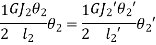
KE of Geared system = KE of Equivalent System
KE of section  + KE of section
  = KE of section
  +KE of section
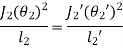
KE of section  = KE of section


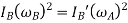


Where,
 gear ratio
Now consider,
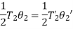
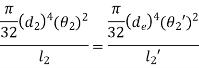
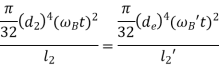
Strain Energy of Geared system = Strain Energy of Equivalent system
Strain Energy of section  + Strain Energy of section
= Strain Energy of section  +Strain Energy of section
Strain Energy of section  = Strain Energy of section
But,

Let,
 polar moment of Inertia of shaft 2 =
 polar moment of Inertia of shaft 2 =
Total length of equivalent shaft is

If moment of Inertia is considered,
An additional rotor C’ must be placed at distance  from the rotor A on the shaft.
Such that,

Where,
 and
and  are the MI of pinion C and gear D
The system will act as three rotor system with rotor A, rotor B’ and rotor C’
References
1. Weaver, Vibration Problems in Engineering, 5th Edition Wiley India Pvt. Ltd, New Delhi.
2. Bell, L. H. and Bell, D. H., Industrial Noise Control – Fundamentals and Applications, Marcel Dekker Inc.
3. Alok Sinha, Vibration of Mechanical System, Cambridge university Press , India
4. Debabrata Nag, Mechanical Vibrations, Wiley India Pvt. Ltd, New Delhi.
5. Kelly S. G., Mechanical Vibrations, Schaums outlines, Tata McGraw Hill Publishing Co.Ltd., New Delhi.
6. Meirovitch, L., Elements of Mechanical Vibrations‖, McGraw Hill.
7. Ver, Noise and Vibration Control Engineering, Wiley India Pvt. Ltd, New Delhi.
8. Bies, D. and Hansen, C., Engineering Noise Control - Theory and Practice, Taylor and Francis.
9. Shrikant Bhave, Mechanical Vibrations Theory and Practice, Pearson, New Delhi


