Unit 4
Balancing
Need of Balancing
Static Balancing
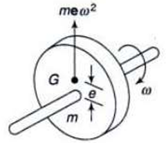
A system is said to be in static balance if the net dynamic force acting on the system is zero.
Σ F = 0
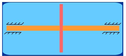
The net dynamic force acting on a shaft is zero. This requires that the line of action of three centrifugal forces must be same. In other words, the center of line of masses of the system must lie on the axis of the rotation
Dynamic Balancing
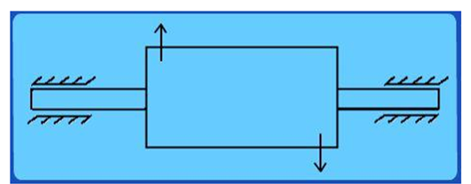
A system is said to be in dynamic balance if the net dynamic forces as well as net dynamic couples are equal to zero respectively.
Σ F = 0
Σ T = 0
The net dynamic force acting on a shaft is zero. This requires that the line of action of three centrifugal forces must be same. In other words, the center of line of masses of the system must lie on the axis of the rotation.
The net couple due to dynamic forces acting on a shaft is equal to zero. In other words, the algebraic sum of moments about any point on the plane must be zero. i.e. the axis of shaft must coincide with the axis of rotation.
Consider a disturbing mass m1 attached to a shaft rotating at ω rad/s as shown in Fig.
Let r1 be the radius of rotation of the mass m1 (i.e. distance between the axis of rotation of the shaft and the center of gravity of the mass m1).
We know that the centrifugal force exerted by the mass m1 on the shaft,

This centrifugal force acts radially outwards and thus produces bending moment on the shaft.
In order to counteract the effect of this force, a balancing mass (m2) may be attached in the same plane of rotation as that of disturbing mass (m1) such that the centrifugal forces due to the two masses are equal and opposite.
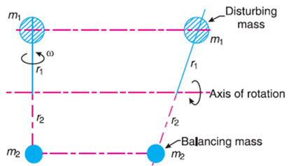
Let r2 be the radius of rotation of the mass m2 (i.e. distance between the axis of rotation of the shaft and the center of gravity of the mass m2).
Therefore, centrifugal force exerted by the mass m2 on the shaft,
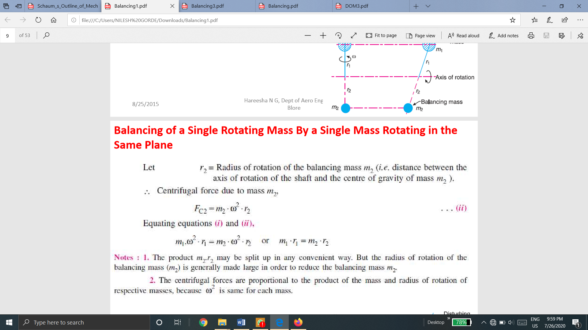
Equating both equations

In the previous arrangement for balancing gives rise to a couple which tends to rock the shaft in its bearings.
Therefore, in order to put the system in complete balance, two balancing masses are placed in two different planes, parallel to the plane of rotation of the disturbing mass, in such a way that they satisfy the following two conditions of equilibrium.
i.e. The system must be dynamic balance
Consider, any number of masses (say 4) of magnitude m1, m2, m3 and m4 at distances of r1, r2, r3, r4 from the axis of rotating shaft.
Let  ,
,  ,
,  and
and  be angles of these masses with horizontal line OX as shown in fig.
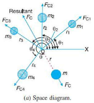
Let these masses rotate about an axis through O and perpendicular to page of paper, with a constant angular velocity  rad/sec.
The magnitude and position of the balancing mass may be found out analytically or graphically as discussed below:
The magnitude and direction of the balancing mass may be obtained, analytically, as discussed below:
We know that,
Summation of horizontal component of centrifugal forces,

Summation of vertical component of centrifugal forces,


Where,
 = Balancing mass
 = Radius of rotation
2. Graphical Method
The magnitude and position of the balancing mass may also be obtained graphically as discussed below:
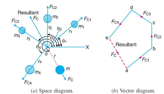
 Resultant Centrifugal force

 Resultant of
  ,
,  ,
,  and
and 
When several masses revolve in different planes, they may be transferred to a reference plane (briefly written as R.P.), which may be defined as the plane passing through a point on the axis of rotation and perpendicular to it. The effect of transferring a revolving mass (in one plane) to a reference plane is to cause a force of magnitude equal to the centrifugal force of the revolving mass to act in the reference plane, together with a couple of magnitude equal to the product of the force and the distance between the plane of rotation and the reference plane.
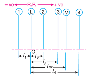
(a) Planer position of masses
In order to have a complete balance of the several revolving masses in different planes, the following two conditions must be satisfied :
1. The forces in the reference plane must balance, i.e. the resultant force must be zero.
2. The couples about the reference plane must balance, i.e. the resultant couple must be zero.
Let us now consider four masses m1, m2, m3 and m4 revolving in planes 1, 2, 3 and 4 respectively as shown in Fig. (a).
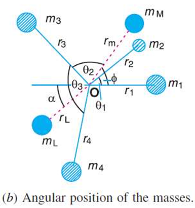
The relative angular positions of these masses are shown in the end view Fig. (b)
The magnitude of the balancing masses mL and mM in planes L and M may be obtained as discussed below:
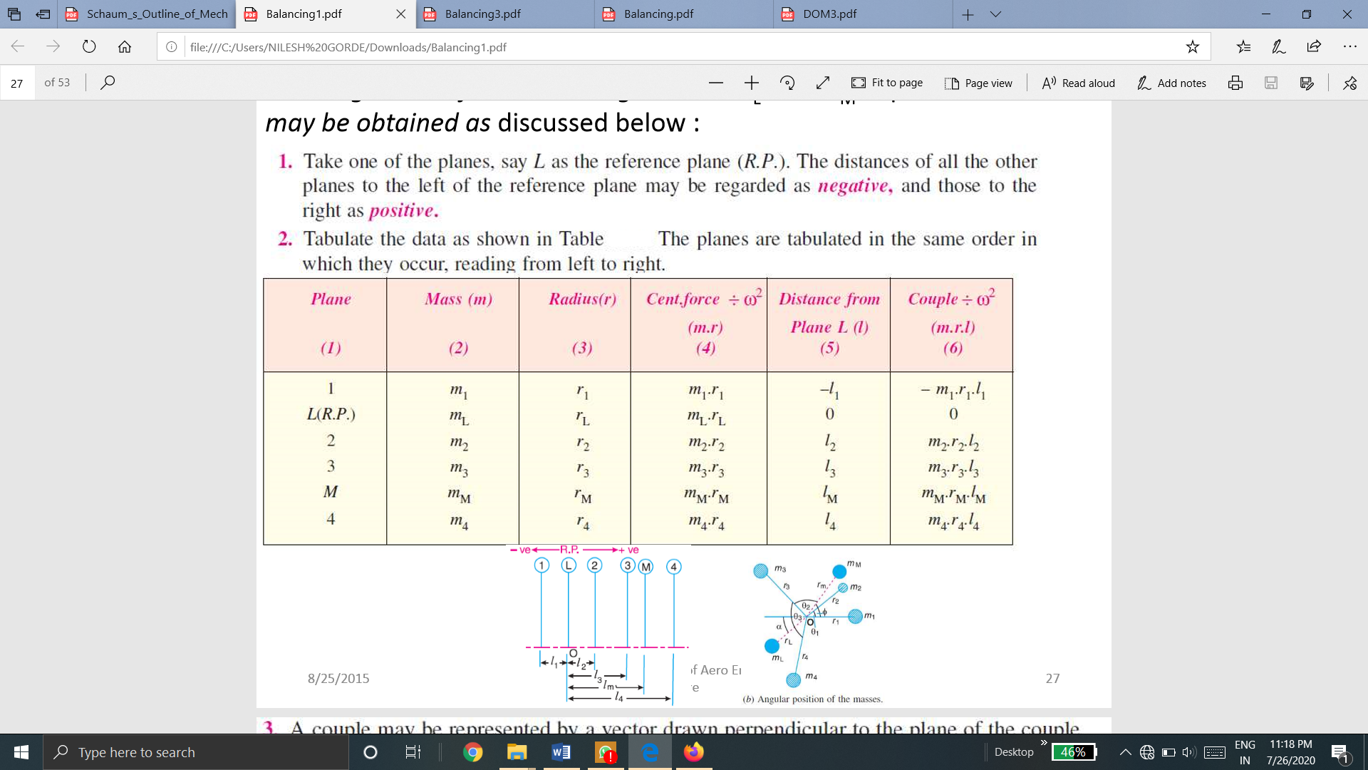


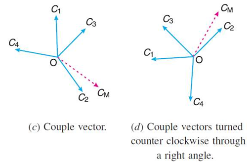


From this expression, the value of the balancing mass mM in the plane M may be obtained, and angle of inclination  of this may be measured from fig (b)
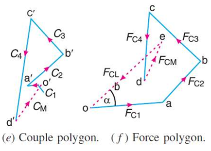

From this expression, the value of the balancing mass mL in the plane L may be obtained.
Consider a horizontal reciprocating engine mechanism as shown in Fig.
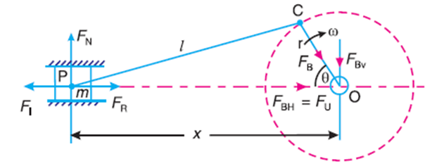
FR = Force required to accelerate the reciprocating parts.
FI = Inertia force due to reciprocating parts,
FN = Force on the sides of the cylinder walls or normal force acting on the cross-head guides, and
FB = Force acting on the crankshaft bearing or main bearing.
Since FR and FI, are equal in magnitude but opposite in direction, therefore they balance each other.
The horizontal component of FB (i.e. FBH) acting along the line of reciprocation is also equal and opposite to FI.
This force FBH = FU is an unbalanced force or shaking force and required to be properly balanced.
The force on the sides of the cylinder walls (FN) and the vertical component of FB (i.e. FBV) are equal and opposite and thus form a shaking couple of magnitude FN x X or FBV x X.
From above, we see that the effect of the reciprocating parts is to produce a shaking force and a shaking couple. Since the shaking force and a shaking couple vary in magnitude and direction during the engine cycle, therefore they cause very objectionable vibrations.
Thus, the purpose of balancing the reciprocating masses is to eliminate the shaking force and a shaking couple. In most of the mechanisms, we can reduce the shaking force and a shaking couple by adding appropriate balancing mass, but it is usually not practical to eliminate them completely. In other words, the reciprocating masses are only partially balanced.
Consider a reciprocating engine mechanism as shown in Fig.
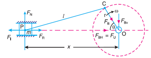
Let,
m = Mass of the reciprocating parts,
L = Length of the connecting rod PC,
r = Radius of the crank 0C,
θ = Angle of inclination of the crank with the line of stroke PO,
ω = Angular speed of the crank,
n = Ratio of length of the connecting rod to the crank radius = L/r.
the acceleration of the reciprocating parts is approximately given by the expression

Therefore, inertia force due to reciprocating parts,

The horizontal component of the force exerted on the crank shaft bearing (i.e. FBH) is equal and opposite to inertia force (FI). This force is an unbalanced one and is denoted by FU.
Therefore, unbalanced force is,


Characteristics of primary and secondary unbalanced forces


The primary unbalanced force ( ) may be considered as the component of the centrifugal force produced by a rotating mass m placed at the crank radius r, as shown in Fig.
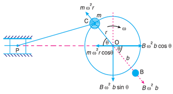
The primary force acts from O to P along the line of stroke. Hence, balancing of primary force is considered as equivalent to the balancing of mass m rotating at the crank radius r.
This is balanced by having a mass B at a radius b, placed diametrically opposite to the crank pin C

A little consideration will show, that the primary force is completely balanced if B.b = m.r, but the centrifugal force produced due to the revolving mass B has also a vertical component (perpendicular to the line of stroke) of magnitude ( )
)
This force remains unbalanced. The maximum value of this force is equal to Bω2b when θ is 90° and 270°, which is same as the maximum value of the primary force mω2r
From the above discussion, we see that in the first case, the primary unbalanced force acts along the line of stroke whereas in the second case, the unbalanced force acts along the perpendicular to the line of stroke.
The maximum value of the force remains same in both the cases. • It is thus obvious, that the effect of the above method of balancing is to change the direction of the maximum unbalanced force from the line of stroke to the perpendicular of line of stroke.
As a compromise, let a fraction ‘c’ of the reciprocating masses is balanced, such that: cmr = B.b
Therefore, Unbalanced force along the line of stroke

and unbalanced force along the perpendicular to the line of stroke

Balancing of Primary Forces
The multi-cylinder engines with the cylinder center lines in the same plane and on the same side of the center line of the crankshaft, are known as In-line engines.
The following two conditions must be satisfied in order to give the primary balance of the reciprocating parts of a multi-cylinder engine:
1) The algebraic sum of the primary forces must be equal to zero. In other words, the primary force polygon must close; and
2) The algebraic sum of the couples about any point in the plane of the primary forces must be equal to zero. In other words, the primary couple polygon must close.
The primary unbalanced force due to the reciprocating masses is equal to the component parallel to the line of stroke, of the centrifugal force produced by the equal mass placed at the crankpin and revolving with it.
Therefore, in order to give the primary balance of the reciprocating parts of a multi-cylinder engine, it is convenient to imagine the reciprocating masses to be transferred to their respective crankpins and to treat the problem as one of revolving masses.
Notes :
Balancing of Secondary Forces
When the connecting rod is not too long (i.e. when the obliquity of the connecting rod is considered), then the secondary disturbing force due to the reciprocating mass arises.
The secondary force,
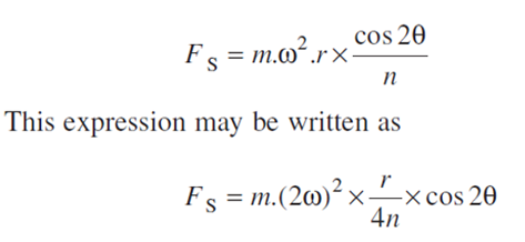
As in case of primary forces, the secondary forces may be considered to be equivalent to the component, parallel to the line of stroke, of the centrifugal force produced by an equal mass placed at the imaginary crank of length r/4n and revolving at twice the speed of the actual crank (i.e. 2 ω) as shown in Fig.
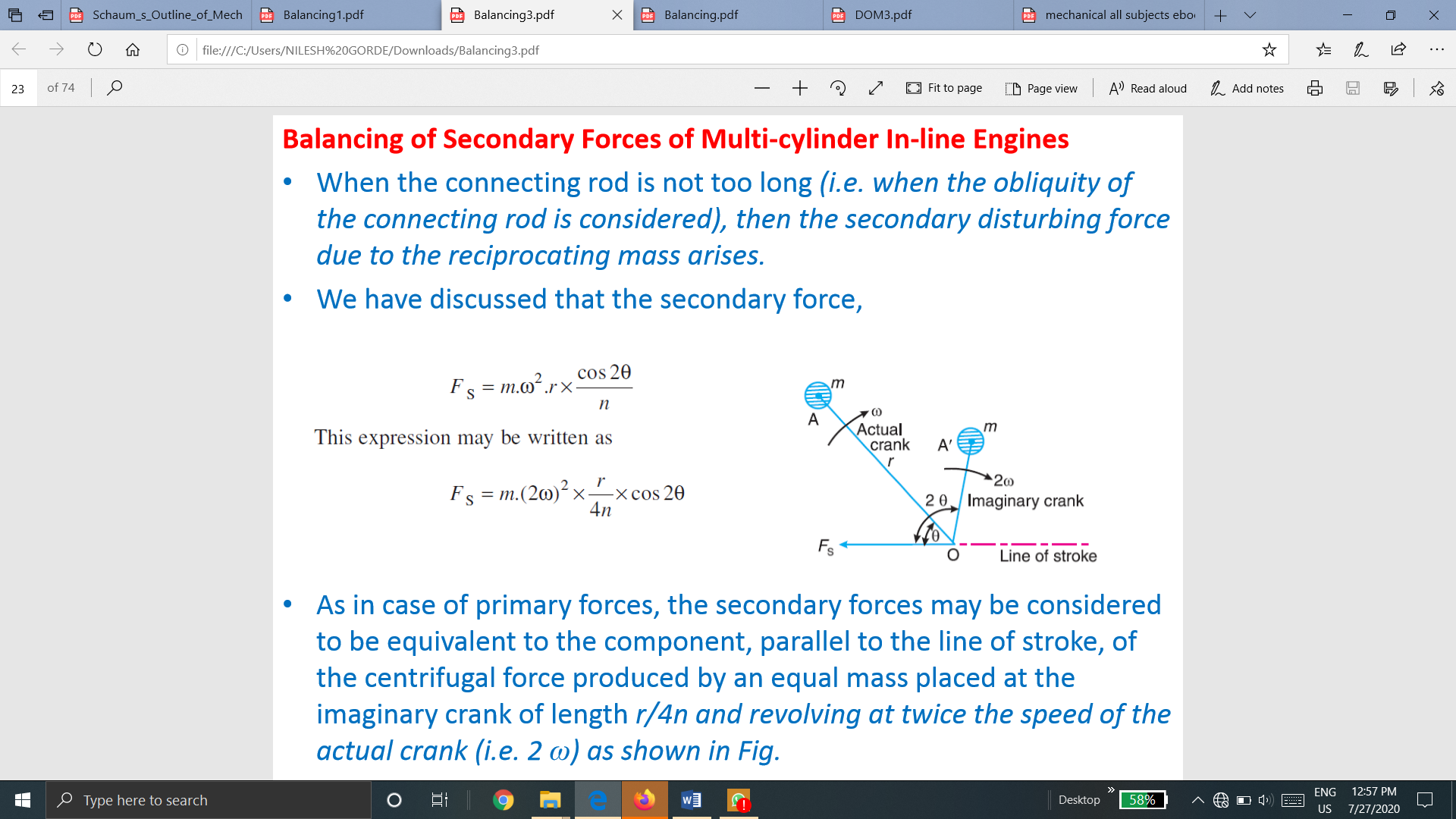
Thus, in multi-cylinder in-line engines, each imaginary secondary crank with a mass attached to the crankpin is inclined to the line of stroke at twice the angle of the actual crank. • The values of the secondary forces and couples may be obtained by considering the revolving mass. This is done in the similar way as discussed for primary forces.
The following two conditions must be satisfied in order to give a complete secondary balance of an engine:
1. The algebraic sum of the secondary forces must be equal to zero. In other words, the secondary force polygon must close, and
2. The algebraic sum of the couples about any point in the plane of the secondary forces must be equal to zero. In other words, the secondary couple polygon must close.
Note: The closing side of the secondary force polygon gives the maximum unbalanced secondary force and the closing side of the secondary couple polygon gives the maximum unbalanced secondary couple.
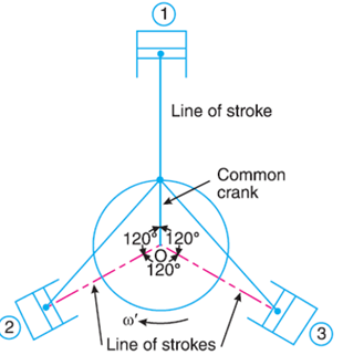
The method of direct and reverse cranks is used in balancing of radial or V-engines, in which the connecting rods are Connected to a common crank. Since the plane of rotation of the various cranks (in radial or V-engines) is same, therefore there is no unbalanced primary or secondary couple. Consider a reciprocating engine mechanism as shown in Fig.
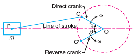
Let the crank OC (known as the direct crank) rotates uniformly at ω radians per second in a clockwise direction. Let at any instant the crank makes an angle θ with the line of stroke OP.
The indirect or reverse crank OC' is the image of the direct crank OC, when seen through the mirror placed at the line of stroke. A little consideration will show that when the direct crank revolves in a clockwise direction, the reverse crank will revolve in the anticlockwise direction.
We shall now discuss the primary and secondary forces due to the mass (m) of the reciprocating parts at P.
Considering the primary forces
We have already discussed that primary force is

This force is equal to the component of the centrifugal force along the line of stroke, produced by a mass (m) placed at the crank pin C.
Now let us suppose that the mass (m) of the reciprocating parts is divided into two parts, each equal to m/2.
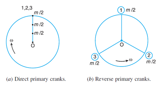
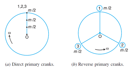
It is assumed that m/2 is fixed at the direct crank (termed as primary direct crank) pin C and m/2 at the reverse crank (termed as primary reverse crank) pin C', as shown in Fig.
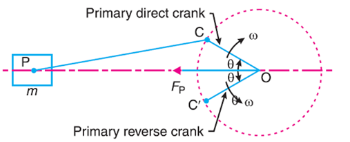
We know that the centrifugal force acting on the primary direct and reverse crank
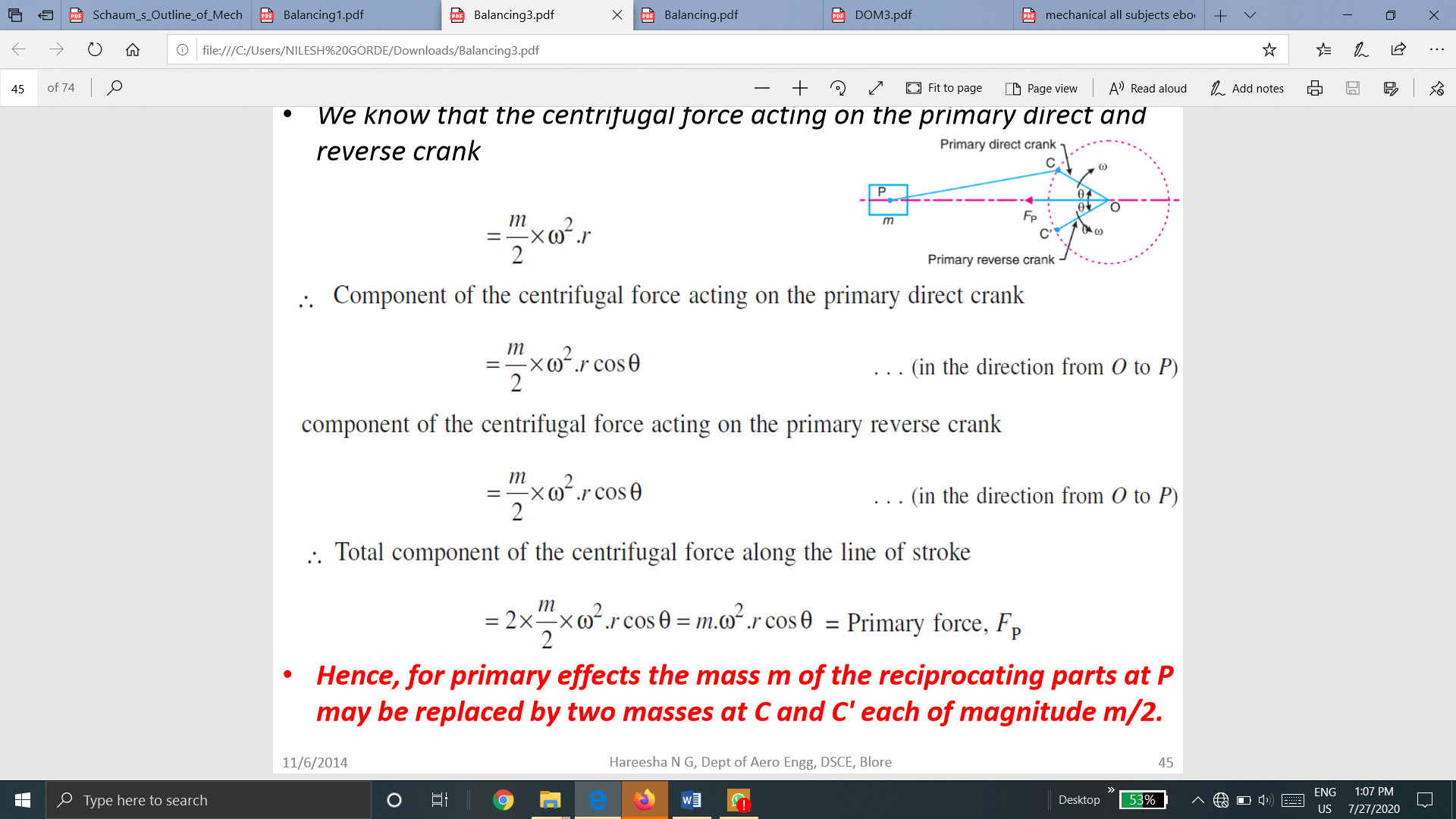
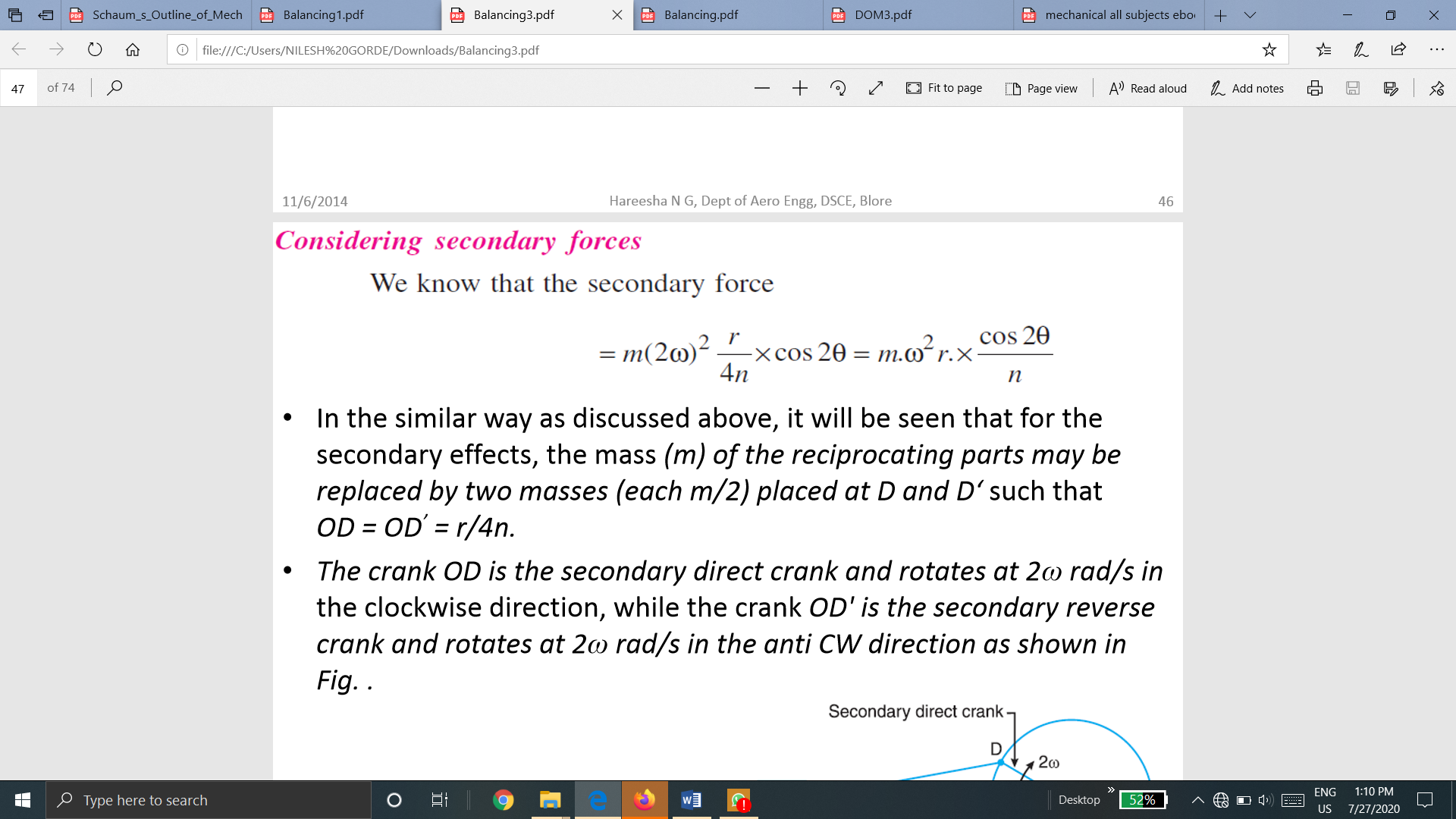
Hence, for primary effects the mass m of the reciprocating parts at P may be replaced by two masses at C and C' each of magnitude m/2.
Note :
• The component of the centrifugal forces of the direct and reverse cranks, in a direction perpendicular to the line of stroke, are each equal to  , but opposite in direction. Hence these components are balanced.
Considering the Secondary forces
We know that the secondary force
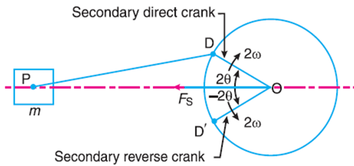
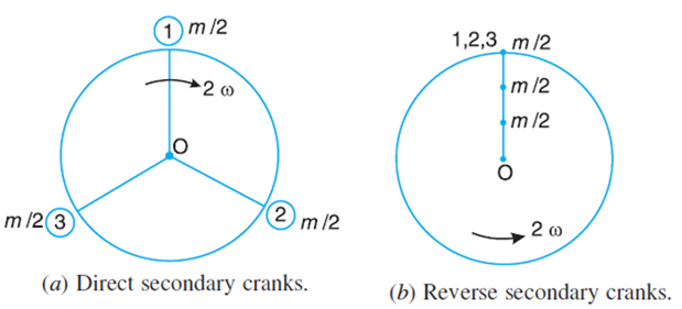
In the similar way as discussed above, it will be seen that for the secondary effects, the mass (m) of the reciprocating parts may be replaced by two masses (each m/2) placed at D and D’ such that OD = OD’ = r/4n.
The crank OD is the secondary direct crank and rotates at 2ω rad/s in the clockwise direction, while the crank OD' is the secondary reverse crank and rotates at 2ω rad/s in the anti CW direction as shown in Fig.
Maximum primary force acting on the frame of the compressor
The primary direct and reverse crank positions as shown in Fig (a) and (b), are obtained as discussed below:
Maximum secondary force acting on the frame of the compressor
The secondary direct and reverse crank positions as shown in Fig. (a) and (b) are obtained as discussed below:
From Fig.(a), we see that the secondary direct cranks form a balanced system.
Therefore, there is no unbalanced secondary force due to the direct cranks. From Fig. (b) we see that the resultant secondary force is equivalent to the centrifugal force of a mass 3 m/2 attached at a crank radius of r/4n and rotating at a speed of 2ω rad/s in the opposite direction to the crank.2
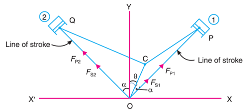
Consider a symmetrical two cylinder V-engine as shown in Fig
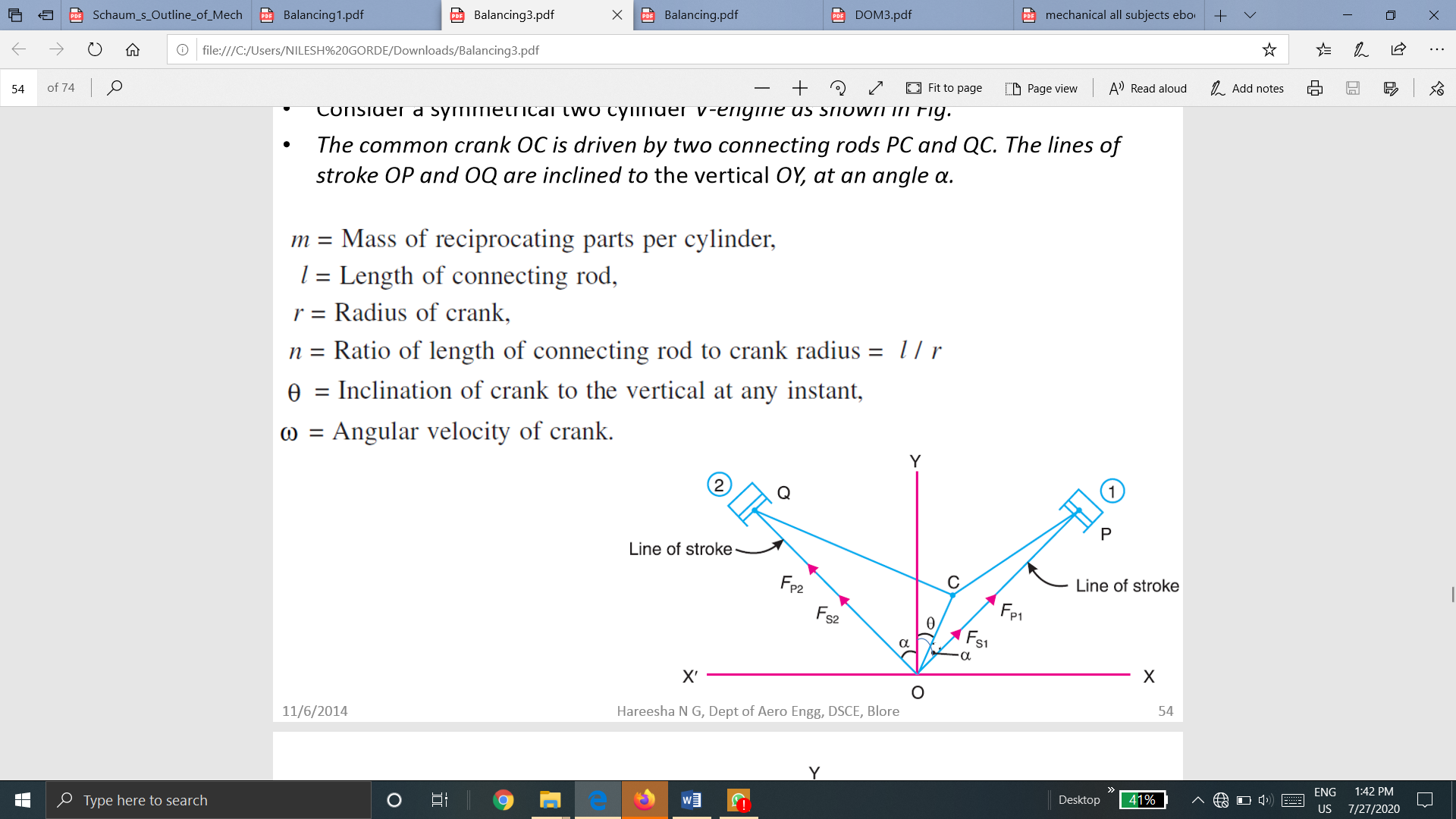
The common crank OC is driven by two connecting rods PC and QC. The lines of stroke OP and OQ are inclined to the vertical OY, at an angle α.


The balancing of V-engines is only considered for primary and secondary forces as discussed below:
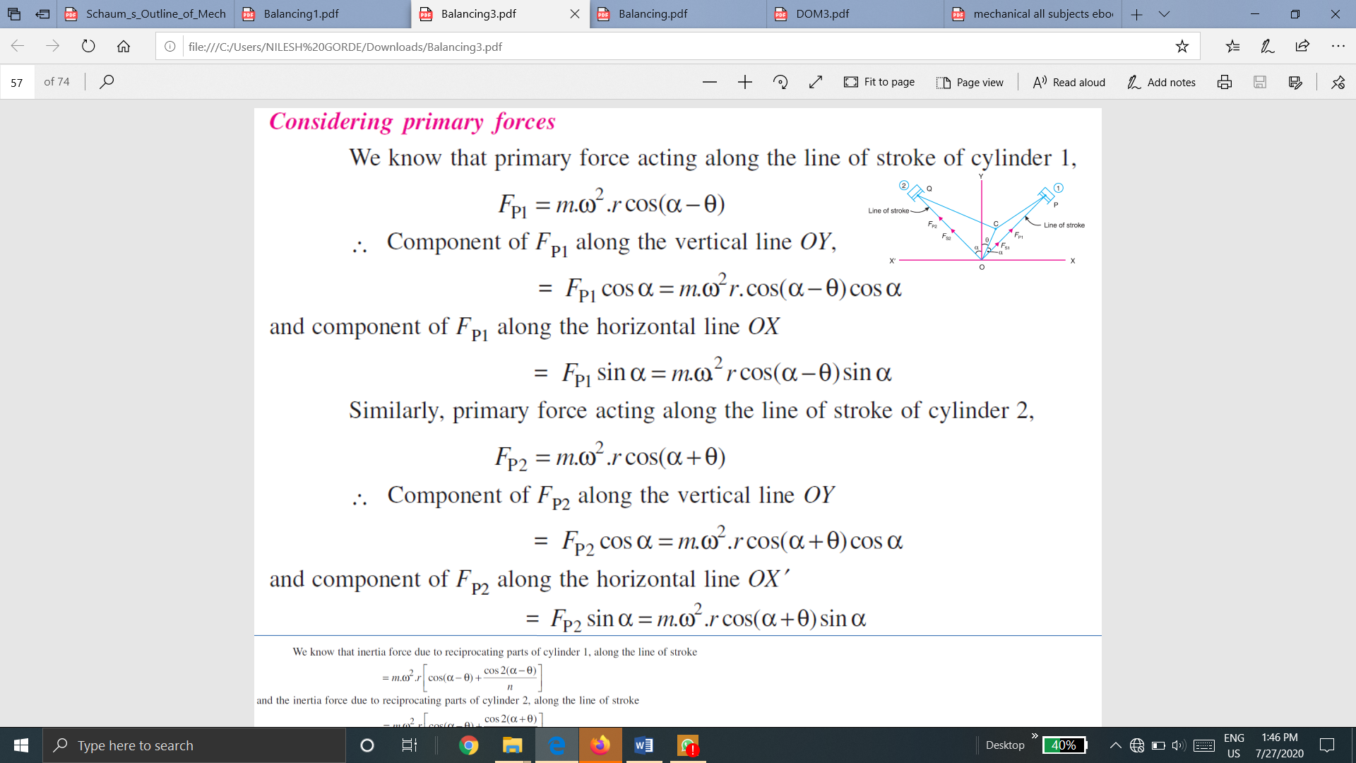
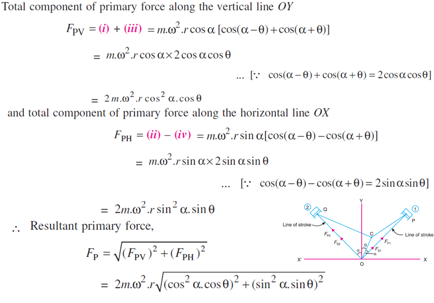
Considering Primary Force
We know that primary force acting along the line of stroke of cylinder 1
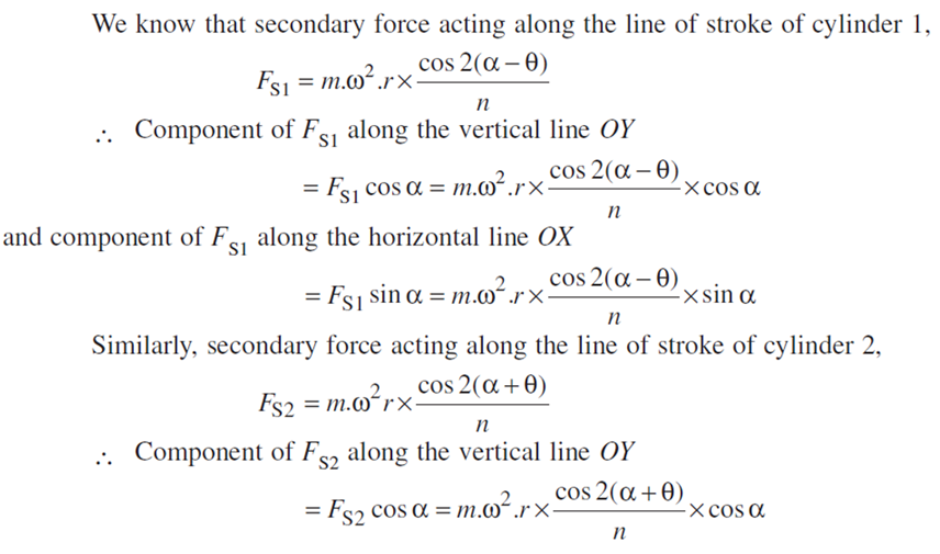
Considering secondary forces
