Unit 1
Basics of Fluid Power and Pumps
1.1.1 Fluid Power:
“Fluid power is the technology that deals with the generation, control, and transmission of forces and movement with the use of pressurized fluids in a confined system.”
Advantages of a fluid power system:
Disadvantages of a fluid power system:
The fluid power system is categorized as hydrostatic and hydrodynamic systems.
1.1.2 Hydrostatic System:
“The system in which fluid pressure is used to transmit power is called hydrostatic system.”
1.1.3 Hydrodynamic System:
“The system in which fluid motion is used to transmit power is called a hydrodynamic system.”
1.2.1 Hydraulics:
“Hydraulics is the technology concerned with the conveyance of liquids through pipes and channels, especially as a source of mechanical force or control.”
Advantages of Hydraulic system
Disadvantages of Hydraulic system
1.2.2 Pneumatics:
“Pneumatics is a branch of engineering that makes use of gas or pressurized air.”
Advantages of Pneumatic system
Disadvantages of Pneumatic systems
Difference between Hydraulics and Pneumatics
Oil hydraulics employs pressurized liquid petroleum oils and synthetic oils, and pneumatics employs compressed air which is exhausted to the atmosphere after performing the work.
1.3.1 Density
“Density (ρ) is defined as mass per unit volume.”

1.3.2 Specific Weight
“Specific weight (γ) is defined as weight per unit volume.”

Density and specific weight are related by

1.3.3 Specific Gravity
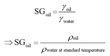
“Specific gravity (SG) of a given fluid is defined as the specific weight of the fluid divided by the specific weight of water.”

1.3.4 Pressure
“Pressure is defined as force per unit area. It is the amount of force acting over a unit area.”
The pressure developed at the bottom of a column of any liquid is called hydrostatic pressure and is given by
P = ρgh
1.3.5 Bulk Modulus
Bulk modulus is a measure of the compressibility of a liquid and is required when it is desired to calculate oil volume changes for high pressure and large system volumes such as forging pressures or natural frequencies generally caused by the interaction of fluid compressibility and moving mass.

1.3.6 Viscosity
“The viscosity of a fluid is a measure of its resistance to shear or angular deformation.”
Dynamic Viscosity:
“It is defined as the force requires to move a flat surface of the unit area at unit velocity when it is separated by a unit thickness.”

Where,
µ is known as the coefficient of viscosity, the dynamic viscosity, or simply the viscosity of the fluid.
τ is shearing stress between two thin sheets of fluid
du/dy is the velocity gradient.
The dimension of dynamic Viscosity is Ns/m2 or poise.
Kinematic Viscosity:
“Kinematic Viscosity is the ratio of dynamic viscosity to the density of the same fluid.”

Kinematic Viscosity is measured in m2/s or stoke.
1.3.7 Reynolds Number:
It is a dimensionless number referred to as compressible or incompressible fluid flow. It was postulated by a British engineer Osborne Reynolds. The Reynolds number set criteria by which the fluid flow regime may be distinguished:

Where, ρ is the density (kg/m3), v is the velocity of the fluid (m/s), D is the diameter of the pipe (m) and µ is the absolute or dynamic viscosity (Pa s or ms/m2).
“A hydraulic fluid is the transmitting medium of a hydraulic system.”
It is, therefore, an essential part of the system and we must know enough about it to ensure that the hydraulic system works efficiently. The most common liquid that is used as a medium in fluid power systems is petroleum-based mineral oil.
1.4.1 Functions of Hydraulic Fluids:
In fluid power systems, a hydraulic fluid has to perform various functions such as the following:
1.4.2 Properties of Hydraulic Fluids:
The various properties required for an ideal hydraulic fluid are as follows:
It is almost impossible to achieve all these properties in hydraulic fluid. Although we can select a good fluid with desirable properties, some of the characteristics of a fluid change with usage.
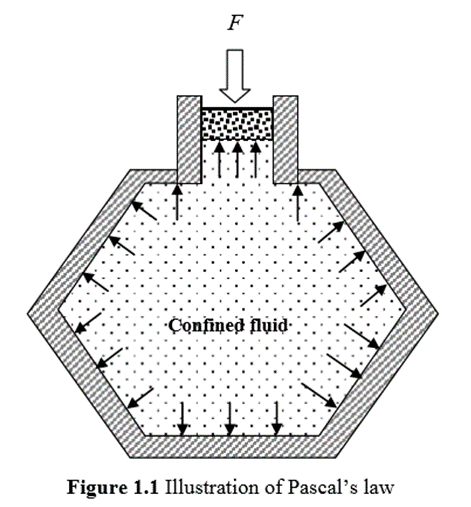
Pascal’s Law:
Pascal’s law states that “the pressure exerted on a confined fluid is transmitted undiminished in all directions and acts with equal force on equal areas and at right angles to the containing surfaces.”

In Fig. 1.1, a force is being applied to a piston, which in turn exerts pressure on the confined fluid. The pressure is equal everywhere and acts at right angles to the containing surfaces.
Multiplication of Force:
The most useful feature of fluid power is the ease with which it can multiply force. This is accomplished by using an output piston that is larger than the input piston.
This system consists of an input cylinder on the left and an output cylinder on the right that is filled with oil. When the input force is Fin on the input piston, the pressure in the system is given by
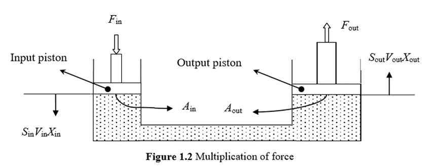
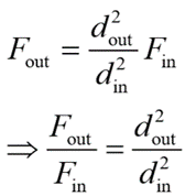
Here to obtain the output force, the input force is multiplied by a factor that is equal to the ratio of the output piston area to the input piston area. If the output piston area is x times the input piston area, then the output force is x times the input force. Generally, the cross-sectional area of the piston is circular.
The area is given by
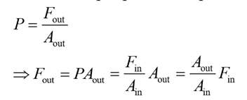
Hence, the above equation can be written as

A fluid distribution system is composed of pipes, tubings, hose assemblies, manifolds and fittings so arranged that the fluid is carried with minimum losses from the reservoir through controls and working components and is then returned.
All materials used to convey fluid power are commonly classified as conductors and the various fittings for connecting components are classified as connectors.
More than one type of conductor may be used in the same installations. Conductors are generally steel regardless of conductor material and they may be coated with cadmium or some other corrosion-resistant material.
The choice of pipe, tube, or hose depends on the operating pressures of the system and flow. Other important factors include environmental conditions, type of fluid and operating temperature, shock loads, relative motion between connected parts, practicality, and compliance with certain standards.
The following points must be considered both while designing the system and selecting a conductor:
Liquids such as water or petrol flow much easier than other liquids such as oil. The resistance to flow is essentially a measure of the viscosity of a fluid. The greater the viscosity of a fluid, the less readily it flows and the more is the energy required to move it. This energy is lost because it is dissipated as heat.
Energy losses also occur in valves and fittings.
Let us understand various losses that occur the inflow of fluid through fluid transfer elements as well as fluid control elements.
These losses are categorized as:
1.7.1 Major Energy loses:
“The losses of energy in the system due to friction are termed as major energy losses.”
These losses can be calculated by using,
Darcy-Weisback Equation
If fluid flows through a length of pipe and pressure is measured at two stations along the pipe, one finds that the pressure decreases in the direction of flow. This pressure decrease is mainly due to the friction of the fluid against the pipe wall. Friction is the main cause of energy losses in fluid power systems.
Head losses in a long pipe in which the velocity distribution has become fully established or uniform along its length can be found by Darcy’s equation as,
Where f is the Darcy friction factor, L is the length of pipe (m), D is the inside diameter of the pipe (m), v is the average velocity (m/s) and g is the acceleration of gravity (m/s2).
for laminar flow, the friction factor equals the constant 64 divided by the Reynolds number:

1.7.2 Minor losses:
Minor losses in fluid flow take place because of various reasons which are discussed below:

2. Loss of head due to a sudden contraction

3. Loss of head at the entrance of the pipe

4. Loss of head because of bend in the pipe

5. Loss of head at the exit of the pipe
6. Loss of head in various valves and pipe fittings
“The function of a pump is to convert mechanical energy into hydraulic energy.”
It is the heart of any hydraulic system because it generates the force necessary to move the load. Mechanical energy is delivered to the pump using a prime mover such as an electric motor. A partial vacuum is created at the inlet due to the mechanical rotation of the pump shaft. Vacuum permits atmospheric pressure to force the fluid through the inlet line and into the pump. The pump then pushes the fluid mechanically into the fluid power actuated devices such as a motor or a cylinder.
Pumps are classified into three different ways and must be considered in any discussion of fluid power equipment.
1.10.1 Classification based on displacement:
“Non-positive displacement pumps are primarily velocity-type units that have a great deal of clearance between rotating and stationary parts. “
Non-displacement pumps are characterized by a high slip that increases as the backpressure increases, so that the outlet may be completely closed without damage to the pump or system. Non-positive pumps do not develop a high pressure but move a large volume of fluid at low pressures.
They have essentially no suction lift. Because of large clearance space, these pumps are not self-priming. In other words, the pumping action has too much clearance space to seal against atmospheric pressure. The displacement between the inlet and the outlet is not positive.
The two most common types of hydrodynamic pumps are the centrifugal and the axial flow propeller pumps.
The advantages are as follows:
The disadvantages are as follows:
b. Positive Displacement Pump (hydrostatic pump):
“Positive displacement pumps, in contrast, have very little slips, are self-priming and pump against very high pressures.”
But their volumetric capacity is low. Positive displacement pumps have a very close clearance between rotating and stationary parts and hence are self-priming.
Positive displacement pumps eject a fixed amount of fluid into the hydraulic system per revolution of the pump shaft. Such pumps are capable of overcoming the pressure resulting from mechanical loads on the system as well as the resistance of flow due to friction. This equipment must always be protected by relief valves to prevent damage to the pump or system.
A majority of fluid power pumps fall in this category, including gear, vane and piston pumps.
Positive displacement pumps are classified based on the following characteristics:
2. Displacement characteristics: Based on displacement characteristics, positive displacement pumps are classified as follows:
3. Type of pumping element.
The advantages of positive displacement pumps over non-positive displacement pumps are as follows:
1.10.2 Classification Based on Delivery:
“Constant volume pumps always deliver the same quantity of fluid in a given time at the operating speed and temperature.”
b. Variable Delivery Pumps
“The output of variable volume pumps may be varied either manually or automatically with no change in the input speed to the pump.”
1.10.3 Classification Based on Motion:
“The fluid is delivered and imparted through the rotary motion of the pump.”
b. Reciprocating motion type pump
“The fluid is delivered and imparted through the reciprocating motion of the pump.”
1.10.4 Differences between positive displacement pumps and non-positive displacement pumps
Positive Displacement Pumps | Non-positive Displacement Pumps |
The flow rate does not change with head | The flow rate decreases with head |
The flow rate is not much affected by the viscosity of the fluid | The flow rate decreases with the viscosity |
Efficiency is almost constant with head | Efficiency increases with the head at first and then decreases |
There are three types of vane pumps:
- Unbalanced Vane Pump with Fixed Delivery
Construction
Fig. Unbalanced Vane pump with fixed delivery
Working
1.11.2 Balanced Vane Pump with Fixed Delivery:
Construction
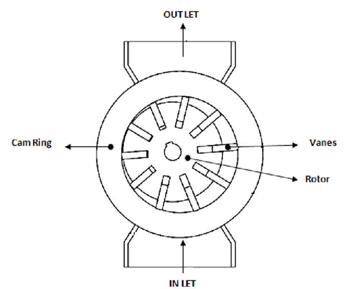
Fig. Balanced Vane Pump with fixed delivery
Working
1.11.3 Variable displacement vane pump:
The schematic diagram of the variable displacement vane pump is shown in Fig. Variable displacement features can be brought into vane pumps by varying eccentricity between the rotor and the cam ring. Here in this pump, the stator ring is held against a spring-loaded piston. The system pressure acts directly through a hydraulic piston on the right side. This forces the cam ring against a spring-loaded piston on the left side. If the discharge pressure is large enough, it overcomes the compensated spring force and shifts the cam ring to the left.
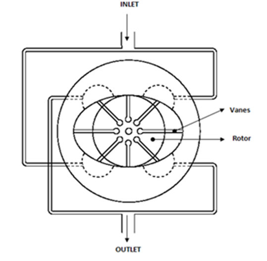
Fig. Operation of Variable displacement Vane Pump
1.11.4 Advantages and disadvantages of Vane Pump
The advantages of vane pumps are as follows:
The disadvantages of vane pumps are as follows:
1.11.5 The expression for the Theoretical Discharge of Vane Pumps
Let DC be the diameter of a cam ring in m, DR the diameter of the rotor in m, L the width of the rotor in m, e the eccentricity in m, VD the pump volume displacement in m3/rev and emax the maximum possible eccentricity in m.
From geometry, the maximum possible eccentricity,
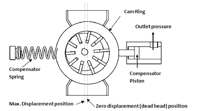
The maximum value of eccentricity produces the maximum volumetric displacement

Above equation can be simplified as,

The actual volumetric displacement occurs when emax = e. Hence,
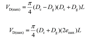
When the pump rotates at N rev/min (RPM), the quality of discharge by the vane pump is given by


Gear pumps are less expensive but limited to pressures below 140 bar. It is noisy in operation than either vane or piston pumps. Gear pumps are invariable of fixed displacement type, which means that the amount of fluid displaced for each revolution of the drive shaft is theoretically constant.
1.12.1 External Gear Pumps
Construction
External gear pumps are the most popular hydraulic pumps in low-pressure ranges due to their long operating life, high efficiency, and low cost. They are generally used in a simple machine.
The most common form of the external gear pump is shown in Fig.
It consists of a pump housing in which a pair of precisely machined meshing gears runs with minimal radial and axial clearance.
One of the gears, called a driver, is driven by a prime mover. The driver drives another gear called a follower.

Fig. Operation of External Gear pump
Working
As the teeth of the two gears separate, the fluid from the pump inlet gets trapped between the rotating gear cavities and pump housing.
The trapped fluid is then carried around the periphery of the pump casing and delivered to the outlet port.
The teeth of precisely meshed gears provide almost a perfect seal between the pump inlet and the pump outlet.
When the outlet flow is resisted, pressure in the pump outlet chamber builds up rapidly and forces the gear diagonally outward against the pump inlet.
When the system pressure increases, imbalance occurs. This imbalance increases mechanical friction and the bearing load of the two gears.
Hence, the gear pumps are operated to the maximum pressure rating stated by the manufacturer.
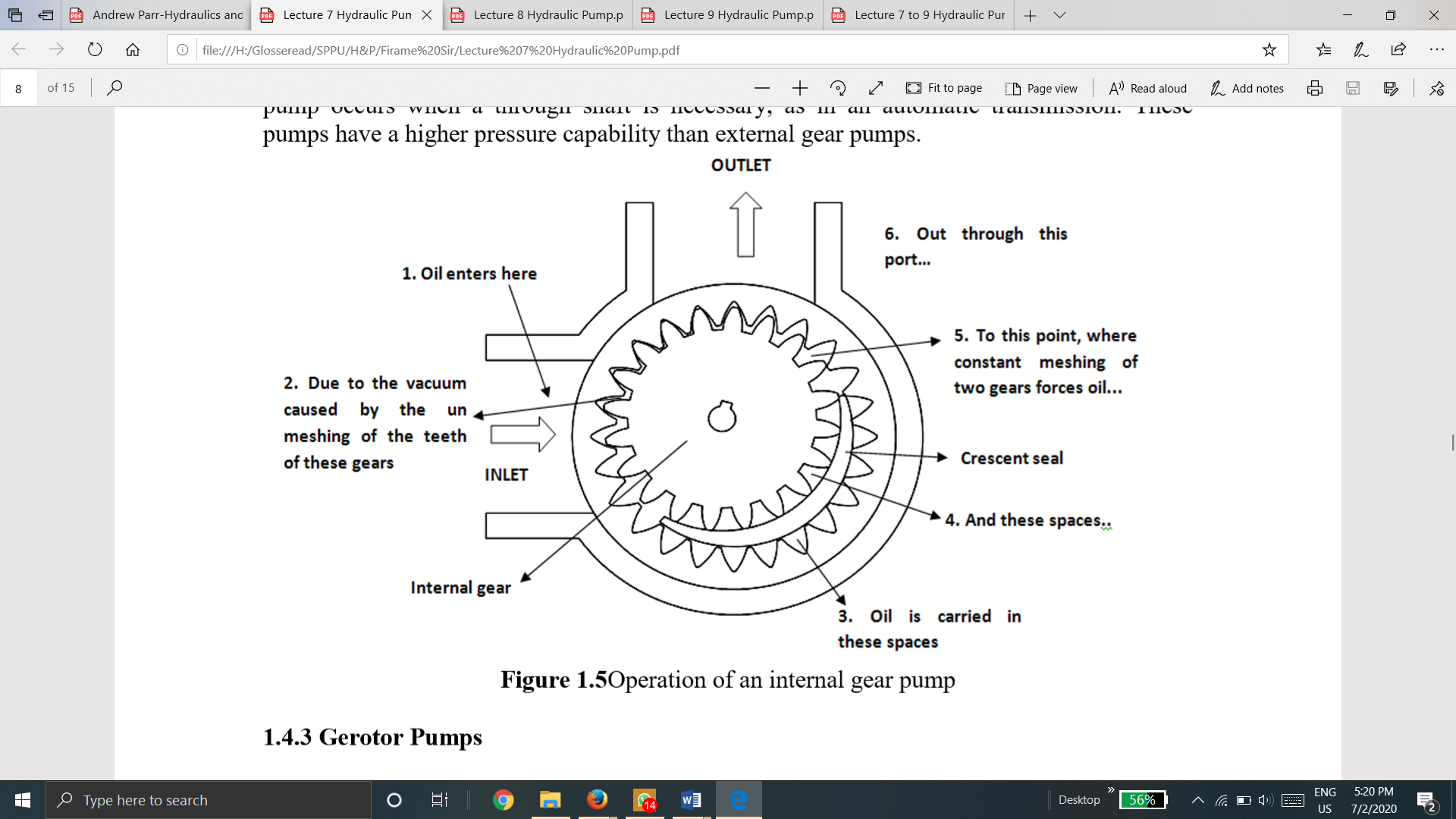
1.12.2 Internal Gear Pump:
Construction
Internal gear pump consists of two gears: An external gear and an internal gear. The crescent placed in between these acts as a seal between the suction and discharge.

Fig. Operation of Internal Gear Pump
Working
When a pump operates, the external gear drives the internal gear and both gears rotate in the same direction.
The fluid fills the cavities formed by the rotating teeth and the stationary crescent. Both the gears transport the fluid through the pump.
The crescent seals the low-pressure pump inlet from the high-pressure pump outlet.
The fluid volume is directly proportional to the degree of separation and these units may be reversed without difficulty.
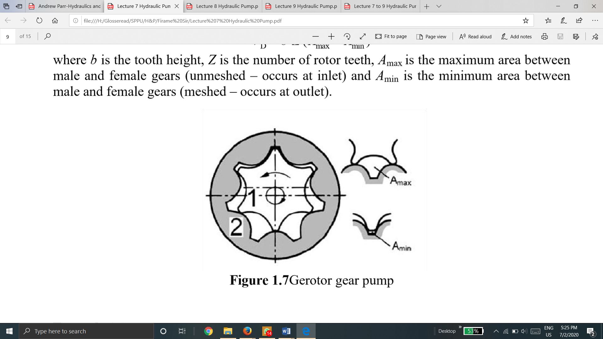
1.12.3 Gerotor Pumps
Gerotor pumps operate in the same manner as internal gear pumps. The inner gear rotor is called a gerotor element. The gerotor element is driven by a prime mover and during the operation drives the outer gear rotor around as they mesh together.
The gerotor has one tooth less than the outer internal idler gear. Each tooth of the gerotor is always in sliding contact with the surface of the outer element.
The teeth of the two elements engage at just one place to seal the pumping chambers from each other. On the right-hand side of the pump, shown in Fig, pockets of increasing size are formed, while on the opposite side, pockets decrease in size.
The pockets of increasing size are suction pockets and those of decreasing size are discharge pockets. Therefore, the intake side of the pump is on the right and discharge side on the left.
Pumping chambers are formed by the adjacent pair of teeth, which are constantly in contact with the outer element, except for clearance. Refer to Fig, as the rotor is turned, its gear tips are accurately machined so that they precisely follow the inner surface of the outer element. The expanding chambers are created as the gear teeth withdraw.
The chamber reaches its maximum size when the female tooth of the outer rotor reaches the top dead center. During the second half of the revolution, the spaces collapse, displacing the fluid to the outlet port formed at the side plate.
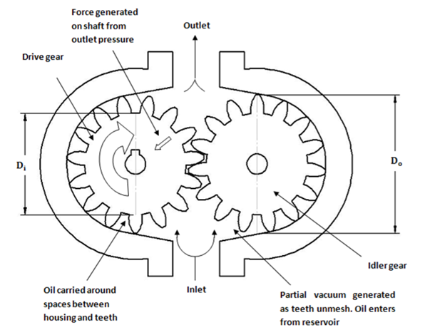
Fig. Gerotor Pump
1.12.4 Advantages and disadvantages of gear pumps
The advantages are as follows:
The disadvantages are as follows:
1.12.5 Expression for the theoretical flow rate of an external gear pump
Let,
Do = the outside diameter of gear teeth
Di = the inside diameter of gear teeth
L = the width of gear teeth
N = the speed of pump in RPM
VD = the displacement of pump in m/rev
M = module of gear
Z = number of gear teeth
α = pressure angle
Volume displacement is
Theoretical discharge is
If the gear is specified by its module and number of teeth, then the theoretical discharge can be found by

Piston pumps are of the following two types:
These pumps are of two designs:
2. Radial piston pump.
1.13.1 Bent-axis type piston pump:
The schematic diagram and detailed cut section of the bent axis type piston pump are shown in Fig.

It contains a cylinder block rotating with a drive shaft. However, the centerline of the cylinder block is set at an offset angle relative to the centerline of the drive shaft. The cylinder block contains several pistons arranged along a circle. The piston rods are connected to the drive shaft flange by a ball and socket joints.
The pistons are forced in and out of their bores as the distance between the driveshaft flange and cylinder block changes. A universal link connects the cylinder block to the drive shaft to provide alignment and positive drive. The volumetric displacement of the pump depends on the offset angle θ. No flow is produced when the cylinder block is centerline. θ can vary from 0o to a maximum of about 30o. For a fixed displacement, units are usually provided with 23o or 30o offset angles.
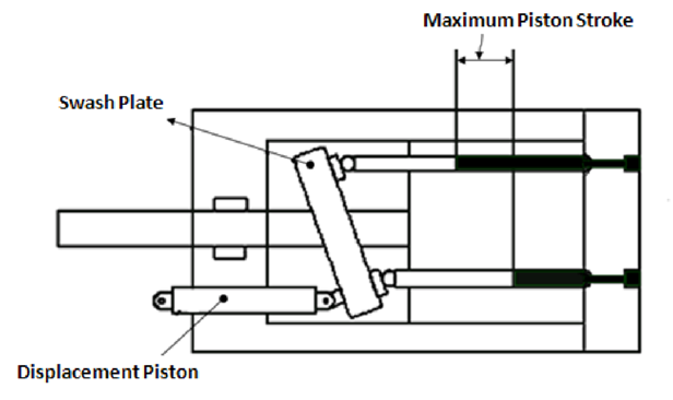
1.13.2 Swash-plate-type piston pump:
The schematic diagram of the swash plate type piston pump is shown in Fig.

In this type, the cylinder block and driveshaft are located on the same centerline. The pistons are connected to a shoe plate that bears against an angled swashplate.
As the cylinder rotates, the pistons reciprocate because the piston shoes follow the angled surface of the swashplate.
The outlet and inlet ports are located in the valve plate so that the pistons pass the inlet as they are being pulled out and pass the outlet as they are being forced back in.
This type of pump can also be designed to have a variable displacement capability. The maximum swash plate angle is limited to 17.5° by construction.
1.13.3 Radial Piston Pump:
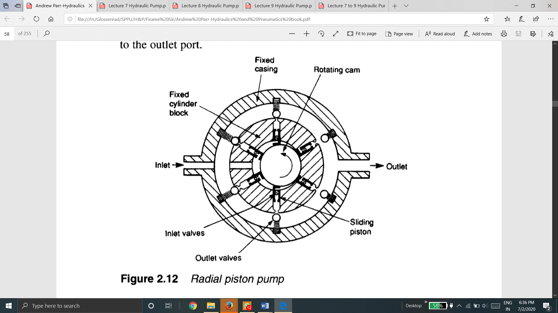
The figure shows one form of the radial piston pump.
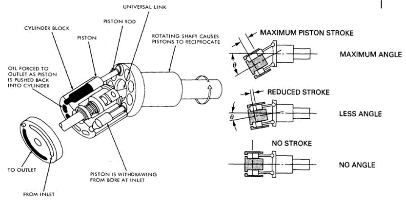
Fig. Radial Piston Pump
The pump consists of several hollow pistons inside a stationary cylinder block.
Each piston has spring-loaded inlet and outlet valves. As the inner cam rotates, fluid is transferred relatively smoothly from the inlet port to the outlet port.
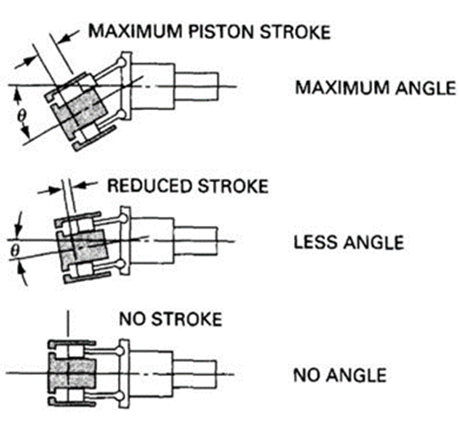
1.13.4 Volumetric Displacement and Theoretical Flow Rate of an Axial Piston Pump
The figure gives a schematic diagram of stroke change with respect to the offset angle.
Let
θ be an offset angle,
S the piston stroke in m,
D the piston circle diameter,
Y the number of pistons,
A the piston area in m2,
N the piston speed in RPM and
QT the theoretical flow rate in m3/min.
From fig,
tan θ = S/D
S = D x tan θ
The displacement volume of one piston = A x S m3
Total displacement volume of Y number of pistons = YAS m3
VD = YAS
From above equations we have,
VD = YAD tan θ m3/rev
Theoretical flow rate is
QT = DANY tan θ m3 /min
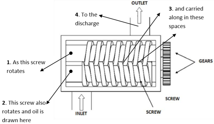
These pumps have two or more gear-driven helical meshing screws in a closefitting case to develop the desired pressure. These screws mesh to form a fluid-type seal between the screws and casing. A schematic diagram of a screw pump is shown in Fig.
A two-screw pump consists of two parallel rotors with inter-meshing threads rotating in a closely machined casing. The driving screw and driven screw are connected using timing gears.
Working
When the screws turn, the space between the threads is divided into compartments.
As the screws rotate, the inlet side of the pump is flooded with hydraulic fluid because of a partial vacuum.
When the screws turn in normal rotation, the fluid contained in these compartments is pushed uniformly along the axis toward the center of the pump, where the compartments discharge the fluid. Here the fluid does not rotate but moves linearly as a nut on threads.
Thus, there are no pulsations at a higher speed; it is a very quiet operating pump.
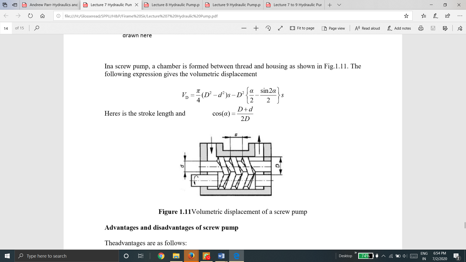
In a screw pump, a chamber is formed between thread and housing.
The following expression gives the volumetric displacement
Here s is the stroke length and
Advantages and disadvantages of screw pump
The advantages are as follows:
The disadvantages are as follows:
Pump capacity and working pressure help to determine the motor power required to drive the pump.
The definition of power is work per unit time
Power = | Work |
Time |
Power = | Force x Distance Travelled (by oil) |
Time |
Suppose a pump forces fluid along a pipe of area ‘A’ against pressure ‘P’ which moves fluid through a distance ‘x’ in time ‘t’.
Force = P A = Pressure x Area
Power = | P A x |
t |
But A x/t is a flow rate (Q = A V)
Power = Pressure x Flow Rate = P Q
When Pressure is in bar and flow rate in liters per min then,
Power = | P Q | KW |
600 |
1.15.1 Volumetric Efficiency: (ηV)
“It is the ratio of the actual flow rate of the pump to the theoretical flow rate of the pump.”
Volumetric Efficiency (ηV) = | The actual Flow rate of the pump |
The theoretical Flow rate of Pump | |
= | QA |
QT |
Volumetric efficiency (ηV) indicates the amount of leakage that takes place within the pump.
This is due to manufacturing tolerances and flexing of the pump casing under-designed pressure operating conditions.
For gear pumps, (ηV) = 80%–90%.
For vane pumps, (ηV) = 92%.
For piston pumps, (ηV) = 90%–98%.
1.15.2 Mechanical Efficiency: (ηm)
“It is the ratio of the pump output power assuming no leakage to actual power delivered to the pump.”
Mechanical Efficiency (ηm) = | Power output assuming no leakages |
Actual Power Delivered to pump | |
= | P QT |
TA N |
Where,
P is pump discharge pressure in Pa
QT is pump theoretical flow rate in m3/s
TA is Actual Torque delivered to pump in N-m
N is pump speed in rpm
Mechanical Efficiency can also be computed in terms of torques, as follows,
Mechanical Efficiency (ηm) = | Theoretical torque requirement for pump operations |
Actual torque Delivered to pump |
(ηm) = | Tth |
TA |
Tth = | Vd (m3) x P (Pa) | = | VdP | Nm |
2Π | 2Π |
And, TA = | 60 P |
2Π N |
1.15.3 Overall Efficiency: (ηo)
“It is defined as the ratio of actual power delivered by the pump to actual power delivered to the pump.”
Overall Efficiency (ηo) = | Actual Power delivered by the pump |
Actual Power delivered to Pump |
Overall efficiency considers all energy losses and can be also represented mathematically as follows:
(ηo) = (ηv) (ηm)
1.15.4 Numerical:
Example 1: A gear pump has an outside diameter of 82.6 mm, inside diameter of 57.2 mm, and a width of 25.4 mm. If the actual pump flow is 1800 RPM and the rated pressure is 0.00183 3 m /s, what is the volumetric efficiency?
Solution:
We have,
Outside diameter Do = 82.6mm
Inside diameter Di = 57.2 mm
Width d = 25.4mm
Speed of pump N = 1800 RPM
Actual flow rate = 0.00183 3 m /s
Theoretical flow rate


QT = 2.125  10-3
10-3
Volumetric efficiency is

Example 2: Determine the overall efficiency of a pump driven by a 10 HP prime mover if the pump delivers fluid at 40 LPM at a pressure of 10 MPa.
Solution:
Output Power = P Q
= 
= 6670 W
Input Power = 
Now, 
1.16.1 Pump Performance Curve
Pump performance characteristics are first analyzed independently of the rest of the hydraulic system and then as a part of the system. Both sets of data are valuable to the designer. Analyzing the pump by itself gives an indication of its capabilities and performance based on the speed of rotation, internal geometry, cost factors, etc., whereas analyzing pump performance in a system essentially determines pump system compatibility. In the first case, the system designer may observe performance curves to see if a specific pump has the pressure and volume flow rate to operate a given set of actuators. In a second instance, the system designer may be computing the noise, vibration, cavitation, and flow characteristics of a specific pump before or after installation to determine if the pump and existing system are compatible. Where the two are necessarily complementary, in practice much of hands-on work is completed independently. Pump performance characteristics are interpreted from data in tabular form and then graphed.
(a)
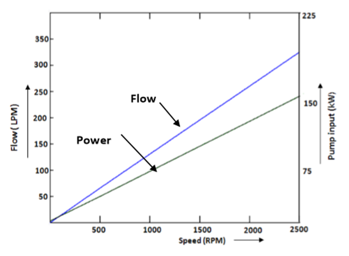
Figure (a) represents the relationship between input power and pump output flow of a variable displacement piston pump as a function of pump speed. Observe the linear relationship between the discharge flow and pump speed.

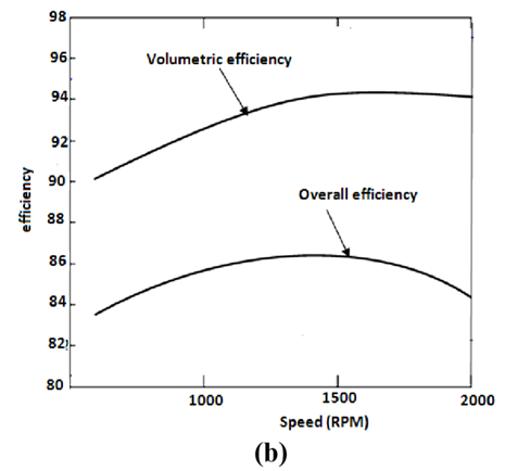
Figure (b) gives curves of overall and volumetric efficiencies as a function of speed.
(c)
The performance curves of the radial piston pump are given in Figure(c). The discharge flow of these pumps is nearly constant over a broad pressure range. Discharge flow can be varied infinitely between the point of inflection on the constant discharge portion of the curve and zero flow.
1.16.2 Pump Noise Characteristics
Pump noise is an important parameter used to determine the performance. Any increase in noise indicates increased wear and eventually pump failure. Pumps are good generators but poor radiators of noise. Noise is not just the sound coming directly from the pump, but also the vibration and fluid pulsation produced by the pump. Pumps are small in size and hence, they are poor radiators of noise. Reservoirs, electric motors, and piping being larger are better radiators. Hence, a pump-induced vibration can cause audible noise greater than that coming from the pump. Fixed displacement pumps are less noisy than variable displacement pumps because of their rigid construction.
Pump noise characteristics
References :
1. Pipenger J.J, Industrial Hydraulics, McGraw Hill
2. Pinches, Industrial Fluid Power, Prentice Hall
3. Yeaple, Fluid Power Design Handbook
4. Andrew A. Parr, Hydraulics and Pneumatics, Elsevier Science and Technology Books
5. ISO - 1219, Fluid Systems and components, Graphic Symbols
6. Standard Manufacturer’s Catalogues

