Unit 2
Actuators and Power Unit
Hydraulic systems are used to control and transmit power. A pump driven by a prime mover such as an electric motor creates a flow of fluid, in which the pressure, direction, and rate of flow are controlled by valves.
“An actuator is used to convert the energy of fluid back into mechanical power.”
The amount of output power developed depends upon the flow rate, the pressure drop across the actuator, and its overall efficiency. Thus, hydraulic actuators are devices used to convert the pressure energy of the fluid into mechanical energy.
Depending on the type of actuation, hydraulic actuators are classified as follows:
Hydraulic linear actuators, as their name implies, provide motion in a straight line. The total movement is a finite amount determined by the construction of the unit.
“The function of the hydraulic cylinder is to convert hydraulic power into linear mechanical force or motion.”
Hydraulic cylinders extend and retract a piston rod to provide a push or pull force to drive the external load along a straight-line path. Continuous angular movement is achieved by rotary actuators, more generally known as a hydraulic motor. Semi-rotary actuators are capable of limited angular movements that can be several complete revolutions but 360o or less is more usual.
Hydraulic cylinders are of the following types:
2.2.1 Single Acting Cylinder:
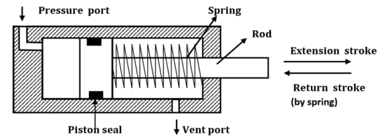
Fig. Single Acting Cylinder
According to the type of return, single-acting cylinders are classified as follows:
Gravity return Single Acting Cylinder:
The figure shows gravity-return-type single-acting cylinders.
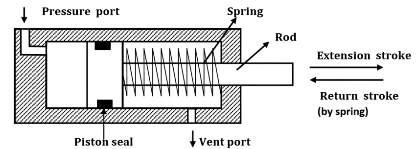
Fig. Gravity Return Single Acting Cylinder (a)push type (b)pull-type
Spring Return Single Acting Cylinder:
A spring-return single-acting cylinder is shown in Fig.
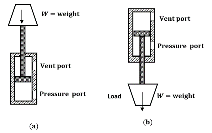
Fig. Spring Return Single Acting Cylinder (a)Push type (b)Pull type
2.2.2 Double Acting Cylinder
There are two types of double-acting cylinders:
Double Acting Cylinder with Piston Rod on one side
The figure shows the operation of a double-acting cylinder with a piston rod on one side.

(a)
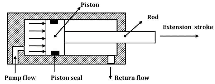
(b)
Fig. Double Acting Cylinder with piston rod on one side
Double Acting Cylinder with piston rod on both sides (Through-rod cylinders)
A double-acting cylinder with a piston rod on both sides (Fig.) is a cylinder with a rod extending from both ends. This cylinder can be used in an application where work can be done by both ends of the cylinder, thereby making the cylinder more productive. Double-rod cylinders can withstand higher side loads because they have an extra bearing, one on each rod, to withstand the loading.
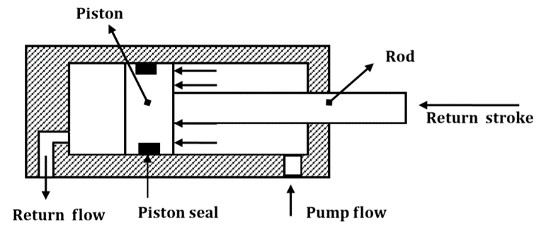
Fig. Double Acting Cylinder with piston rod on both sides
2.2.3 Telescopic Cylinder
A telescopic cylinder (shown in Fig.) is used when a long stroke length and a short retracted length are required.
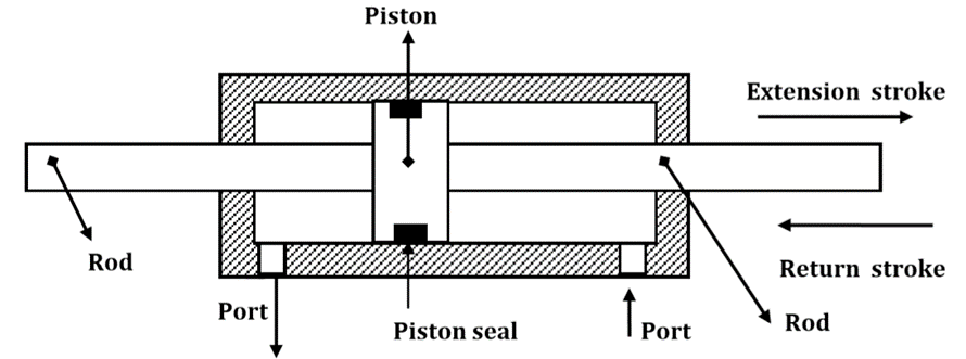
Fig. Telescopic Cylinder
The telescopic cylinder extends in stages, each stage consisting of a sleeve that fits inside the previous stage. One application for this type of cylinder is raising a dump truck bed. Telescopic cylinders are available in both single-acting and double-acting models.
2.2.4 Tandem Cylinder
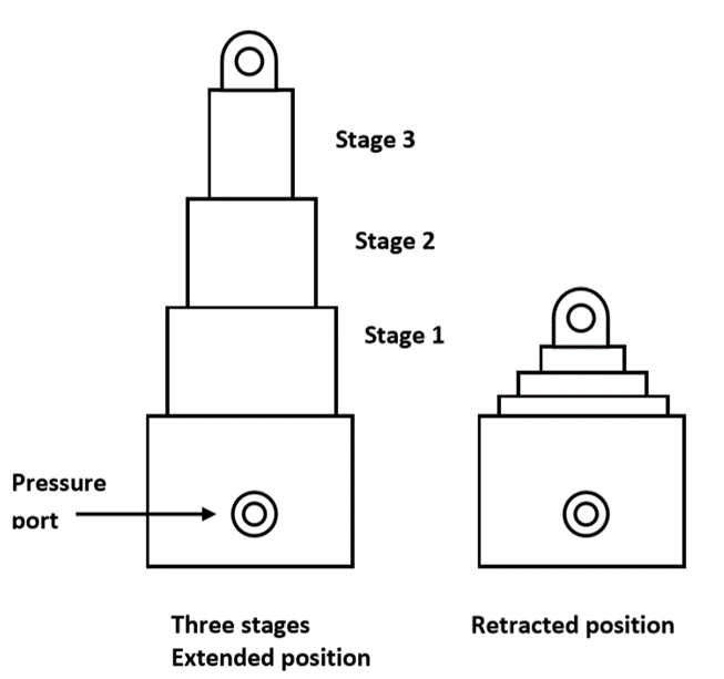
Fig. Tandem Cylinder
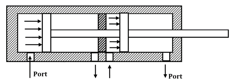
The output force (F) and piston velocity (v) of double-acting cylinders are not the same for extension and retraction strokes.
(a)

(b)
During the extension stroke shown in Fig(a), the fluid pressure acts on the entire circular piston area AP. During the retraction stroke, the fluid enters the rod-end side and the fluid pressure acts on the smaller annular area between the rod and cylinder bore (Ap−Ar) as shown by the shaded area in Fig(b) (Ar is the area of the piston rod). Due to the difference in the cross-sectional area, the velocity of the piston changes. Because Ap is greater than (Ap−Ar), the retraction velocity (vret) is greater than the extension velocity (vext) for the same flow rate.
During the extension stroke, the fluid pressure acts on the entire piston area (Ar), while during the retraction stroke, the fluid pressure acts on the annular area (Ap−Ar). This difference in the area accounts for the difference in output forces during extension and retraction strokes. Because Ar is greater than (Ap−Ar), the extension force is greater than the retraction force for the same operating pressure.
Force and velocity during extension stroke:
Velocity

Force

Force and velocity during the retraction stroke
Velocity 
Force
Power Developed by hydraulic cylinder
Power = Force x Velocity
In metric units, the kW power developed for either extension or retraction stroke is

Also,
Power during extension stroke is

Power during retraction stroke is

Comparing both equations, we can conclude that the powers during extension and retraction strokes are the same.
Hydraulic motors are rotary actuators. However, the name rotary actuator is reserved for a particular type of unit that is limited in rotation to less than 360o.
“A hydraulic motor is a device which converts fluid power into rotary power or converts fluid pressure into torque.”
Hydraulic motors can be classified as follows:
1. Gear motors.
2. Vane motors.
3. Piston motors:
- Gear motors:
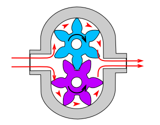
Fig. Hydraulic gear motor
2.4.2 Vane Motor
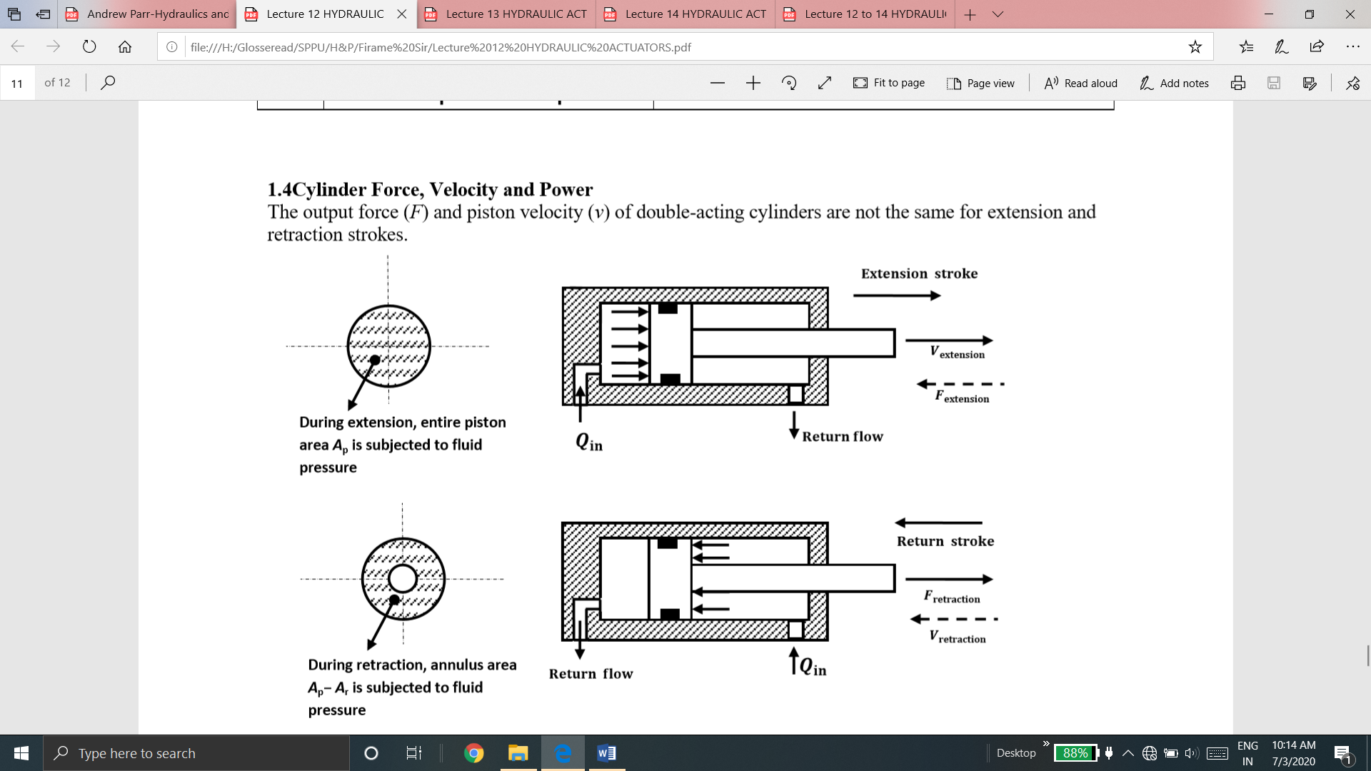
Fig.Unbalanced Hydraulic Vane Motor
The following figure shows the balanced vane motor.
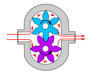
Fig. Balanced Hydraulic Vane Motor
2.4.3 Piston Type motor
Piston motors are classified into the following types:
2. Radial piston motors.
The figure illustrates the inline design in which the motor, driveshaft, and cylinder block are centered on the same axis.
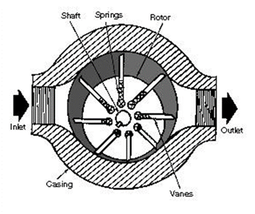
Fig. Swash-Plate Inline Piston Motor
b. Bent Axis Piston Motor
A bent-axis piston motor is shown in Fig.
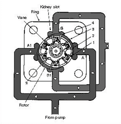
Fig. Bent-axis Piston Motor
B. Radial piston Motor
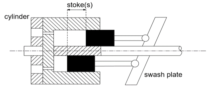
Fig. Radial Piston Motor
These are devices used to convert fluid energy into a torque which turns through an angle limited by the design of the actuator. With the majority of designs, the angle of rotation is limited to 360o although it is possible to considerably exceed this when using piston-operated actuators.
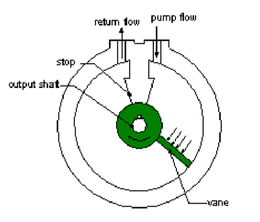
2.5.1 Vane-Type Semi-Rotary Actuator (Single Vane)
A single-vane rotary actuator is shown in Fig.
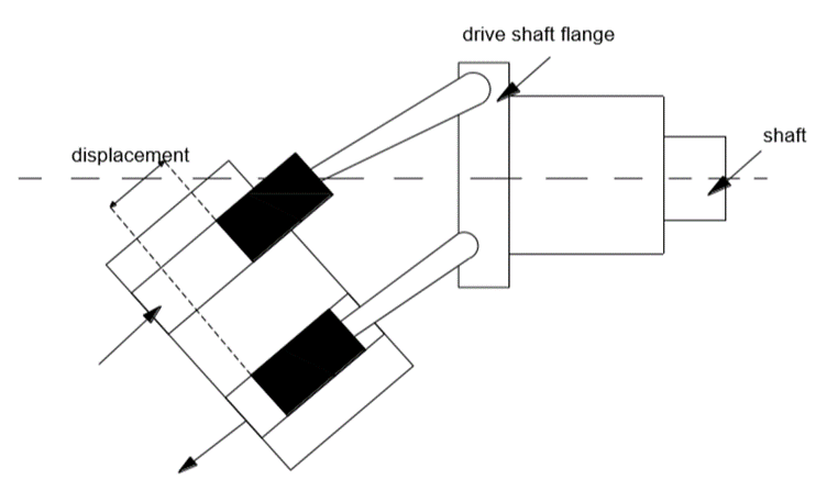
Fig. Vane Type Semi-Rotary Actuator
2.5.2 Two-Vane-Type Semi-Rotary Actuator
A two-vane rotary actuator is shown in Fig.
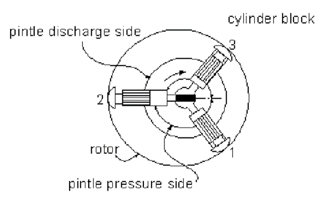
Fig. Two Vane Type Semi-Rotary Actuator
The performance of hydraulic motors depends upon many factors such as the precision of their parts, tolerances between the mating parts, etc. Internal leakage between the inlet and outlet affects the volumetric efficiency. Friction between mating parts affects the mechanical efficiency of a hydraulic motor. Gear motors typically have an overall efficiency of 70–75% as compared to vane motors which have 75– 85% and piston motors having 85–95%.
Motor torque is divided into three separate groups:
1. Starting torque: The starting torque is the turning force the motor exerts from a dead stop.
2. Running torque: Running torque is exerted when the motor is running and changes whenever there is a change in fluid pressure.
3. Stalling torque: Stalling torque is the torque necessary to stop the motor.
In most hydraulic motors, the stalling and starting torques are equal. Usually, starting torque is 75–80% of the maximum design torque.

2. Mechanical efficiency: The mechanical efficiency of a hydraulic motor is the ratio of actual work done to the theoretical work done per torque revolution. The output torque of a hydraulic motor is less than theoretical due to mechanical friction between the mating parts.

Here, theoretical torque and actual torque are given by


3. Overall efficiency: The overall efficiency of a motor is the ratio of output power to the input power of the motor. Output power is mechanical power output at the shaft and input power is fluid energy supplied to the inlet of the hydraulic motor.

The various kinds of mountings normally used in industries are as follows
It should be designed to give a limited amount of movement on one foot only to allow for thermal or load expansion. That is, the cylinder should be positively located or dowelled at one end only.
2. Rod-end flange or front flange mounting:
During the extended stroke, pressure in the hydraulic fluid acts on the cylinder-end cap, the force set up being transmitted to the front mounting flange through the cylinder body.
3. Rear flange, back flange or head-end flange mounting:
No stress is present in the cylinder owing to load on the extend stroke; only hoop stress is present. The load acts through the fluid onto the rear flange.
4. Trunnion mounting:
It allows angular movement. It is designed to take a shear load only. Bearing should be as close to the cylinder body as possible.
5. Eye or clevis mounting:
There is a tendency for the cylinder to jackknife under load. Sideloading of the bearing must be carefully considered.
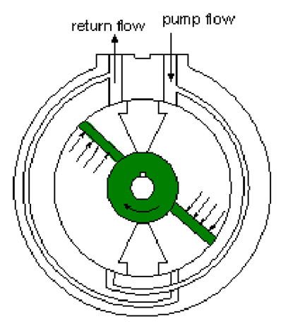
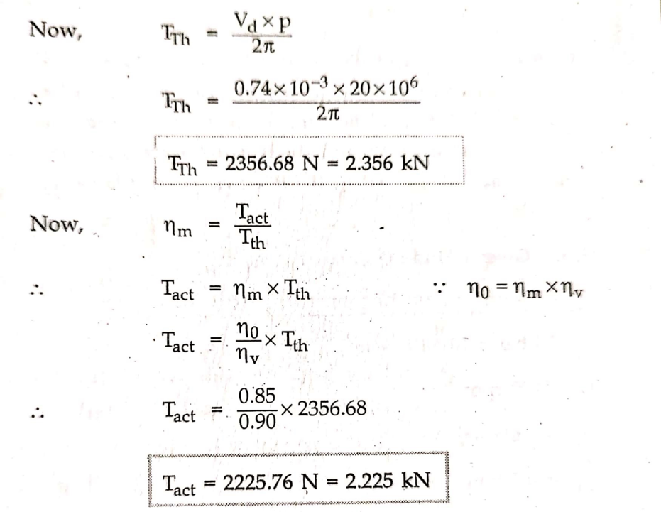
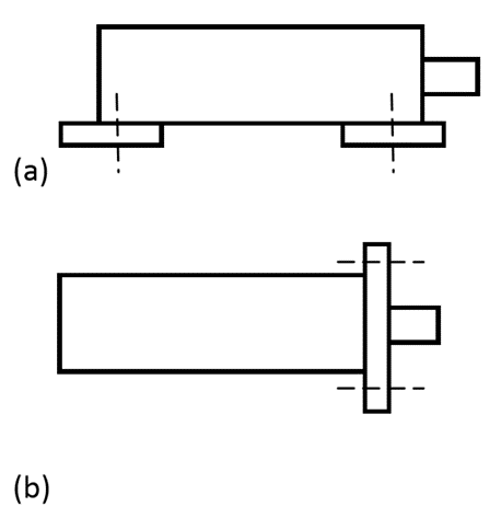
Fig. (a) Foot mounting; (b) rod-end flange or front flange mounting; (c) rear flange, back flange or head-end flange mounting; (d) trunnion mounting; (e) eye or clevis mounting.
A typical cushioning arrangement is shown in Fig.
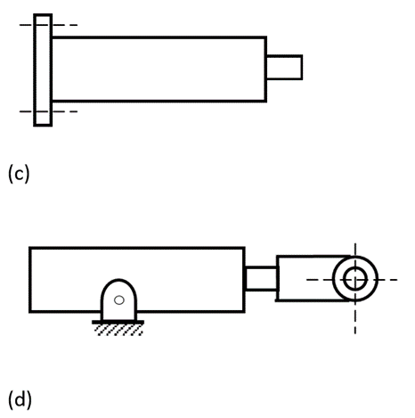
Fig. Hydraulic Cylinder with cushioning
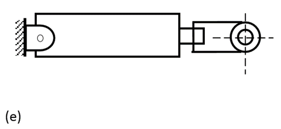
Fig. Operations of Cylinder Cushions
The hydraulic power unit is also termed as a hydraulic power pack.
The unit comprises of all those elements which are necessary to generate a pressurized fluid.
Mechanical energy is converted into hydraulic energy by using a pump that is driven by an electric motor.
Any power unit consists of the following components:
Types of power unit:
These power units are fixed at one location where no movement of the power unit is done. They are placed on a solid foundation and bolted to it so that it produces minimum vibration.
2. Portable Power unit:
These power units are called portable because they can be moved from one location to another. They are compact in size and easy to handle.
A reservoir is constructed with steel plates. The inside surface is painted with a sealer to prevent rust due to condensed moisture. At the bottom, it contains a drain plug to allow the complete drainage of the tank when required.
A removable head can be provided for easy access during cleaning. A vented breather cap is also included that contains an air filtering screen. This allows the tank to breathe as the oil level changes due to system demand requirements.
The functions of a fluid reservoir in a power hydraulic system are as follows:
2.10.1 Construction
Schematic diagram of the hydraulic reservoir is shown in Fig
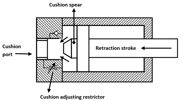
Fig. Hydraulic Reservoir
There are many components mounted on the reservoir and each one of them having specific features.
Following are the features of a hydraulic reservoir:
It should be airtight when closed but may contain the air vent that filters air entering the reservoir to provide a gravity push for proper oil flow.
It shows the level of oil in the reservoir without having to open the reservoir.
It is located lengthwise through the center of the tank and is two-third the height of the oil level. It is used to separate the outlet to the pump from the return line. This ensures a circuitous flow instead of the same fluid being recirculated. The baffle prevents local turbulence in the tank and allows foreign material to settle, get rid of entrapped air, and increase heat dissipation.
They are designed to enter the reservoir at points where air turbulence is the least. They can enter the reservoir at the top of the sides, but their ends should be near the bottom of the tank. If the return line is above the oil level, then returning oil can foam and draw in air.
It is usually a screen that is attached to the suction pipe to filter hydraulic oil.
It allows all oil to be drained from the reservoir. Some drain plugs are magnetic to help remove metal chips from the oil.
Strainers and filters are designed to remove foreign particles from the hydraulic fluid.
2.10.2 Types of Reservoirs:
Industrial reservoirs come in a variety of styles. Some of them are the following:
The reservoir may be vented to the atmosphere using an air filter or a separating diaphragm. The type most commonly used in industry, normally, has an air breather filter, although, in very dirty environments, diaphragms or airbags are used.
2. Pressurized:
A pressurized reservoir usually operates between 0.35 and 1.4 bar and has to be provided with some method of pressure control; this may be a small air compressor maintaining a set charge pressure. In motor circuits where there is a little change in fluid volume in the reservoir, a simple relief valve may be used to limit the air pressure that alters with changes in temperature. The advantages of a pressurized reservoir are that it provides boost pressure to the main pump and prevents the ingress of atmospheric dirt.
2.11.1 Seals
“Seals are used in hydraulic systems to prevent excessive internal and external leakage and to keep out contamination.”
Various functions of seals include the following:
Classification of hydraulic seals
1. According to the method of sealing:
2. According to the relative motion existing between the seals and other parts:
3. According to geometrical cross-section:
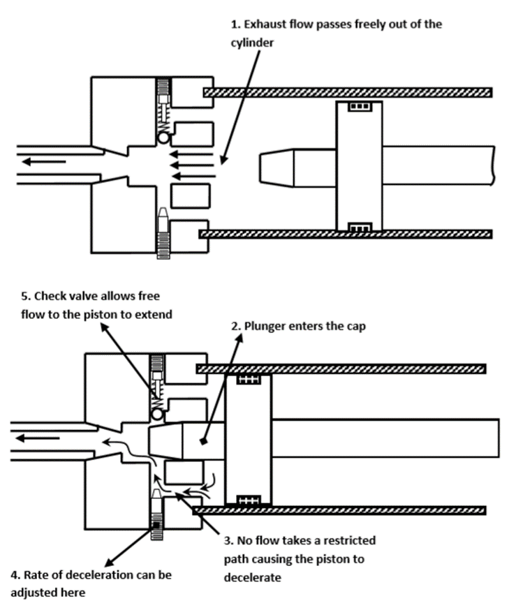
Fig. O-ring
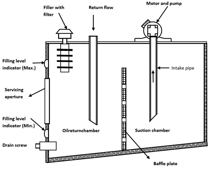
Fig. V-ring and U-ring Seal
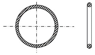
Fig. T-ring seal
4. According to the type of seal material used
2.11.2 Filters and Strainers
They are devices whose primary function is the retention, by some fine porous medium, of insoluble contaminants from the fluid. Filters are used to pick up smaller contaminant particles because they can accumulate them better than a strainer. Generally, a filter consists of fabricated steel housing with an inlet and an outlet. The filter elements are held in position by springs or other retaining devices. Because the filter element is not capable of being cleaned, that is, when the filter becomes dirty, it is discarded and replaced by a new one. Particle sizes removed by filters are measured in microns. The smallest sized particle that can be removed is as small as 1 µm. A strainer is a device whose function is to remove large particles from a fluid using a wire screen. The smallest sized particle that can be removed by a strainer is as small as 0.15 mm or 150 µm.
2. Hydraulic strainers:
A strainer is a coarse filter. Fluid flows more or less straight through it. A strainer is constructed of a fine wire mesh screen or screening consisting of a specially processed wire of varying thickness wrapped around metal frames. It does not provide as fine a screening action as filters do, but offers less resistance to flow and is used in pump suction lines where pressure drop must be kept to a minimum. A strainer should be as large as possible or wherever this is not practical, two or more may be used in parallel.
“A hydraulic accumulator is a device that stores the potential energy of an incompressible fluid held under pressure by an external source against some dynamic force.”
This dynamic force can come from different sources. The stored potential energy in the accumulator is a quick secondary source of fluid power capable of doing useful work.
There are three basic types of accumulators:
2.12.1 Weight-loaded or gravity accumulator:
The schematic diagram of the weight loaded accumulator is shown in Fig.

Fig. Dead Weight Accumulator
2.12.2 Spring-loaded Accumulator
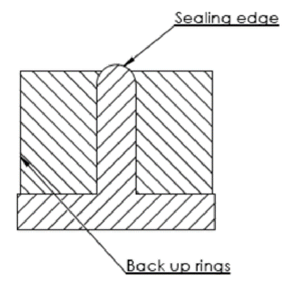
Fig. Spring-loaded Accumulator
2.12.3 Gas loaded Accumulator
A gas-loaded accumulator is popularly used in industries. Here the force is applied to the oil using compressed air.
There are two types of gas-loaded accumulators:
Non-separator-type accumulator:
Here the oil and gas are not separated. Hence, they are always placed vertically.
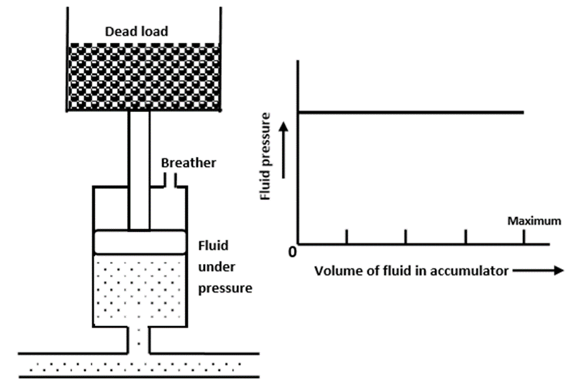
Fig. Non-separator Type Accumulator
Separator-type accumulator:
Here the oil and gas are separated by an element.
Based on the type of element used to separate the oil and gas, they are classified as follows:
It consists of a cylinder with a freely floating piston with proper seals. Its operation begins by charging the gas chamber with a gas (nitrogen) under a pre-determined pressure. This causes the free sliding piston to move down. Once the accumulator is pre-charged, hydraulic fluid can be pumped into the hydraulic fluid port. As the fluid enters the accumulator, it causes the piston to slide up, thereby compressing the gas that increases its pressure and this pressure is then applied to the hydraulic fluid through the piston.
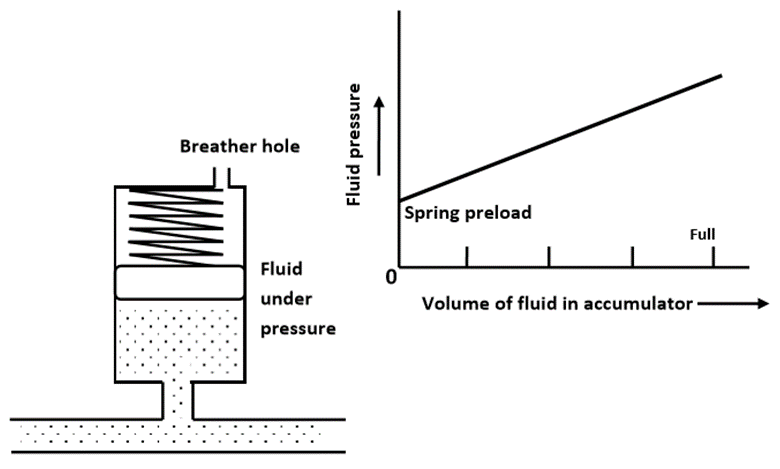
Fig. Piston Type Accumulator
II. Diaphragm accumulator
In this type, the hydraulic fluid and nitrogen gas are separated by a synthetic rubber diaphragm.
The advantage of a diaphragm accumulator over a piston accumulator is that it has no sliding surface that requires lubrication and can, therefore, be used with fluids having poor lubricating qualities. It is less sensitive to contamination due to the lack of any close-fitting components.
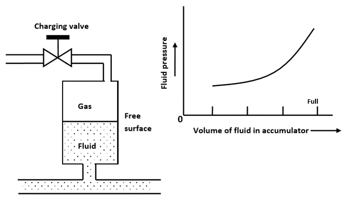
Fig. Diaphragm-type Accumulator
III. Bladder accumulator
It functions in the same way as the other two accumulators.
Here the gas and the hydraulic fluid are separated by a synthetic rubber bladder. The bladder is filled with nitrogen until the designed pre-charge pressure is achieved. The hydraulic fluid is then pumped into the accumulator, thereby compressing the gas and increasing the pressure in the accumulator. The port cover is a small piece of metal that protects the bladder from damage as it expands and contacts the fluid port.
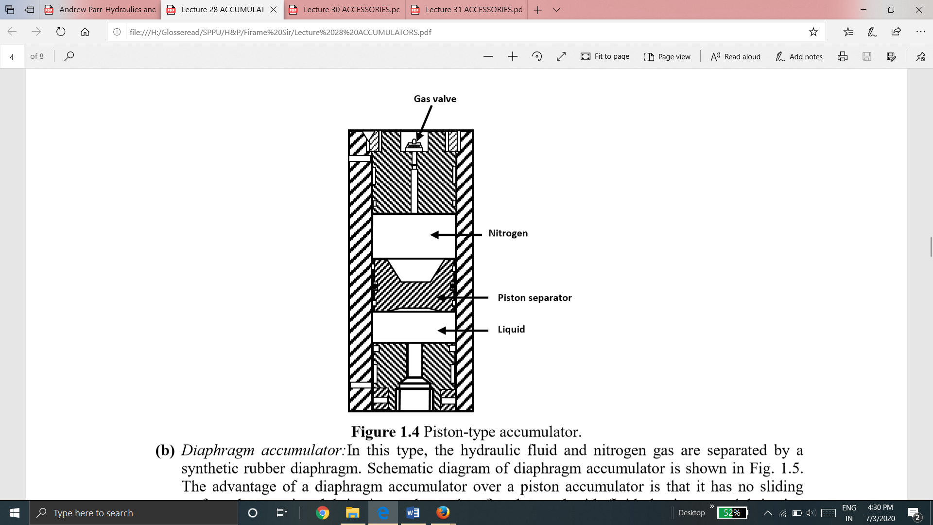
Fig. Bladder-type Accumulator
2.12.4 Sizing of Accumulator for isothermal conditions
For isothermal condition, the Boyle–Mariotte law can be rewritten in terms of V1 and V2 as


The difference between V1 at the minimum operating pressure P1 and V2 at the maximum operating pressure P2 gives the amount of the stored fluid . Thus,


In the above equations, V1 and V2 are nitrogen volumes at the pressures P1 and P2, and V0 is the nitrogen pre-charge volume at the pressure P0 in liters. It is the maximum volume of gas that can be stored in the accumulator.
2.12.5 Sizing of Accumulators for Adiabatic Condition
Starting from the basic formula,

it can be shown that for adiabatic conditions, the values of maximum nitrogen volume V0 at the pre-charge pressure P0 and the stored volume of oil are given by the following equations:

“A hydraulic intensifier is a hydraulic machine for transforming hydraulic power at low pressure into a reduced volume at higher pressure.”
A hydraulic intensifier is a device that is used to increase the intensity of pressure of any hydraulic fluid or water, with the help of the hydraulic energy available from a huge quantity of water or hydraulic fluid at low pressure.
These devices are very important in the case of hydraulic machines, mainly hydraulic presses, which require water or hydraulic fluid at very high pressure which cannot be obtained from the main supply directly.
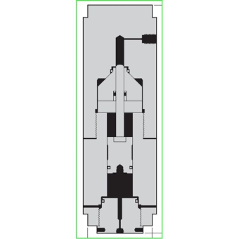
Fig. Hydraulic Intensifier
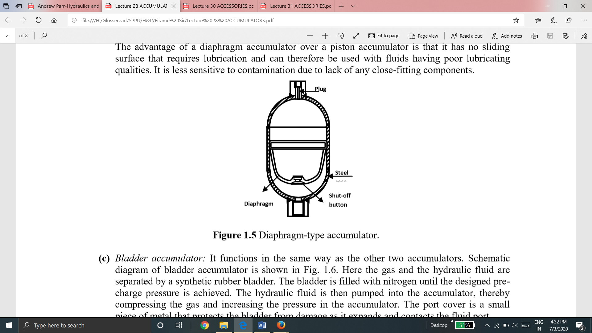
Fig. Application of Hydraulic Intensifier
In a hydraulic system, due to pumping action heat is generated. The temperature affects oil viscosity. Such changes are viscosity are not desirable in hydraulics. Thus temperature switches are used to measure the amount of heat energy that is generated by a system and take appropriate action when the temperature goes beyond or below the set value.
There are four commonly used temperature sensor types:
1. Negative Temperature Coefficient (NTC) thermistor
A thermistor is a thermally sensitive resistor that exhibits a large, predictable, and precise change in resistance correlated to variations in temperature. An NTC thermistor provides a very high resistance at low temperatures. As temperature increases, the resistance drops quickly. Because an NTC thermistor experiences such a large change in resistance per °C, small changes in temperature are reflected very fast and with high accuracy (0.05 to 1.5 °C). Because of its exponential nature, the output of an NTC thermistor requires linearization. The effective operating range is -50 to 250 °C for glass encapsulated thermistors or 150°C for standard.
2. Resistance Temperature Detector (RTD)
An RTD, also known as a resistance thermometer, measures temperature by correlating the resistance of the RTD element with temperature. An RTD consists of a film or, for greater accuracy, a wire wrapped around a ceramic or glass core. The most accurate RTDs are made using platinum but lower-cost RTDs can be made from nickel or copper. However, Nickle and copper are not as stable or repeatable. Platinum RTDs offer a highly accurate and fairly linear output (0.1 to 1 °C) across -200 to 600 °C. While providing the greatest accuracy, RTDs also tend to be the most expensive of temperature sensors.
3. Thermocouple
This temperature sensor type consists of two wires of different metals connected at two points. The varying voltage between these two points reflects proportional changes in temperature. Thermocouples are nonlinear, requiring conversion when used for temperature control and compensation, typically accomplished using a lookup table. Accuracy is low, from 0.5 °C to 5 °C. However, they operate across the widest temperature range, from -200 °C to 1750 °C.
4. Semiconductor-based sensors
A semiconductor-based temperature sensor is placed on integrated circuits (ICs). These sensors are effectively two identical diodes with temperature-sensitive voltage vs current characteristics that can be used to monitor changes in temperature. They offer a linear response but have the lowest accuracy of the basic sensor types at 1 °C to 5 °C. They also have the slowest responsiveness (5 s to 60 s) across the narrowest temperature range (-70 °C to 150 °C).
References :
1. Pipenger J.J, Industrial Hydraulics, McGraw Hill
2. Pinches, Industrial Fluid Power, Prentice Hall
3. Yeaple, Fluid Power Design Handbook
4. Andrew A. Parr, Hydraulics and Pneumatics, Elsevier Science and Technology Books
5. ISO - 1219, Fluid Systems and components, Graphic Symbols
6. Standard Manufacturer’s Catalogues