Unit 6
System Analysis and Design
Depending upon purpose of operations, the hydraulic cylinder may be subjected to various accelerations or decelerations steps. The piston of cylinder is accelerated to reduce cycle time that means to minimize idle time and the piston of cylinder is decelerated to reduce impact loads and provides proper cushioning.
The following equations are used to study the dynamics of piston-cylinder mechanisms.


Following equation is used to find out the thrust or force generated

The other element which also plays a role in dynamics of piston and cylinder mechanics are the load inertia, seal friction, load friction, etc.
Dynamic thrust = 0.9 x Static thrust
6.2 Hydraulic Forces/Thrust, Pressures and velocities under static and dynamic applications, considering friction and inertia loads.
Figure shows the various force generated in the cylinder
Let,
Fp = Hydraulic Force Available for work
Fb = Back Pressure force
Ff = Frictional force generated
Fd = Dynamic Force
For smooth working,

m.a = Inertia force
m.g = Gravity Force
Hydraulic Force = Static Force + Dynamic Force
Friction Force
Seal and packing friction causes major loss of useful hydraulic force.
Let,
Ac = Circumferential Area of seal = 
D = diameter of piston or inner diameter of cylinder
P = pressure of oil
µ = coefficient of friction
Fpre = Pre-load applied on seal
The friction force can be given as

Effective force
The cylinder force available for operation is called as effective force.
Effective force is some percent of theoretical force

Therefore, effective force is given as

The pressure drop inside the cylinder is given by,

 Total Pressure drop
 Pressure drop in inlet line/ pressure line

This is by considering a double acting cylinder.
Flow Velocities
Let,
Vf = Velocity of piston for forward stroke
Vr = Velocity of piston for return stroke
Qp = Pump flow rate
Velocity of piston during forward stroke can be calculated as

Velocity of piston during return stroke can be calculated as

Example
An 8 cm diameter hydraulic cylinder has a 4 cm diameter rod. If the cylinder receives flow at 100 LPM and 12 MPa, find the (a) extension and retraction speeds and (b) extension and retraction load carrying capacities.
Solution
Let us first convert the flow in LPM to  before we calculate forward velocity
  =100
=100
LPM=100/(1000*60)=1/600
Now
DC= diameter of cylinder =8cm =8*
 =diameter of piston rod=4cm=4*
P=12MPa=12* N/
N/ or Pa
or Pa
(a) Forward velocity is given by

Return velocity is given by

(b) Force extension is given by

Force during retraction is given by
fret=p(Ap-AR)

=42238.9N=45.24 KN
There are so many factors involved in sealing elements working principle. Ignoring any of these factors could increase the possibility of a design mistake. Hydraulic cylinders have different working conditions. For example, the cylinder used in injection machine and loader both have different seal design criteria in terms of material and sealing elements.
Four main variables should be taken into account while choosing a sealing element.
1. Temperature:
Media and working condition temperature should be considered when choosing suitable sealing element.
2. Pressure:
System pressure and pressure type should be considered when choosing suitable sealing element.
3. Sliding Speed:
System sliding speed should be considered when choosing suitable sealing element.
4. Media:
Media type should be considered when choosing suitable sealing element.
The technical values related to these 4 main variables can be found in our technical catalogue for each sealing element. Apart from these 4 main criteria, there are other variables which also affect the working of hydraulic cylinders. Alp Seals consider these following conditions to be the most important ones.
5. Working Conditions
This is one of the most important variables for hydraulic cylinder design. There are so many factors on this stage which deserve attention.
Main factors are as follows;
To analyze the given circuit, following steps are followed
Step I: Draw circuit diagram as it is
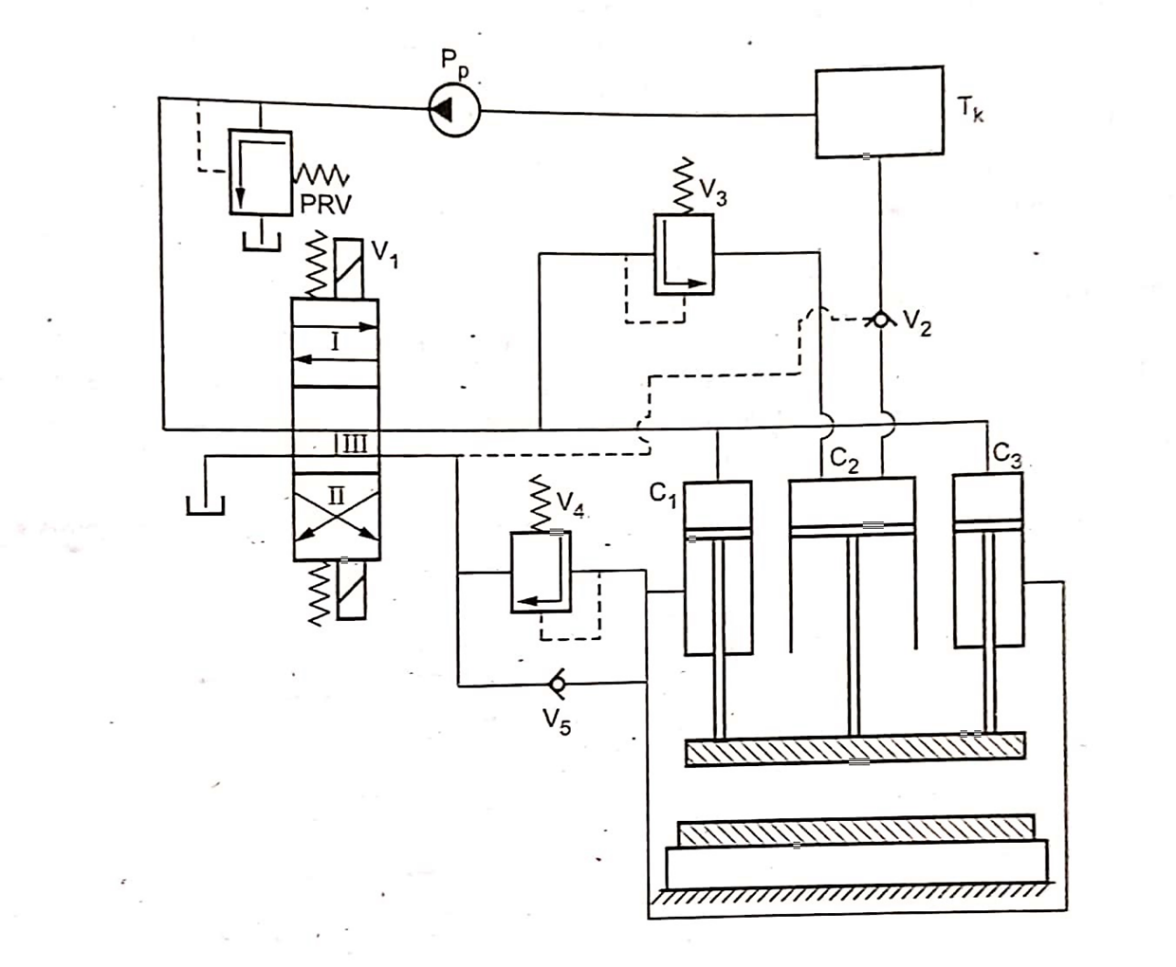
Step II: label the circuit diagram
Step III: List the components
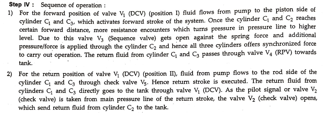
Step IV: Explain the sequence of operation
Example
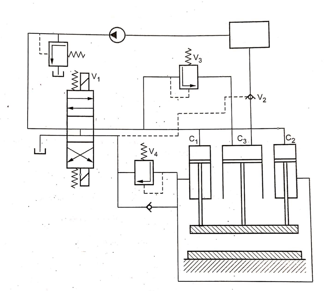
Analyze the given hydraulic circuit.

Solution
Step I: Drawing the circuit
StepII: Labelling

Sr.no. | component | Notation used | Specification/function |
1. | Tank |
| To store hydraulic oil |
2. | pump |
| To pressurize hydraulic oil .
|
3. | Pressure relief valve |
| Normally closed valve , opens when system pressure crosses set limit |
4. | Direction control valve |
| 4/3 spring centered ,solenoid operated directional control valve |
5. | Check valve (pilot operated) |
| Restrict flow in one direction and allows in other |
6. | Sequence valve |
| Start operation two once operation one is over .
|
7. | cylinder |
| Double acting cylinder. |

The components are selected from manufacturer’s catalogue, which is given below:
1) Suction Strainer
It is selected on the basis of capacity in terms of liters per minute (lpm).
Model | Flow Capacity (lpm) |
S1 | 38 |
S2 | 76 |
S3 | 152 |
2) Oil Reservoir
The oil reservoir is selected on the basis of storage capacity required for particular operation
One can select the reservoir capacity 2 to 3 times the max flow rate. Generally it is min 4 times the max flow rate.
Model | Capacity (lit.) |
T1 | 40 |
T2 | 100 |
T3 | 250 |
T4 | 400 |
T5 | 600 |
3) Pressure gauges
Pressure gauge is to be selected on the basis of working pressure.
Range is to be twice the working pressure.
Model | Range (bar) |
PG1 | 0-25 |
PG2 | 0-40 |
PG3 | 0-100 |
PG4 | 0-160 |
4) Selection of pump
The hydraulic pump is selected on the basis of the pressure to be generated and the flow rate or delivery of the pump.
Model | Pressure (bar) | Delivery (m3/sec) |
P1 | 65 | 12 x 10-3 |
P2 | 75 | 2 x 10⁻³ |
P3 | 75 | 6 x 10⁻³ |
In case of vane pump, following table is selected
Model | Delivery (lpm) | ||
At 0 bar | At 35 bar | At 70 bar | |
P1 | 8.5 | 7.1 | 5.3 |
P2 | 12.9 | 11.4 | 9.5 |
P3 | 17.6 | 16.1 | 14.3 |
P4 | 25.1 | 23.8 | 22.4 |
P5 | 39 | 37.5 | 35.6 |
5) Pressure relief valve
Pressure relief valve are chosen on the basis of the working pressure and the flow rate of the pump.
Model | Flow range (lpm) | Max working pressure (bar) |
R1 | 11.4 | 70 |
R2 | 19 | 210 |
R3 | 30.4 | 70 |
R4 | 57 | 105 |
6) Flow control valves
Selected on the basis of max working pressure and flow range
Model | Max working pressure (bar) | Flow Range (lpm) |
F1 | 70 | 0-4.1 |
F2 | 105 | 0-4.9 |
F3 | 105 | 0-16.3 |
F4 | 70 | 0-24.6 |
7) Direction control valve
Selected on the basis of max working pressure and flow capacity.
Model | Max working Pressure (bar) | Flow Capacity (lpm) |
D1 | 350 | 19 |
D2 | 210 | 38 |
D3 | 210 | 76 |
8) Check Valve
Selected on the basis of max working pressure and flow capacity.
Model | Max working Pressure (bar) | Flow Capacity (lpm) |
C1 | 210 | 15.2 |
C2 | 210 | 30.4 |
C3 | 210 | 76 |
9) Pilot operated check valve/sequence valve
Selected on the basis of max working pressure and flow capacity.
Model | Max working Pressure (bar) | Flow Capacity (lpm) |
PO1 | 210 | 19 |
PO2 | 210 | 38 |
PO3 | 210 | 76 |
10) Cylinder (maximum working pressure: 210 bar)
Selected on the basis of rod diameter and bore diameter.
Increasing bore diameter, cylinder becomes safe but also bulky.
Model | Bore Diameter (mm) | Rod Diameter (mm) |
A1 | 25 | 12.5 |
A2 | 40 | 16 |
A3 | 50 | 35 |
A4 | 75 | 45 |
A5 | 100 | 50 |
11) Motor
Selected on the basis of Pressure and volume displacement.
Model | Pressure (bar) | Volume Displacement (m3/rev) |
M1 | 70 | 0.5 x 10⁻⁴ |
M2 | 70 | 2 x 10⁻⁴ |
M3 | 70 | 5 x 10⁻⁴ |
Note: Prefer the selection on the basis of capacity.
Step I: Design of cylinder

Calculate Ap from the above formula
And find the diameter of piston using

Select the model corresponding to the piston diameter.
Sometimes, pressure is not mentioned in the problem, so in such cases, select the model of cylinder firstly and then calculate the working pressure.
Step II: Flow rate / Discharge
From the given condition calculate the velocities of the extension stroke. Stroke may be divided into different parts giving different velocities.
Select the maximum velocity to calculate the flow rate.

This flow rate must be considered for further calculations.
Step III: Repeat the same calculation for return stroke

and


From the above formulas calculate max working pressure and flow rate for return stroke.
Now, for selecting the components, consider
Step IV: Calculate power
Calculate power considering max Q and max p

Step V: Selecting other components
From the above calculated values, select the other components by using manufacturer’s catalogue given in section 6.5.
Example:
A machine slide is moved by means of hydraulic cylinder. The motion of the cylinder is as follows,
a) Initially it moves through a distance of 250 mm against a load at 15000N in about 5 sec.
b) It is followed by a working stroke of 100 mm against an effective load of 35000 N. The feed rate during this part of stroke is required to be between 0.5 to 1 m/min.
c) The return stroke is to be as fast as possible.
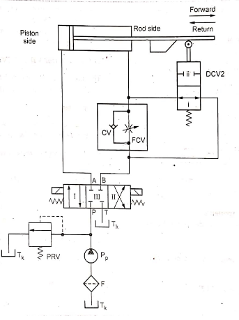
A meter-out circuit is to be used. Draw a circuit which will fulfil these requirements.
Solution:
Step-1
First meter-out circuit need to be usedv and forward stroke is split two parts.
Step-11: Design stage
Given  ,
,  ,
,
 ,
, 
A Calculation for forward stroke:
It is mentioned in the problem that initial movement during forward stroke is through a distance of 250mm against the load of 15kN in 5 seconds. So extension speed will be,


The second part of the forward stroke is through 100mm against the effective load of 35000N. The feed rate is 0.5 to 1 m/min. For safer side taking higher feed rate which is 1m/min.

Selection:- Selecting model “A5” of cylinder for getting highest safety.
From data given,
Bore diameter=piston diameter= =100mm
Rod diameter=
Now, calculating pressure and flow rate for both part of forward stroke,

a) For first part of stroke:


Flow rate for this part,


b) For second part of stroke:


Flow rate for this part,


B) Calculation for return stroke:
In order to calculate return speed (which is as fast as possible), the maximum flow rate from forward stroke is considered.

Also for return stroke effective area for pressure will be 


From this we can calculate the time required for the return stroke to cover 350mm(250+100) distance.


Time=5.24sec
Put the maximum working pressure and maximum flow rate(discharge) together.
System parameters:
a) Maximum working pressure:
 (during second part of forward stroke)
b) Maximum flow rate:


(during first part of forward stroke)
From above, let us calculate the power required by the system,
Power=P=p*Q


Step-III Selection of components
Following are the model selected from the design,
1) Oil reservoir: Model:T2:
By thumb rule, reservoir capacity should be 2 to 3 times the maximum flow rate.


Capacity 70.68 liters
So T2 model is selected,
2) Solution strainer: Model:S1:
From maximum flow rate of 23.56 lpm, we select the model S1.
3) Hydraullic pump: Model:P5:
From the table 16.4 (b), selecting model for P5, for the flow rate of 35.6 lpm at the pressure of 70 bar.
4) Directional Control Valve (DCV): Model:D2:
Both the DCV’s used are selected from Table 16.7 on the basis of working pressure (44.56 bar) and maximum flow rate (23.56 lpm). So selected model is D2.
5) Pressure Relief Valve (PRV): Model: R3:
The satisfying model of pressure relief valve is R3 which is selected from table 16.5
6) Flow Control Valve: Model:F4:
The flow control valve satisfying the system conditions is selected from Table 16.6. The model selected is F4.
7) Cylinder:Model:A5:
The cylinder model “A5” is already selected, considering safety aspect.
Finally you can put the selected models in tabular form:
Component | Model selected | Model Capacity |
Oil reservoir | T2 | 100 lit. |
Suction strainer | S1 | 38 lpm |
Hydraullic pump | P5 | 35.6 lpm, 70 bar |
Directional control valve | D2 | 38 lpm, 210 bar |
Pressure control valve | R3 | 30.4 lpm, 70 bar |
Flow control valve | F4 | 0-24.6 lpm, 70 bar |
Cylinder | A5 |
|


