UNIT 1
INTRODUCTION AND THERMAL POWER PLANT
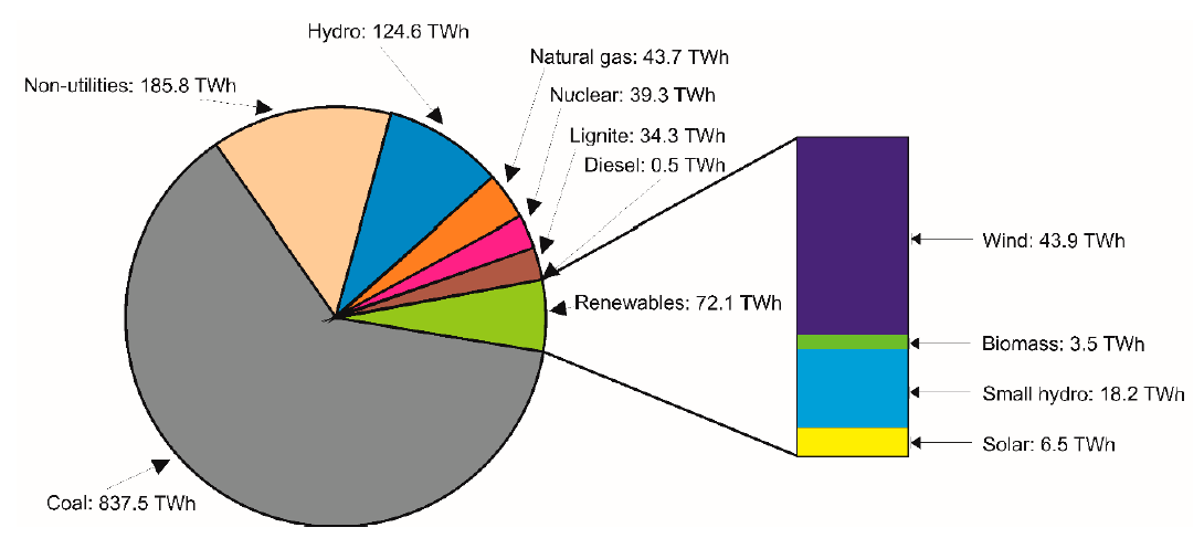
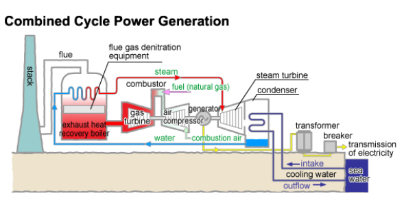
This figure below explains the status very well.
1.3 Role of private and governmental organizations
Electricity is an essential requirement and need for all facets of our life. It is a critical infrastructure on which the socio-economic development of the country depends. Supply of electricity at reasonable rate to rural India is essential for its overall development. Equally important is availability of reliable and quality power at competitive rates to Indian industry to make it globally competitive and to enable it to exploit the tremendous potential of employment generation.
Electricity is a commodity that cannot be stored in the grid where demand and supply have to be continuously balanced. The widely distributed and rapidly increasing demand requirements of the country need to be met in an optimum manner.
Electricity Act, 2003 provides an enabling framework for accelerated and more efficient development of the power sector. The Act seeks to encourage competition with appropriate regulatory intervention. Competition is expected to yield efficiency gains and in turn result in availability of quality supply of electricity to consumers at competitive rates.
The National Electricity Policy aims at laying guidelines for accelerated development of the power sector, providing supply of electricity to all areas and protecting interests of consumers and other stakeholders keeping in view availability of energy resources, technology available to exploit these resources, economics of generation using different resources, and energy security issues.
The National Electricity Policy has been evolved in consultation with and taking into account views of the State Governments, Central Electricity Authority (CEA), Central Electricity Regulatory Commission (CERC) and other stakeholders.
A carbon credit is a permit or certificate allowing the holder, such as a company, to emit carbon dioxide or other greenhouse gases. The credit limits the emission to a mass equal to one ton of carbon dioxide. The ultimate goal of carbon credits is to reduce the emission of greenhouse gases into the atmosphere.
A carbon credit is fundamentally a permit—issued by a government or other regulatory body—that allows its holder to burn a specified amount of hydrocarbon fuel over a specified period. Each carbon credit is valued against one ton of hydrocarbon fuel. Companies or nations are allotted a certain number of credits and may trade them to help balance total worldwide emissions. "Since carbon dioxide is the principal greenhouse gas," the United Nations notes, "people speak simply of trading in carbon."
It includes:
The primary function of transmission and distribution equipment is to transfer power economically and reliably from one location to another.
Conductors strung on towers and poles carry the high-voltage, AC electric current. A large number of copper or aluminum conductors in the form of wires and cables are used to form the transmission path.
The resistance of the long-distance transmission conductors is to be minimized. Energy loss in transmission lines is wasted in the form of I2R losses. The power factor is corrected with the help of capacitors.
Transformers are placed at strategic locations throughout the system to minimize power losses in the T&D system. They are used to change the voltage level from low-to-high in step up transformers and vice versa.
The power source to end user energy efficiency link is a key factor, which influences the energy input at the source of supply.
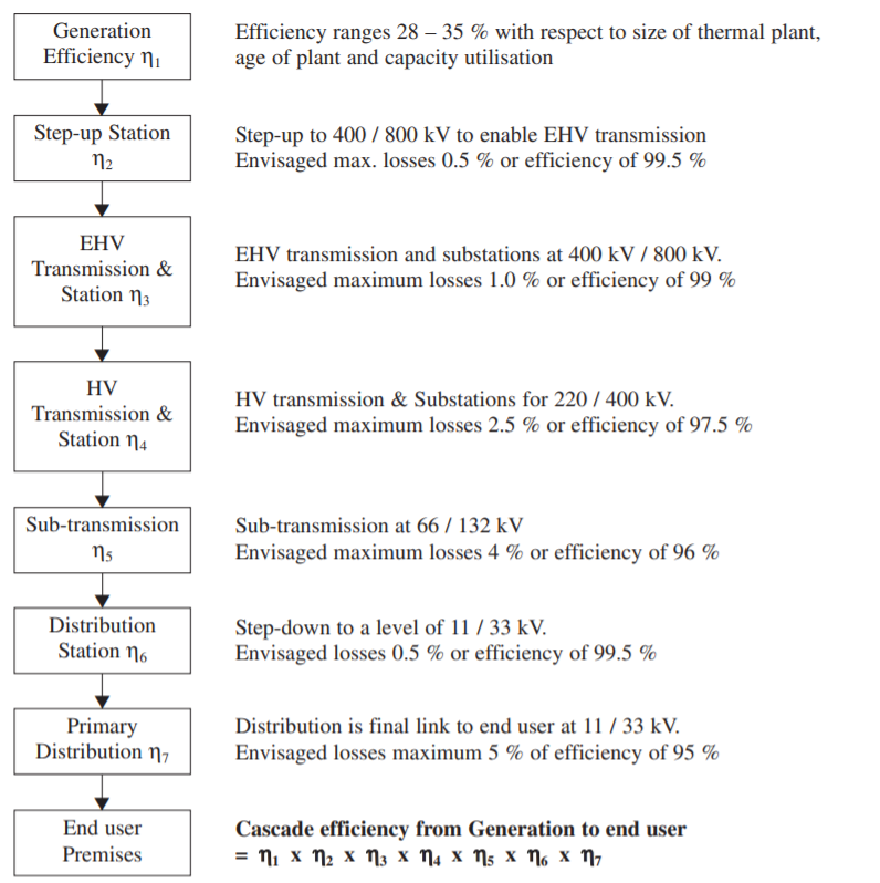
If we consider the electricity flow from generation to the user in terms of cascade energy efficiency, typical cascade efficiency profile from generation to 11 – 33 kV user industry will be as below:
1.8 Thermal Power Plant : General layout of modern thermal power plant with different circuits
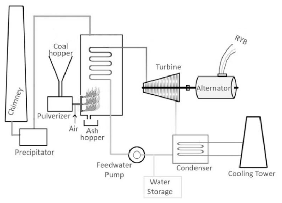
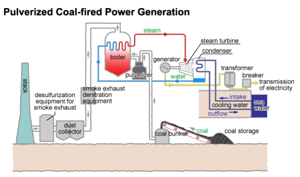
In power stations, steam is produced by burning some fossil fuel (e.g. coal) and then used to run a steam turbine. Hence, sometimes called as a Steam Power Station. After the steam passes through the steam turbine, it is condensed in a condenser and again fed back into the boiler to become steam. This is known as ranking cycle.
Coal: Bituminous coal is used as fuel. The coal is stored in either 'dead storage' or in 'live storage'. Dead storage is generally 40 days backup whereas Live storage is a raw coal bunker in boiler house. The coal is cleaned to filter out iron particles are present in a magnetic cleaner which may damage the equipment. The coal from live storage is first crushed and then converted into powdered form. It undergoes complete combustion, and also improves efficiency of the boiler. The ash produced after the combustion of coal is disposed.
Boiler: The mixture of pulverized coal and preheated air is taken into boiler and then burnt in the combustion zone. On ignition of fuel a large fireball is formed at the center of the boiler and large amount of heat energy is radiated from it. The heat energy is utilized to convert the water into steam at high temperature and pressure. Steel tubes run along the boiler walls in which water is converted in steam. The flue gases from the boiler make their way through super heater, economizer, air pre heater and finally get exhausted to the atmosphere from the chimney.
Steam turbine: High pressure super heated steam is fed to the steam turbine which causes turbine blades to rotate. Energy in the steam is converted into mechanical energy in the steam turbine which acts as the prime mover. The pressure and temperature of the steam falls to a lower value and it expands in volume as it passes through the turbine. The expanded low pressure steam is exhausted in the condenser.
Condenser: The exhausted steam is condensed in the condenser by means of cold water circulation. Here, the steam loses it's pressure as well as temperature and it is converted back into water. Condensing is essential because, compressing a fluid which is in gaseous state requires a huge amount of energy with respect to the energy required in compressing liquid. Thus, condensing increases efficiency of the cycle.
Alternator: The steam turbine is coupled to an alternator. When the turbine rotates the alternator, electrical energy is generated. This generated electrical voltage is then stepped up with the help of a transformer and then transmitted where it is to be utilized.
Feed water pump: The condensed water is again fed to the boiler by a feed water pump. Some water may be lost during the cycle, which is suitably supplied from an external water source.
This was the basic working principle of a thermal power station and its typical components. A practical thermal plant possess more complicated design and multiple stages of turbine such as High Pressure Turbine (HPT), Intermediate Pressure Turbine (IPT) and Low Pressure Turbine (LPT).
Advantages:
Disadvantages:
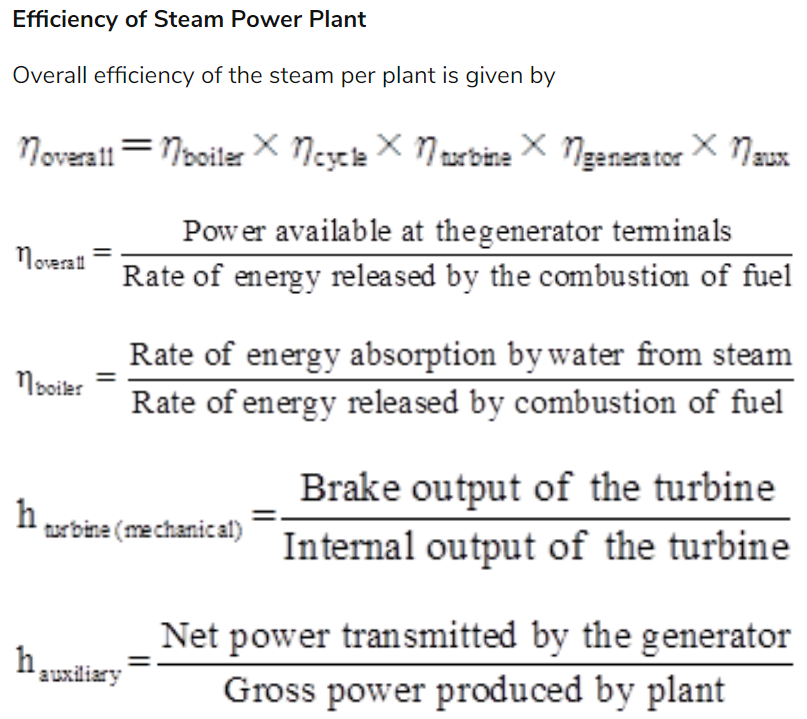
Efficiency

2. Overall Efficiency: The ratio of 'heat equivalent of electrical output' to the 'heat produced by combustion of coal ' is called as overall efficiency.

The overall efficiency of a thermal plant is about 29% (slightly less than the thermal efficiency).
The following list covers most of the factors that should be studied and considered in selection of proper sites for power plant construction:
1. Supply of Fuel
2. Geology and Soil Type
3. Availability of Water
4. Availability of Land
5. Transportation Facilities
6. Nearness to Load Centers
7. Distance from Populated Areas
Classification:
Blending:
Blending may be done with the following approach:
Beneficiation:
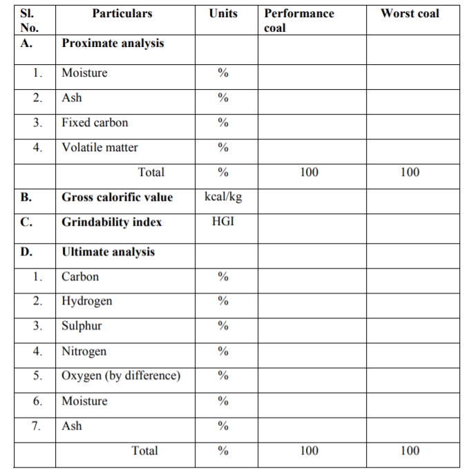
Coal preparation, or beneficiation, is a series of operations that remove mineral matter from coal.
Coal preparation processes are designed mainly to provide ash removal, energy enhancement, and product standardization . Sulphur reduction is achieved because the ash material removed contains pyritic sulphur.
Coal cleaning is used for moderate sulphur dioxide emissions control because physical coal cleaning is not effective in removing organically bound sulphur.
Chemical coal cleaning processes are being developed to remove the organic sulphur, but these are not used on a commercial scale.
The moisture content lowers the heating value, but it is usually minimal and has little impact on coal quality. It adds additional cost to the coal price; however, there are several benefits to reducing the ash content, including lower sulphur content, less ash to be disposed, lower transportation costs because more carbon and less ash is transported and increases in power plant peaking capacity, rated capacity and availability .
Developing circumstances are making coal cleaning more economical and a potential sulphur control technology, and include the following :
Selection is done under the following criteria:
1.12 Slurry type fuels
2 Coal water slurry
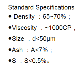
3 (CWS) is a novel coal-based fluid fuel, which is comprised of 65%-70% pulverized coal, 30%-
4 35% water and 1%-2% additive and physically processed. It can be easily loaded, stored and
5 pipeline transported just like gas. The paper discusses the proven application of CWS as a clean
6 fuel for power generation. It also presents it application, energy and cost efficiency prospects in
7 converting Heavy fuel oil with coal water slurry.
8 Coal water slurry
9 (CWS) is a novel coal-based fluid fuel, which is comprised of 65%-70% pulverized coal, 30%-
10 35% water and 1%-2% additive and physically processed. It can be easily loaded, stored and
11 pipeline transported just like gas. The paper discusses the proven application of CWS as a clean
12 fuel for power generation. It also presents it application, energy and cost efficiency prospects in
13 converting Heavy fuel oil with coal water slurry.
14 Coal water slurry
15 (CWS) is a novel coal-based fluid fuel, which is comprised of 65%-70% pulverized coal, 30%-
16 35% water and 1%-2% additive and physically processed. It can be easily loaded, stored and
17 pipeline transported just like gas. The paper discusses the proven application of CWS as a clean
18 fuel for power generation. It also presents it application, energy and cost efficiency prospects in
19 converting Heavy fuel oil with coal water slurry.
Coal Water slurry is a coal based fluid fuel which comprises of 65-70% of pulverized coal, 30-35% water and 1-2% additive and is physically processed.
It can be easily loaded, stored and transported easily just like a gas.
It is a clean fuel for power generation.
It produces energy and is cost efficient and is replacing heavy fuel oil.
Advantages:
It is universally accepted method of boiler firing in the modern age, mainly because it increases the thermal efficiency of solid fuel to a great extent. In this, the coal is made in fine particles with the help of grinding mills and the process is known as pulverization. This pulverized coal gets sprayed in the combustion chamber with a blow of hot air. The air used to spray the coal into the combustion chamber must get dry before entering the chamber. The extra air required for completion of the combustion is supplied separately, and this additional needed air is secondary air. The thermal efficiency of the pulverized fuel firing system depends on the fineness of the crushed coal. Pulverized fuel firing system is suitable when coal for combustion not ideal for solid fuel firing.
Advantages
Disadvantages
The velocity of air, causing fluidization depends on a number of parameter, like :-
Types of Fluidized Bed Combustion (FBC)
These are generally used in smaller plant, and has the capacity to produce steam of up to 6 tonnes per hour only. Their vertical shape reduces the overall dimension of the steam boiler, and is extremely efficient in plants, where space provision is limited.
2. Horizontal type FBC:
There are almost 10 times in capacity when compared to vertical type fluidized bed combustion. They can produce as much as 60 tonnes of steam per hour, and are placed horizontally with respect to the boiler tubes. The high capacity of the horizontal type Fluidized boilers coupled with their high efficiency, makes them an extremely desirable choice for the coal fired thermal power generating station.
Advantages
Features:
Advantages:
It is used to cool down the ash to a manageable temperature, transferred to a disposal area or stored for further use.
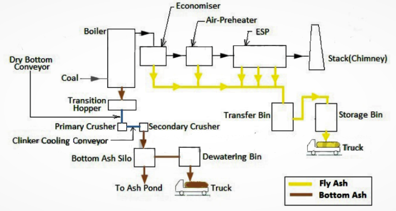
When the Coal combustion takes place in the boiler, some part of the coal remains unburnt and that un-burnt particles are called the Ash, which is approximately 26% to 40% of the total coal undergoing combustion. Basically this is nothing but the residual part of the coal. This ash will be extracted out in the form of Bottom Ash & Fly Ash according to the places of collection after the combustion.
If we calculate the ash percentage in any plant, then it will be as following:
Below mentioned values are the ash consumption in a 135 MW Sub-critical Boiler in terms of Metric Tons (MT). The coal consumption in a 135 MW Sub-critical boiler is around 2000 MT (Approx.) and compared to that the ash generation will be as follows.
For a 135 MW Bottom Ash Disposal (in 24 Hours) | 134 MT (Approx.) |
For a 135 MW Fly Ash Disposal (in 24 Hours) | 537 MT (Approx.) |
Ash Handling System mainly consists of the transportation of Fly ash and Bottom ash from boiler to the respective storing points and the system adopts transporting methods such as
Fly Ash Handling System
In Fly Ash Handling System, the major objective is to collect and transport the fly ash from the ash hoppers of the ESP to the Fly ash silo or to the Ash Slurry making tank. Generally the power plants prefer Dry Fly ash Disposal instead of making Ash Slurry from the Fly ash and the reason is that the fly ash collected from the ESP Bottom Hopper is very fine and suitable for Cement making, if we are making slurry of it then it will not be suitable for Cement making and economically also it is very good if you are selling the Ash to the Cement Plants. So these are the reasons why most of the plants are going for Fly ash Disposal instead of Slurry Disposal (Ash Water).
Slurry Type Fly Ash Disposal System: This is one of the simplest system for ash disposal from ESP hopper to the slurry pond.High Pressure water and fly ash is mixed below the ESP hopper and below in the diagram you can see that tapping for mixing of water is provided.
Dry Type Fly Ash Disposal System: Fly Ash from the ESP Hoppers is collected in the Ash Vessels and from there it is transported to the Fly Ash Silos by the help of Compressed air and from the Ash Silos, the ash is transported to the Bulkers(Sealed Vessel Trucks).
ESP Hopper: Hopper is a large conical type container used for dust or ash collection. After the field charging in ESP we go for hammering of collecting plates and the fly ash deposited on the collecting plates gets stored in the hopper. To ensure free flow of ash into the ash vessels from the hopper, the lower portions of the hoppers are provided with electric heaters. Because if the temperature of the ash falls below the ash fusion temperature then the ash will form big clusters and may choke the entire conveying system.
Dome valve: It is situated between the ESP hopper and Ash vessel; it is a special type of valve which is highly leak proof. It consists of a dome type structure with a rubber seal which is continuously getting supply from the compressed air.
Air Vent Line: To remove the trapped air from the vessel, we use vent line and due to this line air from the vessel is transported to Hopper and ash come down. It basically does two things, first of all by removing the air from the vessel, it is removing the back-pressure from the Vessel and simultaneously it is pressurizing the ash hopper.
Compressor: A compressed air station is set up in the plant. The compressed air station provides air for the pneumatic conveying system and purging of fabric filters as we already explained in ESP. After compressing the air, we have to remove all the moisture content from the air. To remove the moisture from air we use Adsorbent Air Drier (AAD) and Refrigeration Air Drier (RAD).The pressure of the compressor is depended on the system design.
Ash Vessels: Ash vessels are present just below the ESP hoppers with the Dome Valve assembly. They are supposed to contain the fly ash for a certain amount of time which will be carried to the fly ash silos. Their ash holding capacity is depended on the conveying capacity of the ash line to the Ash Silos.
Wet Fly Ash Disposal System: Up to the hopper part it is same as that of Dry Fly Ash handling system. After the hopper instead of going into the vessel, the ash gets mixed with a high Pressure water and this mixture goes to a slurry tank for further pumping. The slurry formed is further pumped through a series of pumps or a single GEVO pump for dumping in the Ash yard. For mixing of fly ash with water, a tapping is provided for High Pressure water below the hopper.
Bottom ash handling System
The bottom ash quantity is around 20% of the total Ash generation and there are mainly two types of bottom ash disposal systems.
Dry Type Bottom Ash Disposal: First of all we will discuss about the Dry type bottom ash disposal system.
Submerged Scrapper Conveyor: Submerged Scraper Conveyor is used for cooling and transmitting the hot bottom ash. The scraper conveyor used to send the bottom ash to the bottom ash silo. The Bottom ash hoppers are partially filled with water in order to avoid the direct impact of the Clinkers due to free fall. Whatever the ash, falling on the SSC conveyor is getting scrapped by the scrappers to the clinker grinder.
Clinker Grinder: A clinker grinder is provided at the outlet of SCC to control the bottom ash size as in the bottom ash there will be some big clinkers and to make the ash of even size we use a clinker grinder.The output of the bottom ash after the clinker grinder is around 25mm to 50mm,it is adjustable.
Drag Conveyor: It transmits the crusher output to the bottom ash silo. It is same as that of scrapper conveyor. Just for conveying purpose for the bottom ash.
Bottom ash silo: Each boiler is equipped with a bottom ash silo. It is used for storing the bottom ash for a period of time and then it is dumped in the trucks for disposal.
Slurry Type Bottom Ash Disposal: Here the bottom ash from the 2nd pass of the Boilers goes to the Clinker Grinder in the 1st pass by the help of high pressure water and from the Clinker Grinder all the ash goes to a slurry sump for further pumping.
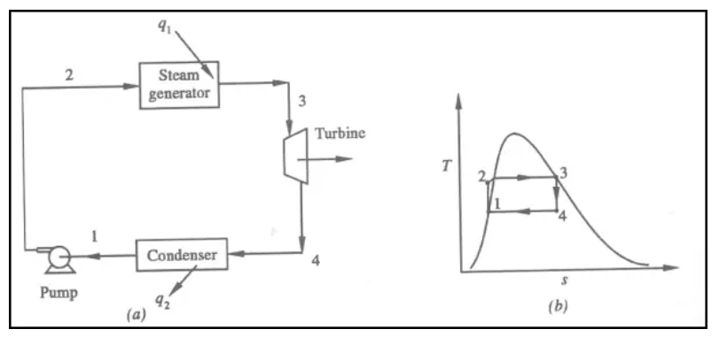
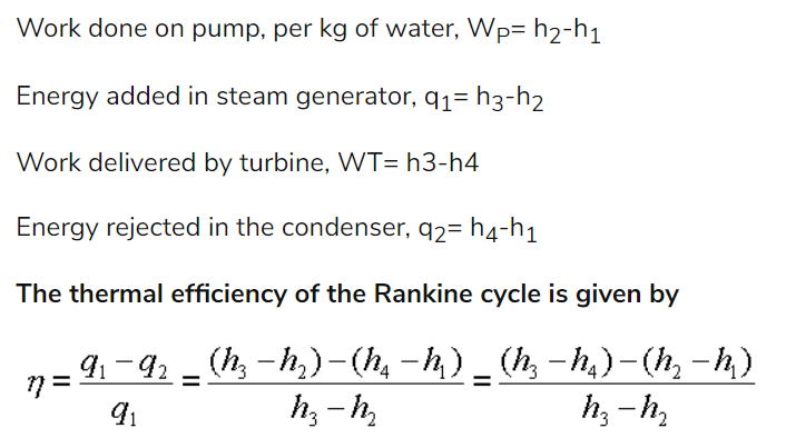
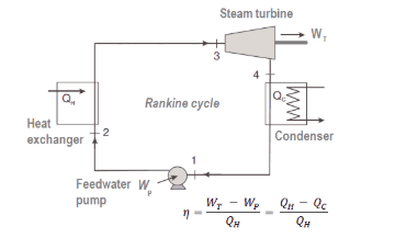
RANKINE CYCLE
It is a fundamental operating cycle of all power plants where an operating fluid is continuously evaporated and condensed.
Here,
1-2 shows Isentropic compression
2-3 Isobaric Heat Transfer
3-4 Isentropic Expansion
4-1 Isobaric Heat Rejection
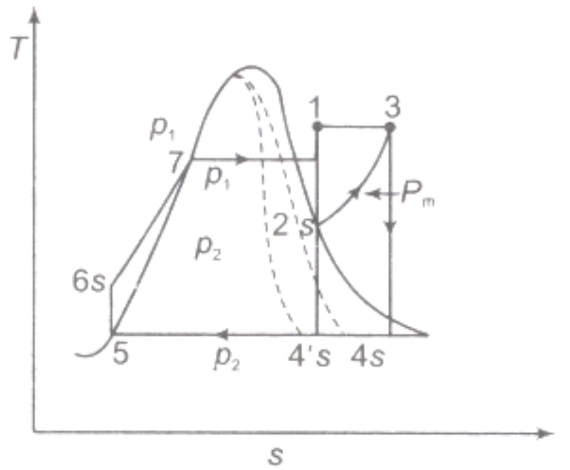
REHEATING OF STEAM
In the reheat cycle, the expansion of steam from initial state 1 to the condenser pressure is carried out in two or more steps depending upon the number of reheats used. It increases the net work output of the turbine.
Advantages:
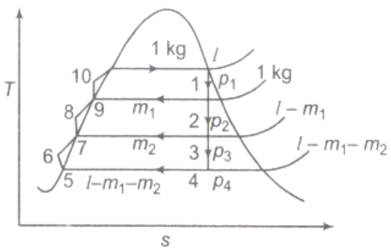
REGENERATION
The mean temperature of heat addition can also be increased by reducing the amount of heat added at low temperatures in the economizer section of steam generator. Here, the energy is exchanged internally between the expanding fluid in the turbine and compressed fluid before heat addition.

Numerical:
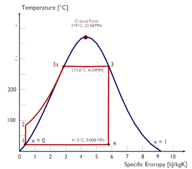
Assume a simple cycle without reheat and without with condensing steam turbine running on saturated steam (dry steam). In this case the turbine operates at steady state with inlet conditions of 6 MPa, t = 275.6°C, x = 1 (point 3). Steam leaves this stage of turbine at a pressure of 0.008 MPa, 41.5°C and x = ??? (point 4).
Calculate:

Solution:
1)Since we do not know the exact vapor quality of the outlet steam, we have to determine this parameter. State 4 is fixed by the pressure p4 = 0.008 MPa and the fact that the specific entropy is constant for the isentropic expansion (s3 = s4 = 5.89 kJ/kgK for 6 MPa). The specific entropy of saturated liquid water (x=0) and dry steam (x=1) can be picked from steam tables. In case of wet steam, the actual entropy can be calculated with the vapor quality, x, and the specific entropies of saturated liquid water and dry steam:
s4 = sv x + (1 – x ) sl
where
s4 = entropy of wet steam (J/kg K) = 5.89 kJ/kgK
sv = entropy of “dry” steam (J/kg K) = 8.227 kJ/kgK (for 0.008 MPa)
sl = entropy of saturated liquid water (J/kg K) = 0.592 kJ/kgK (for 0.008 MPa)
From this equation the vapor quality is:
x4 = (s4 – sl) / (sv – sl) = (5.89 – 0.592) / (8.227 – 0.592) = 0.694 = 69.4%
2)The enthalpy for the state 3 can be picked directly from steam tables, whereas the enthalpy for the state 4 must be calculated using vapor quality:
h3, v = 2785 kJ/kg
h4, wet = h4,v x + (1 – x ) h4,l = 2576 . 0.694 + (1 – 0.694) . 174 = 1787 + 53.2 = 1840 kJ/kg
Then the work done by the steam, WT, is
WT = Δh = 945 kJ/kg
3)Enthalpy for state 1 can be picked directly from steam tables:
h1, l = 174 kJ/kg
State 2 is fixed by the pressure p2 = 6.0 MPa and the fact that the specific entropy is constant for the isentropic compression (s1 = s2 = 0.592 kJ/kgK for 0.008 MPa). For this entropy s2 = 0.592 kJ/kgK and p2 = 6.0 MPa we find h2, subcooled in steam tables for compressed water (using interpolation between two states).
h2, subcooled = 179.7 kJ/kg
Then the work done by the pumps, WP, is
WP = Δh = 5.7 kJ/kg
4)The enthalpy difference between (2 → 3), which corresponds to the net heat added in the steam generator, is simply:
Qadd = h3, v – h2, subcooled = 2785 – 179.7 = 2605.3 kJ/kg
5)This heat engine would have a Carnot efficiency of
ηCarnot = 1 – Tcold/Thot = 1 – 315/549 = 42.6%
where the temperature of the hot reservoir is 275.6°C (548.7 K), the temperature of the cold reservoir is 41.5°C (314.7K).
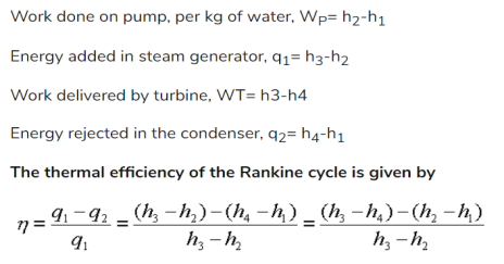
The thermodynamic efficiency of this cycle can be calculated by the following formula:

thus
ηth = (945 – 5.7) / 2605.3 = 0.361 = 36.1%
A steam power plant must have following equipment :
(a) A furnace to burn the fuel.
(b) Steam generator or boiler containing water. Heat generated in the furnace is utilized to convert water into steam.
(c) Main power unit such as an engine or turbine to use the heat energy of steam and perform work.
(d) Piping system to convey steam and water.
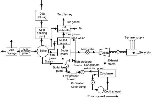
The flow sheet of a thermal power plant consists of the following four main circuits : (a) Feed water and steam flow circuit.
(b) Coal and ash circuit.
(c) Air and gas circuit.
(d) Cooling water circuit.
A steam power plant using steam as working substance works basically on Rankine cycle. Steam is generated in a boiler, expanded in the prime mover and condensed in the condenser and fed into the boiler again.
The different types of systems and components used in steam power plant are as follows :
(a) High pressure boiler
(b) Prime mover
(c) Condensers and cooling towers
(d) Coal handling system
(e) Ash and dust handling system
(f) Draught system
(g) Feed water purification plant
(h) Pumping system
(i) Air preheater, economizer, super heater, feed heaters.
Air taken from the atmosphere is first passed through the air pre-heater, where it is heated by flue gases. The hot air then passes through the furnace. The flue gases after passing over boiler and superheater tubes, flow through the dust collector and then through economiser, air pre-heater and finally they are exhausted to the atmosphere through the chimney.
Steam condensing system consists of the following :
(a) Condenser
(b) Cooling water
(c) Cooling tower
(d) Hot well
(e) Condenser cooling water pump
(f) Condensate air extraction pump
(g) Air extraction pump
(h) Boiler feed pump
(i) Make up water pump.
Numerical:
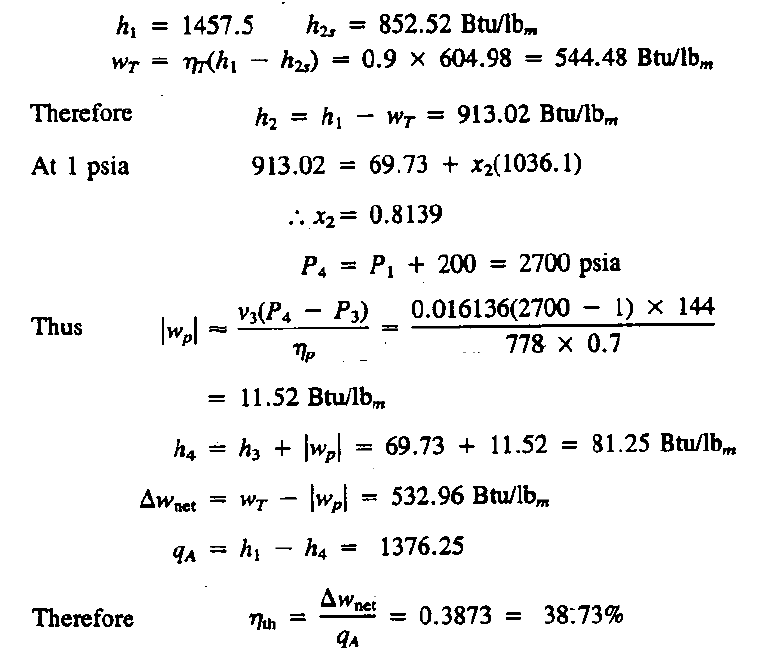
Solution:

Solution:

References :
1. E.I.Wakil, Power Plant Engineering‖, McGraw Hill Publications New Delhi
2. P.K.Nag, Power Plant Engineering‖, McGraw Hill Publications New Delhi.
3. R.Yadav , Steam and Gas Turbines‖ ,Central Publishing House, Allahabad.
4. G.D.Rai, Non-Conventional Energy Sources, Khanna Publishers,Delhi
5. S.P.Sukhatme, Solar Energy‖ Tata McGraw-Hill Publications, New Delhi
6. G R Nagpal Power Plant Engineering , Khanna Publication

