Unit 2
Steam Condenser and Environmental Impacts of Thermal Power Plant
Objectives
2. It supplies pure feed water to the hot well and from hot well the water is again pumped to the boiler with the help of boiler feed pump.
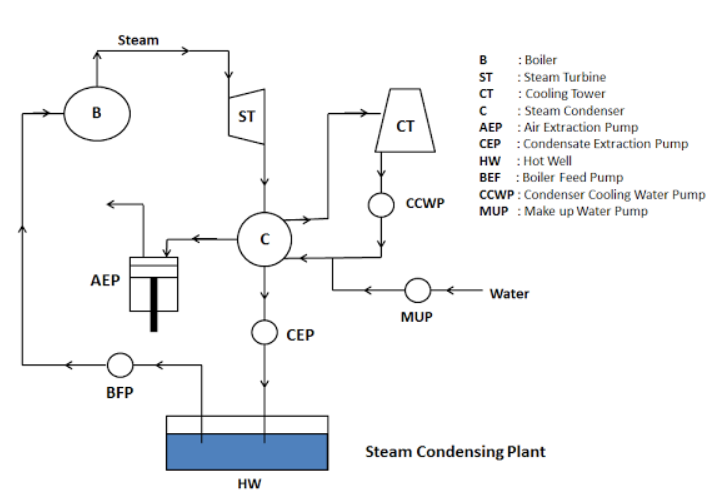
1. Condenser: It is a closed vessel used to condense the steam. The low pressure steam gives off its heat to the coolant (here water from cooling tower) and gets converted into water during the process of condensation.
2. Condensate Extraction Pump: It is a pump which is installed in between the condenser and hot well. It transfers the condensate from the condenser to the hot well.
3. Hot Well: It is a sump that lies in between the condenser and boiler. It receives the condensate from the condenser by condensate pump. The feed water is transferred from the hot well to the boiler.
4. Boiler Feed Pump: It is a pump installed in between the hot well and boiler. It pumps the feed water from the hot well to the boiler. And this is done by increasing the pressure of condensate above boiler pressure.
5. Air Extraction Pump: It is a pump used to extracts or removes the air from the steam condenser.
6. Cooling Tower: It is a tower which contains the cold water and this water is made to circulate within the condenser for cooling of steam.
7. Cooling Water Pump: It is a pump lies in between the cooling tower and condenser. It circulates the cooling water through the condenser.
The steam condenser is classified as
2. Surface condenser or non-mixing type condenser
Jet Condenser
Jet condenser is a condenser in which the condensate gets mixed with the cooling water. That’s why it is also called as mixing type condenser.
This type of condenser is used sometime because it lost some of the condensate and requires high power for the pump during the process of condensation.
In jet condenser, as the condensate is not free from the salt, so it cannot be used as feed water for the boiler. It can be used at the place where sufficient amount of good quality water is available.
Types of Jet Condenser
(i) Parallel Flow Jet Condenser
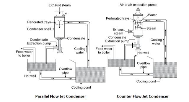
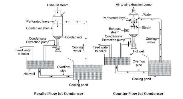
In parallel flow jet condenser, the steam and water enters into the condenser at the top and leaves at the bottom.
The cooling water and steam enters at the top. As both steam and cooling water mix with each other, the steam gets condense. The condensate, cooling water and air moves downward and it is removed by two separate pumps known as air extraction pump and condensate extraction pump. The condensate pump transfers the condensate to the hot well and from there the extra water is made to flow in cooling water tank or pond through overflow pipe.
(ii) Counter Flow or Low Level Jet Condenser
In counter Flow or low level jet condensers, the steam enters at the bottom and the cooling water at the top. The steam flows upward and meets the cooling water coming downward.
In these types of steam Condensers, the air pump is located at the top. Air pump creates vacuum and this vacuum draws water from the cooling tower. The cooling water enter into the condenser and falls on the perforated conical plate. The perforated conical plates convert the cooling water into a large number of jets as shown in the figure. The falling jet of water caught in the trays and from there it escapes out in second series of jets and meets the exhaust steam entering at the bottom. As the steam mix with the water, it gets condense. The condensate and cooling water moves down through a vertical pipe to the condensate pump. And finally the pump delivers it to the hot well.
(iii) Barometric or High Level Jet Condenser
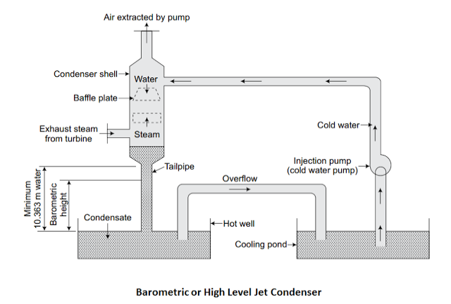
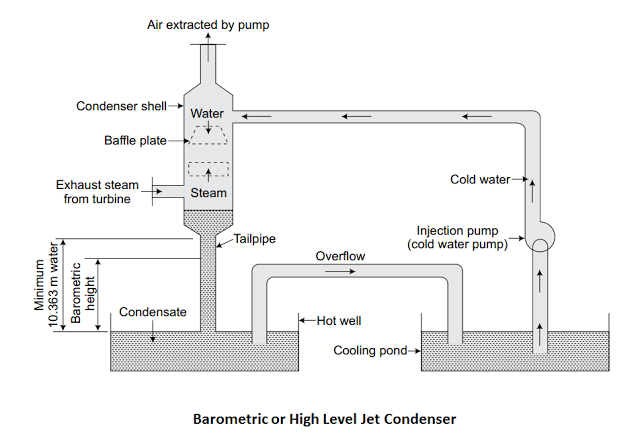
Barometric or high level jet condensers are provided at high level with a long vertical discharge tube or tailpipe. It does not have condensate extraction pump and the condensate and cooling water flows in the hot well because of the gravity. An injector pump is used to flow cooling water at the top of the condenser.
These types of jet condensers are used at a high level with a vertical discharge pipe. In this condenser, the steam enters at the bottom and flows in upward direction and meets with the down coming cooling water. Its working is similar as the low level jet condenser. The vacuum is created at the top of the condenser shell. With the help of vacuum and injector pump, the cooling water is moved to the top of the condenser. The condensate and cooling water comes down in the hot well through a long vertical discharge pipe. And finally the extra hot water flows to the cooling tank or cooling pond by an overflow pipe
(iv) Ejector Condenser
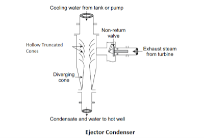
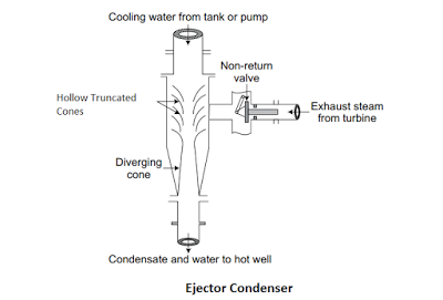
In ejector condensers, it has a non-return valve through which exhaust steam enters, hollow truncated cones, and diverging cone.
In these condensers, the cooling water is injected at the top. The steam enters into the condenser through a non-return valve. The steam and water mixes with each other while passing through series of hollow truncated metal cones and steam changes into water. At the end of the metal cones a diverging cone is present. When the condensate passes through diverging cone, its kinetic energy is partly transformed into pressure energy.
The condensate and cooling water is then discharged to the hot well.
Surface Condensers
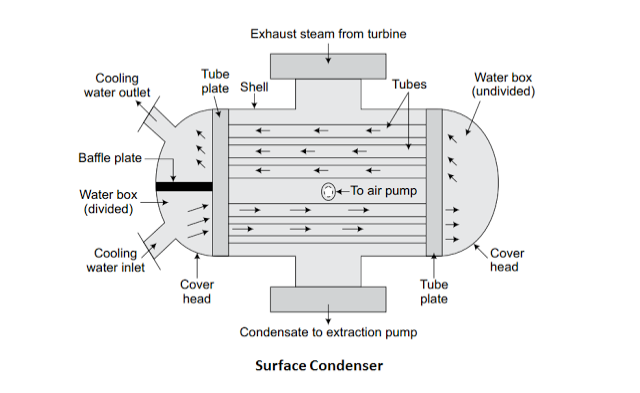
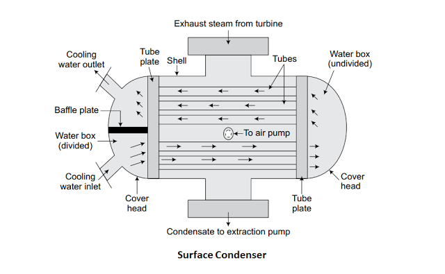
Surface condenser is a type of steam condenser in which the steam and cooling water do not mix with each other. And because of this, the whole condensate can be used as boiler feed water. It is also called as non-mixing types condenser.
The figure above shows the longitudinal section of a two pass surface condenser. It consists of a horizontal cylindrical vessel made of cast iron and packed with tubes. The cooling water flows through these tubes. The ends of the condensers are cut off by the perforated type plates. The tubes are fixed into these perforated type plates. It is fixed in such a manner that any leakage of water into the center of condensing space is prevented. The water tubes are passed horizontally through the main condensing space. The exhaust steam from the turbine or engine enters at the top and forced to move downward due to the suction of the air extraction pump. In this steam condenser, the cooling water enters into boiler through lower half of the tubes in one direction and returns in opposite direction through the upper half as shown in the figure above.
This type of condenser is used in ships as it can carry only a limited quantity of water for the boiler. It is also widely used for the land installation where there is a scarcity of good quality of water.
Types of Surface Condensers
The surface condenser on the basis of direction of flow of condensate, the arrangement of the tubing system and the position of the extraction pump are classified as
(i) Down Flow
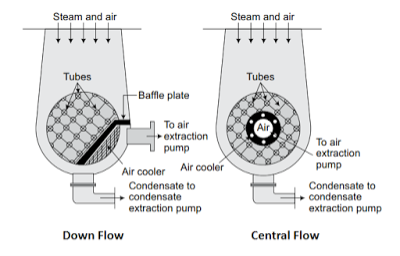
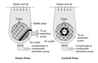
In Down flow surface condenser, the steam enters at the top of the condenser and flows downwards over the tubes due to the gravity and air extraction pumps. The condensate gets collected at the bottom and then pumped with the help of condensate extraction pump. The pipe of dry air extraction pump is provided near the bottom and it is covered by baffle plates so as to prevent the entry of the condensate into it.
The steam in down flow condenser flows perpendicular to the direction of flow of cooling water, so it is also called as cross-surface condenser.
(ii) Central Flow
In central flow condenser, the steam enters at the top of the condenser and flows in downward direction. In this the suction pipe of the air extraction pump is provided in the center of the tube nest as shown in the figure. Due to this placement of the suction pipe in the center of the tube nest, the exhaust steam flows radially inward over the tubes towards the suction pipe. The condensate is collected at the bottom of the condenser and pumped to the hot well.
(iii) Regenerative
In regenerative surface condensers, the condensate is heated by the use of regenerative method. In that the condensate is passed through the exhaust steam coming out from the turbine or engine. This raises its temperature and it is used as the feed water for the boiler.
(iv) Evaporative
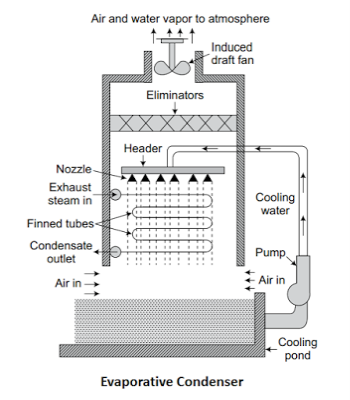
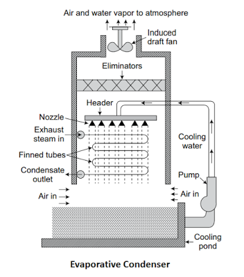
In evaporative surface condensers, the steam enters at the top of the condenser in a series of pipes over which a film of cold water is falling. At the same time, current of air is made to circulate over the film of water. As the air circulates over the water film, it evaporates some of the cooling water. As a result of this rapid evaporation, the steam circulating inside the series of pipes gets condensed. Remaining cooling water that left is collected at an increased temperature and reused. It is brought to the original temperature by adding required quantity of cold water.
Advantages of Steam Condenser
Comparison of Jet and Surface Condenser
S.no | Jet Condenser | Surface Condenser |
1. | Exhaust steam and cooling water mixed with each other. | Exhaust steam and cooling water are not mixed with each other. |
2. | It is less suitable for high capacity plants. | It is more suitable for high capacity plants. |
3. | The condensing plant using this type of steam condenser is simple and | The condensing plant using surface condenser is costly and |
4. | Condensate is wasted and cannot be reused. | The condensate is reused. |
5. | Less quantity of circulating water is required. | Large quantity of circulating water is required. |
6. | It has low maintenance cost. | It has high maintenance cost. |
7. | In jet condenser, more power is required for the air pump. | In surface condenser, less power is required for the air pump. |
8. | High power is required for water pumping. | Less power is required for water pumping. |
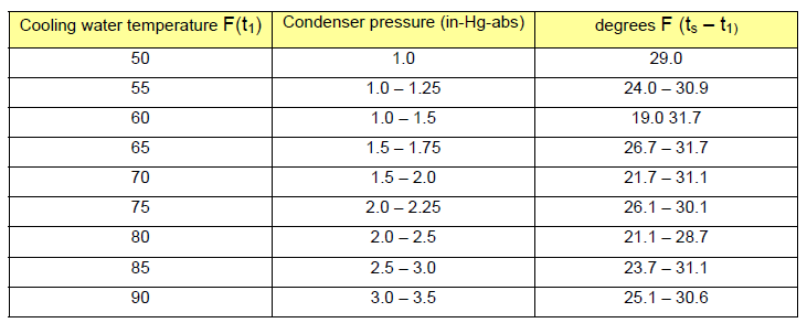
1. INLET TEMPERATURE
2. TERMINAL DIFFERENCE
It is the difference in temperature between the steam saturation temperature (ts) with respect to condenser pressure and outlet cooling temperature (t2).
3. TEMPERATURE RISE
It is the difference between inlet and outlet cooling water temperatures. It ranges between 100F to 250F.
2.5 Condenser efficiency
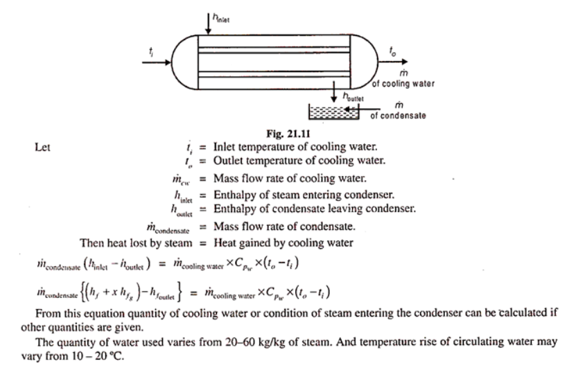
The condenser efficiency may be defined as ''the ratio of the difference between the outlet and inlet temperature of cooling water to the difference between the temperature corresponding to the vacuum in the condenser and the inlet temperature of the cooling water."
Then, it is given by,
It may be defined as the ratio of actual vacuum as recorded by the vacuum gauge to the ideal vacuum.
It is given by,
Numericals:
Barometer reading – 766 mm of mercury
Actual vaccum in condenser - 710 mm of mercury
Temp of hot well – 290C
Inlet temp of cooling water - 180C
Outlet temp of cooling water - 270C
Determine:
A) Vaccum corrected to a saturated barometer of 760 mm of mercury
B) Vaccum efficiency
C) Under cooling of condensate
D) Coefficient of performance
Solution:
Absolute vaccum = 766 – 710 = 56 mm of mercury
Corrected vaccum = 760-56 = 704 mm of mercury
Vaccum efficiency = (Actual vaccum)/ Ideal vaccum
= (766 – 56)/ (766- 30.43)
= 710/735.57
= 0.9652 = 96.52%
Under cooling of condensate = 39-29 =100C
Coefficient of performance = (t2 – t1)/(ts – t1)
= (27-18)/(29-18)
= 0.8181 = 81.81%
Application:
Function:
It cools the cooling water of the condenser, by the current of air flowing in the opposite direction.
A large amount of cooling water is required for condensation in large capacity power plants. If the water is freely available either from the river or lake, then the water can be directly pumped from the river to the condenser as shown in Fig.
If the water is not freely available, then a cooling tower has to be used for cooling the hot water of condenser. The cooled water can be used again as cooling water for the condenser.
Figure below shows the hyperbolic cooling tower. It is usually made of steel Reinforced cement concrete. The hot water from the condenser is supplied to the ring troughs which are placed at 8-10 m above the ground level. The nozzles are provided on the bottom side of troughs to break up water into sprays.
The air rises up from the pond in the opposite direction of water flow and absorbs heat from the falling water spray. The cooled water is collected into a pond built below the tower. This type of cooling tower is generally used since it is very efficient, however, it needs about 3-5 % of makeup water for compensating the evaporation losses.
Types:
(i) Natural Draught Towers:
In this type the circulation of air is obtained by virtue of pressure difference of the air inside and outside the tower. Here no fan is required.
(ii) Forced Draught Tower:
In this case, the circulation of air is obtained by means of fans provided at the bottom of the tower.
(iii) Induced Draught Tower:
In this case, the circulation of air is obtained by providing a fan at the top of the tower.
Air pump is a machine which is used in the condenser to remove condensate air from the condenser. Basically, Air pump creates a vacuum in the condenser as nearly as possible, corresponding to exhaust steam temperature. It is used in the condenser to remove both air and condensate from the condenser.
There are two types of air pump available in the market.
The pump which extracts both condensate and air is called wet air pump and a pump which extracts only moist air is known as dry air pump. Rotary type air pump is also present in the market but it is not so popular.
2.10 Environmental impact of thermal power plants
Impact on Air, Water, Soil and People:
Health Impacts
Chemical Pollutant | Health Impact |
Sulphur Dioxide |
|
Nitrous Oxides |
|
Particulate Matter(PM): |
|
Ammonia |
|
Hydrogen Chloride and Fluoride |
|
Dioxins and Furan |
|
Polycyclic Aromatic Hydrocarbons |
|
Mercury |
|
Lead |
|
Antimony, Arsenic, Beryllium, Cadmium, Nickel, Selenium, Manganese |
|
Radium |
|
Uranium |
|
Air pollution control – Point source
2.14 Dust handling systems
Fugitive Dust Control

Sources of water pollution:
The term thermal pollution has been used to indicate the detrimental effects of heated effluent discharge by various power plants. It denotes the impairment of quality and deterioration of aquatic and terrestrial environment by various industrial plants like thermal, atomic, nuclear, coal-fired plants, oil field generators, factories, and mills.
Sources:
1. Nuclear Power Plant
2. Coal-fired power Plant
3. Industrial Effluents
4. Domestic Sewage
5. Hydro-electric power
6. Thermal Power Plant
Effects:
The harmful effects of the thermal pollution are discussed below:
1. Reduction in dissolved Oxygen
The pollutant from various industrial plants are heated decreases the concentration of oxygen with an increase in the temperature of water.
2. Change in water properties
The decrease in density, viscosity and solubility of gases in water increases the setting speed of suspended particles which seriously affect the food supplies of aquatic organism.
3. Increase in toxicity
The concentrated pollutant causes the rise in the temperature of water which increases the toxicity of the poison present in water. The toxicity in water will increase the death rate in marine life.
4. Disruption of Biological activities
Temperature changes disrupt the entire marine ecosystem because changes in temperature causes change in physiology, metabolism and biological process like respiration rate, digestion, excretion and development of an aquatic organism.
The unwanted sound that can have deleterious effects on human health and environmental quality is known as Noise Pollution.
It is generated inside many industrial facilities and some other workplaces, but it also comes from highway, railway, and airplane traffic and from outdoor construction activities.
Frequency of a sound wave is expressed in cycles per second (cps), but hertz (Hz) is more commonly used (1 cps = 1 Hz). The human eardrum is a very sensitive organ with a large dynamic range, being able to detect sounds at frequencies as low as 20 Hz (a very low pitch) up to about 20,000 Hz (a very high pitch). The pitch of a human voice in normal conversation occurs at frequencies between 250 Hz and 2,000 Hz.
High Noisy Area Section of TPP
Control:
Design of equipments, Acoustic enclosures / barrier shields ,Construction of sound barrier in the form structure , Personal protective equipment i.e. ear plug & ear muffs ,More than 33 % of total area under green cover
References:
1. E.I.Wakil, Power Plant Engineering‖, McGraw Hill Publications New Delhi
2. P.K.Nag, Power Plant Engineering‖, McGraw Hill Publications New Delhi.
3. R.Yadav , Steam and Gas Turbines‖ ,Central Publishing House, Allahabad.
4. G.D.Rai, Non-Conventional Energy Sources, Khanna Publishers,Delhi
5. S.P.Sukhatme, Solar Energy‖ Tata McGraw-Hill Publications, New Delhi
6. G R Nagpal Power Plant Engineering , Khanna Publication
