Unit 4
Diesel and Gas Turbine Power plant
1. We can use it with thermal or hydro power plant as a peak load plant in combination.
2. For mobile power generation and transportation systems.
3. It is economical for industries that require lower power generation.
4. I is used for electric power generation too.
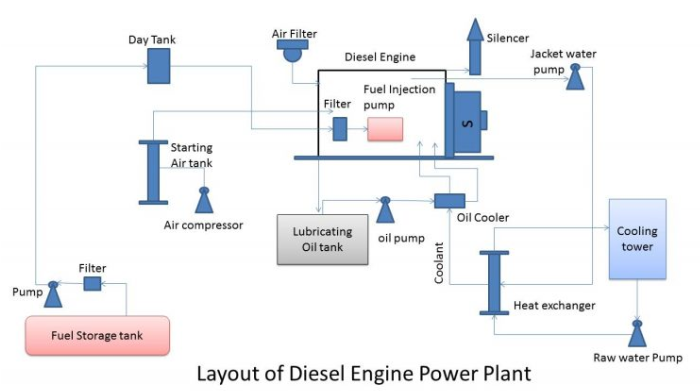
Fuel Supply System
In fuel supply system there are one storage tank strainers, fuel transfer pump and all day fuel tank. Storage tank where oil in stored.
Strainer : This oil then pump to dry tank, by means of transfer pump.
During transferring from main tank to smaller dry tank, the oil passes through strainer to remove solid impurities. From dry tank to main tank, there is another pipe connection. This is over flow pipe. This pipe connection is used to return the oil from dry tank to main tank in the event of over flowing.
From dry tank the oil is injected in the diesel engine by means of fuel injection pump.
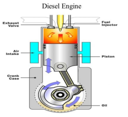
Air Intake System
This system supplies necessary air to the engine for fuel combustion. It consists of a pipe for supplying of fresh air to the engine. Filters are provided to remove dust particles from air because these particles can act as an abrasive in the engine cylinder.
Exhaust System
The exhaust gas is removed from engine, to the atmosphere by means of an exhaust system. A silencer is normally used in this system to reduce noise level of the engine.
Cooling System
The heat produced due to internal combustion, drives the engine. But some parts of this heat raise the temperature of different parts of the engine. High temperature may cause permanent damage to the machine. Hence, it is essential to maintain the overall temperature of the engine to a tolerable level. Cooling system of diesel power station does exactly so. The cooling system requires a water source, water source, water pump and cooling towers. The pump circulates water through cylinder and head jacket. The water takes away heat from the engine and it becomes hot. The hot water is cooled by cooling towers and is re-circulated for cooling.
Lubricating System
This system minimises the wear of rubbing surface of the engine. Here lubricating oil is stored in main lubricating oil tank. This lubricating oil is drawn from the tank by means of oil pump. Then the oil is passed through the oil filter for removing impurities. From the filtering point, this clean lubricating oil is delivered to the different points of the machine where lubrication is required the oil cooler is provided in the system to keep the temperature of the lubricating oil as low as possible.
Engine Starting System
For starting a diesel engine, initial rotation of the engine shaft is required. Until the firing start and the unit runs with its own power. For small DG set, the initial rotation of the shaft is provided by handles but for large diesel power station. Compressed air is used for starting.
Fuel Supply System
In fuel supply system there are one storage tank strainers, fuel transfer pump and all day fuel tank. Storage tank where oil in stored.
Strainer : This oil then pump to dry tank, by means of transfer pump.
During transferring from main tank to smaller dry tank, the oil passes through strainer to remove solid impurities. From dry tank to main tank, there is another pipe connection. This is over flow pipe. This pipe connection is used to return the oil from dry tank to main tank in the event of over flowing.
From dry tank the oil is injected in the diesel engine by means of fuel injection pump.
Air Intake System
This system supplies necessary air to the engine for fuel combustion. It consists of a pipe for supplying of fresh air to the engine. Filters are provided to remove dust particles from air because these particles can act as an abrasive in the engine cylinder.
Exhaust System
The exhaust gas is removed from engine, to the atmosphere by means of an exhaust system. A silencer is normally used in this system to reduce noise level of the engine.
Cooling System
The heat produced due to internal combustion, drives the engine. But some parts of this heat raise the temperature of different parts of the engine. High temperature may cause permanent damage to the machine. Hence, it is essential to maintain the overall temperature of the engine to a tolerable level. Cooling system of diesel power station does exactly so. The cooling system requires a water source, water source, water pump and cooling towers. The pump circulates water through cylinder and head jacket. The water takes away heat from the engine and it becomes hot. The hot water is cooled by cooling towers and is re-circulated for cooling.
Lubricating System
This system minimises the wear of rubbing surface of the engine. Here lubricating oil is stored in main lubricating oil tank. This lubricating oil is drawn from the tank by means of oil pump. Then the oil is passed through the oil filter for removing impurities. From the filtering point, this clean lubricating oil is delivered to the different points of the machine where lubrication is required the oil cooler is provided in the system to keep the temperature of the lubricating oil as low as possible.
Engine Starting System
For starting a diesel engine, initial rotation of the engine shaft is required. Until the firing start and the unit runs with its own power. For small DG set, the initial rotation of the shaft is provided by handles but for large diesel power station. Compressed air is used for starting.
4.6 Performance of DPP (Numerical Treatment) advantages & disadvantages of diesel power plant
The performance of the diesel engine focuses on the power and efficiency. The engine varies with parameters of the engine like piston speed, air-fuel ratio, compression ratio inlet air-pressure and temperature.
The two usual conditions under which I.C. engines are operated are :
(a) constant speed with variable load, and
(b) variable speed with variable load.
The first situation is found in a.c. generator drives and the second one in automobiles, railway engines and tractors etc. A series of tests are carried out on the engine to determine its performance characteristics, such as : indicated power (I.P.), Brake power (B.P.), Frictional Power (F.P.), Mechanical efficiency (ηm), thermal efficiency, fuel consumption and also specific fuel consumption etc. The measurement of these quantities is discussed below.
Indicated Mean Effective Pressure (IMRP) In order to determine the power developed by the engine, the indicator diagram of engine should be available. From the area of indicator diagram it is possible to find an average gas pressure which, while acting on piston throughout one stroke, would account for the network done. This pressure is called indicated mean effective pressure (IMEP). Indicated Horse Power (IHP).
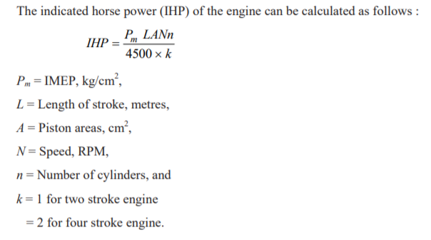
The indicated horse power (IHP) of the engine can be calculated as follows :
INDICATED HORSE POWER
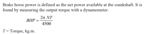
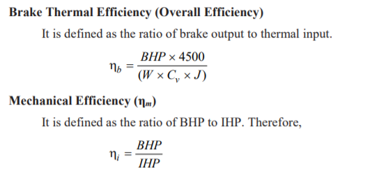
BRAKE HORSE POWER
FRICTIONAL HORSE POWER

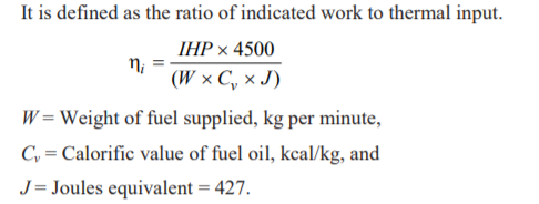
INDICATED THERMAL EFFICEENCY
Advantages of Diesel Power Station
Disadvantages of Diesel Power Station
4.8 Gas Turbine Power Plant
The primary arrangement of all power plants is to rotate the prime mover so that alternator can generate required electricity. In gas turbine power plant we use high pressure and temperature air instead of high pressure and temperature steam to rotate the turbine.
The fundamental working principle of a gas turbine power plant is same as that of a steam turbine power plant. The only difference is there that in steam turbine power plant we use compressed steam to rotate the turbine, but in gas turbine power plant we use compressed air to turn the turbine.
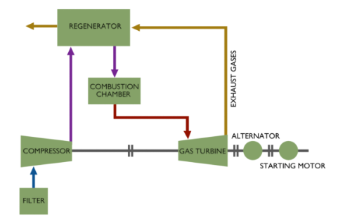
In the open cycle gas turbine, air is drawn into the compressor from atmosphere and is compressed. The compressed air is heated by directly burning the fuel in the air at constant pressure in the combustion chamber.
Then the high pressure hot gases expand in the turbine and mechanical power is developed. Part of the power developed by the turbine (about 66%) is used for driving the compressor. The remaining is available as useful output.
The working fluid, air and fuel, must be replaced continuously as they are exhausted into the atmosphere. Thus the entire flow comes from the atmosphere and is returned to the atmosphere.
In this, the compressed air from the compressor is heated in a heat exchanger (air heater) by some external source of heat (coal or oil) at constant pressure.
Then the high pressure hot gases expand passing through the turbine and mechanical power is developed.
The exhaust gas is then cooled to its original temperature in a cooler before passing into the compressor again.
The main difference between the open and closed cycles is that the working fluid is continuously replaced in open cycle whereas it is used again and again in a closed cycle.
The open cycle plant is much lighter than the closed cycle. Hence it is widely used.
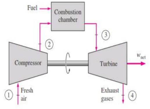
It has three major components: Compressor, combustor and power turbine.
At ambient conditions, air is drawn into the compressor where its temperature and pressure is raised.
The pressure air moves to the combustion chamber where the fuel is burnt at constant pressure.
This high temperature gases enters the turbine where they expand to atmospheric pressure which producing power output.
Some amount of output power is used to drive the compressor and the remaining is used for shaft work.
The exhaust gases leaving the turbine are thrown out causing the cycle to be classified as open cycle.
Advantages:
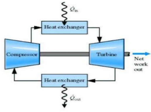
In this the working fluid does not come in contact with the atmospheric air.
The compression and expansion processes remain the same but combustion process is replaced by constant pressure heat addition process from an external source.
The exhaust process is replaced by constant pressure heat rejection process to the ambient air.
The cold gas is drawn into the compressor where its temperature and pressure are raised.
The high pressure air moves to the combustion chamber where fuel is burnt at constant pressure.
The high temperature gases then enter the turbine where they expand to atmospheric pressure while producing power output.
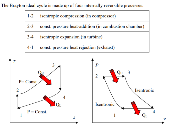
Brayton cycle is the ideal cycle for gas-turbine engines in which the working fluid undergoes a closed loop. That is the combustion and exhaust processes are modeled by constant-pressure heat addition and rejection, respectively.
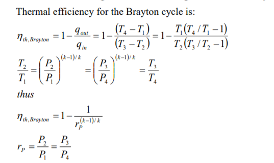
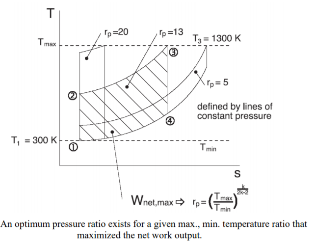
where rP is called the pressure ration and k = cp /cv is the specific heat ratio.
Given that the maximum and minimum temperature can be prescribed for the Brayton cycle, a change in the pressure ratio can result in a change in the work output from the cycle.
Given that the maximum and minimum temperature can be prescribed for the Brayton cycle, a change in the pressure ratio can result in a change in the work output from the cycle.
The maximum temperature in the cycle T3 is limited by metallurgical conditions because the turbine blades cannot sustain temperatures above 1300 K. Higher temperatures (up to 1600 K can be obtained with ceramic turbine blades). The minimum temperature is set by the air temperature at the inlet to the engine.
4.16 Inter- cooling, Reheating & regeneration cycle (numerical treatment)
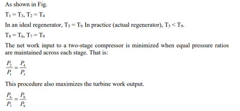
The net work output of the cycle can be increased by reducing the work input to the compressor and/or by increasing the work output from turbine (or both). Using multi-stage compression with intercooling reduces the work input the compressor. As the number of stages is increased, the compression process becomes nearly isothermal at the compressor inlet temperature, and the compression work decreases. Likewise utilizing multistage expansion with reheat (in a multi-turbine arrangement) will increase the work produced by turbines.
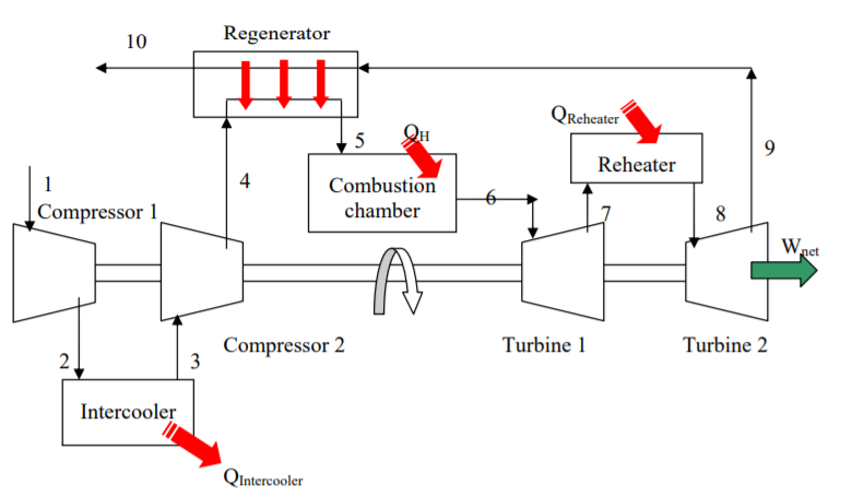
When intercooling and reheating are used, regeneration becomes more attractive since a greater potential for regeneration exists. The back work ratio of a gas-turbine improves as a result of intercooling and reheating. However; intercooling and reheating decreases thermal efficiency unless they are accompanied with regeneration.
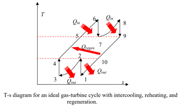
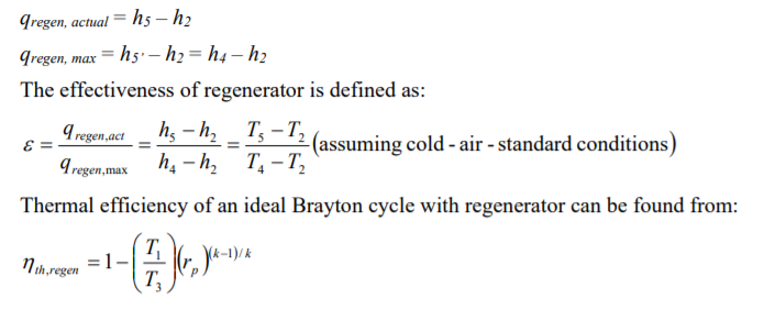
The high pressure air leaving the compressor can be heated by transferring heat from exhaust gases in a counter-flow heat exchanger which is called a regenerator.
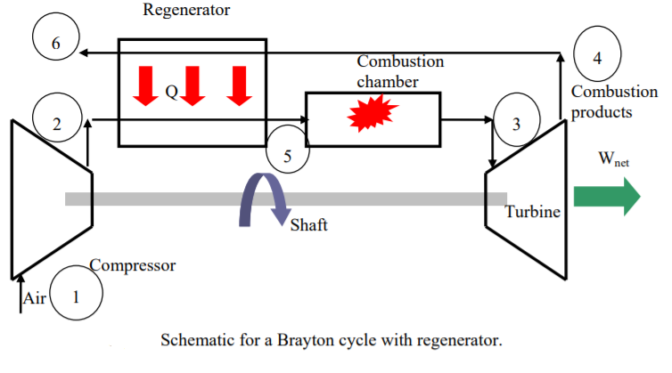
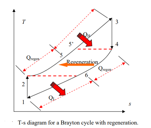
In the ideal case, the air exits the regenerator at the inlet temperature of the exhaust gases, T4. One can write:
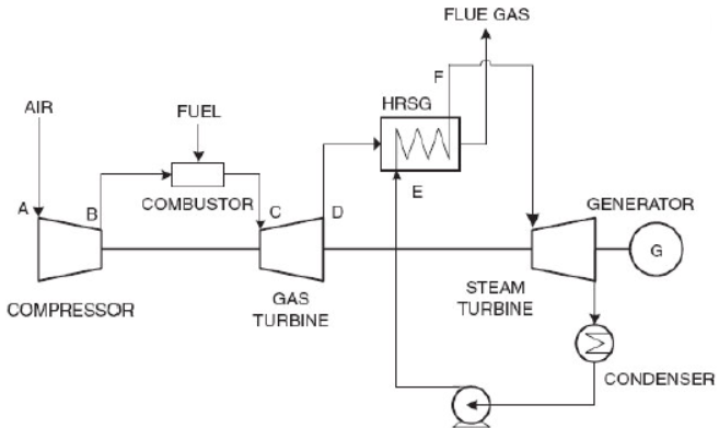
The most common type of combined cycle power plant utilizes gas turbines and is called a combined cycle gas turbine (CCGT) plant. Because gas turbines have low efficiency in simple cycle operation, the output produced by the steam turbine accounts for about half of the CCGT plant output. There are many different configurations for CCGT power plants, but typically each GT has its own associated HRSG, and multiple HRSGs supply steam to one or more steam turbines. For example, at a plant in a 2x1 configuration, two GT/HRSG trains supply to one steam turbine; likewise there can be 1x1, 3x1 or 4x1 arrangements. The steam turbine is sized to the number and capacity of supplying GTs/HRSGs.
Combined Cycle Principles of Operation
The HRSG is basically a heat exchanger, or rather a series of heat exchangers. It is also called a boiler, as it creates steam for the steam turbine by passing the hot exhaust gas flow from a gas turbine or combustion engine through banks of heat exchanger tubes. The HRSG can rely on natural circulation or utilize forced circulation using pumps. As the hot exhaust gases flow past the heat exchanger tubes in which hot water circulates, heat is absorbed causing the creation of steam in the tubes. The tubes are arranged in sections, or modules, each serving a different function in the production of dry superheated steam. These modules are referred to as economizers, evaporators, superheaters/reheaters and preheaters.
The economizer is a heat exchanger that preheats the water to approach the saturation temperature (boiling point), which is supplied to a thick-walled steam drum. The drum is located adjacent to finned evaporator tubes that circulate heated water. As the hot exhaust gases flow past the evaporator tubes, heat is absorbed causing the creation of steam in the tubes. The steam-water mixture in the tubes enters the steam drum where steam is separated from the hot water using moisture separators and cyclones. The separated water is recirculated to the evaporator tubes. Steam drums also serve storage and water treatment functions. An alternative design to steam drums is a once-through HRSG, which replaces the steam drum with thin-walled components that are better suited to handle changes in exhaust gas temperatures and steam pressures during frequent starts and stops. In some designs, duct burners are used to add heat to the exhaust gas stream and boost steam production; they can be used to produce steam even if there is insufficient exhaust gas flow.
Saturated steam from the steam drums or once-through system is sent to the superheater to produce dry steam which is required for the steam turbine. Preheaters are located at the coolest end of the HRSG gas path and absorb energy to preheat heat exchanger liquids, such as water/glycol mixtures, thus extracting the most economically viable amount of heat from exhaust gases.
The superheated steam produced by the HRSG is supply to the steam turbine where it expands through the turbine blades, imparting rotation to the turbine shaft. The energy delivered to the generator drive shaft is converted into electricity. After exiting the steam turbine, the steam is sent to a condenser which routes the condensed water back to the HRSG.
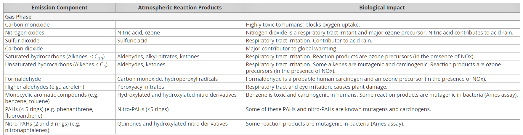
4.18 Environmental impacts of GTPP
For economic and environmental reasons, it is important that gas turbines used in both industrial power generation and also oil & gas applications can burn a wide variety of fuels, with minimum impact on the environment.
Various types of gaseous and liquid fuels that can be considered for use in industrial gas turbines such as ‘conventional’ and ‘Dry Low Emissions’. The flexibility of these systems to accept different types of fuel given due consideration to fuel quality and composition will be included along with methods employed to review and assess fuels.
Common contaminants found in fuels and the impact these have on the operability and maintenance of an industrial gas turbine will also be covered. Understanding gaseous fuel composition and the impact on the combustion process will be presented along with the resultant emissions to atmosphere and pollution abatement methods available and applied to limit the impact on the environment.
References
1. E.I.Wakil, Power Plant Engineering‖, McGraw Hill Publications New Delhi
2. P.K.Nag, Power Plant Engineering‖, McGraw Hill Publications New Delhi.
3. R.Yadav , Steam and Gas Turbines‖ ,Central Publishing House, Allahabad.
4. G.D.Rai, Non-Conventional Energy Sources, Khanna Publishers,Delhi
5. S.P.Sukhatme, Solar Energy‖ Tata McGraw-Hill Publications, New Delhi
6. G R Nagpal Power Plant Engineering , Khanna Publication


