Unit 5
Non-Conventional Power Plants
A solar power plant is based on the conversion of sunlight into electricity, either directly using photo voltaic (PV), or indirectly using concentrated solar power (CSP).
Concentrated solar power systems use lenses, mirrors, and tracking systems to focus a large area of sunlight into a small beam. Photo voltaics converts light into electric current using the photoelectric effect.
Applications:
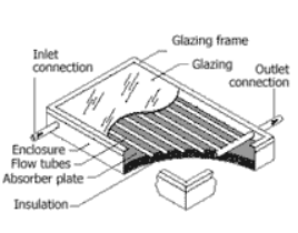
The main use of this technology is in residential buildings where the demand for hot water has a large impact on energy bills.
Solar ponds are large-scale energy collectors with integral heat storage for supplying thermal energy.
The solar pond works on a very simple principle. It is well-known that water or air is heated they become lighter and rise upward e.g. a hot air balloon. Similarly, in an ordinary pond, the sun’s rays heat the water and the heated water from within the pond rises and reaches the top but loses the heat into the atmosphere. The net result is that the pond water remains at the atmospheric temperature. The solar pond restricts this tendency by dissolving salt in the bottom layer of the pond making it too heavy to rise.
A solar pond has three zones. The top zone is the surface zone, or UCZ (Upper Convective Zone), which is at atmospheric temperature and has little salt content. The bottom zone is very hot, 70°– 85° C, and is very salty. It is this zone that collects and stores solar energy in the form of heat, and is, therefore, known as the storage zone or LCZ (Lower Convective Zone). Separating these two zones is the important gradient zone or NCZ (Non-Convective Zone). Here the salt content increases as depth increases, thereby creating a salinity or density gradient. If we consider a particular layer in this zone, water of that layer cannot rise, as the layer of water above has less salt content and is, therefore, lighter. Similarly, the water from this layer cannot fall as the water layer below has a higher salt content and is, therefore, heavier. This gradient zone acts as a transparent insulator permitting sunlight to reach the bottom zone but also entrapping it there. The trapped (solar) energy is then withdrawn from the pond in the form of hot brine from the storage zone.
Though solar ponds can be constructed anywhere, it is economical to construct them at places where there is low cost salt and bittern, good supply of sea water or water for filling and flushing, high solar radiation, and availability of land at low cost. Coastal areas in Tamil Nadu, Gujarat, Andhra Pradesh, and Orissa are ideally suited for such solar ponds.
Applications:
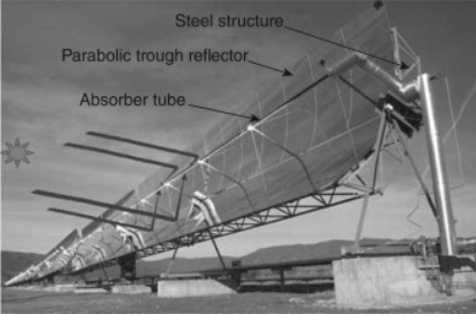
A parabolic-trough collector (PTC) is a linear-focus solar collector, basically composed of a parabolic-trough-shaped concentrator that reflects direct solar radiation onto a receiver or absorber tube located in the focal line of the parabola.
The larger collector aperture area concentrates reflected direct solar radiation onto the smaller outer surface of the receiver tube, heating the fluid that circulates through it.
The solar radiation is thus transformed into thermal energy in the form of sensible or latent heat of the fluid.
This thermal energy can then be used to feed either industrial processes demanding thermal energy (e.g., food industry, petro-chemical industry, etc.) or Rankine cycles to produce electricity with a steam turbine in a ‘solar thermal’ power plant.
5.5 Heliostat
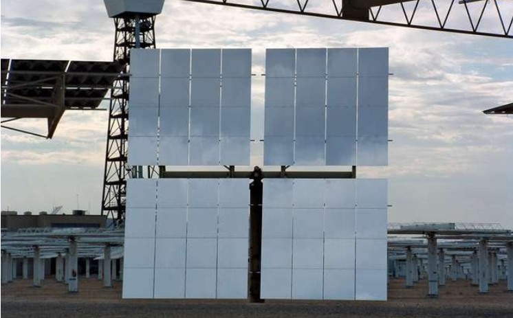
It is used in solar telescopes to orient and focus sunlight along a fixed direction. A typical heliostat consists of a flat plane mirror and a curved parabolic mirror. The plane mirror is mounted along an axis parallel (i.e., equatorial) to Earth and rotated slowly by a motor to reflect light from the Sun. The parabolic mirror focuses the reflected rays into the telescope along a fixed direction while the Sun traverses the sky. Therefore, as the telescope’s field of view rotates, different celestial objects move quickly into view.
Portable heliostats are useful in studying solar eclipses because they eliminate the need to mount telescopes equatorially. Larger models, installed at permanent positions around the world, have also been employed to track both the Sun and the stars.
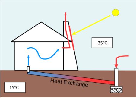
A solar chimney is a type of passive solar heating and cooling system that can be used to regulate the temperature of a building as well as providing ventilation. Like a Trombe wall or solar wall, solar chimneys are a way to achieve energy efficient building design. Essentially, solar chimneys are hollow containers that connect the inside part of the building to the outside part of the building.
Solar chimneys are easy and inexpensive means to heat and ventilate a building. First, a chimney is built and coated in some dark or black material. It is coloured black because this minimizes the amount of sunlight that is reflected off of the chimney, absorbing more of the heat and ensuring more of the heat is transferred to the air inside the building. As well, these chimneys are generally placed on a South facing wall if the home is in the Northern hemisphere.
The process of heating a space using a solar chimney is fairly simple. When the solar radiation hits the side of the chimney, the column of air inside the chimney is heated. If the top exterior vents of the chimney are closed, the heated air is forced back into the living space. This provides a type of convective air heating. As the air cools in the room it is pulled back into the solar chimney, heating once again. When solar chimneys are used for heating, they operate similarly to Trombe walls.
Cooling a space using a solar chimney is slightly different than cooling using a Trombe wall. Since a roof overhand cannot be installed in addition to a solar chimney, two additional vents are present. The first vent has been mentioned, the one at the top of the chimney.
The second is at the opposite end of the building, providing an opening between the building and outside air to allow for ventilation. When solar radiation hits the side of the chimney, the column of air inside the chimney is again heated. The vent at the top of the chimney is kept open so this heated air is not trapped. This heated air is pulled up and out of the chimney, pulling new air in from the outside and creating a sort of "draft" that provides cool, fresh air into the building.
5.7 SPV cell based plants- working principal
Electrical energy can be harvested from solar power by means of either photovoltaics or concentrated solar power systems.
Photovoltaics (PV)
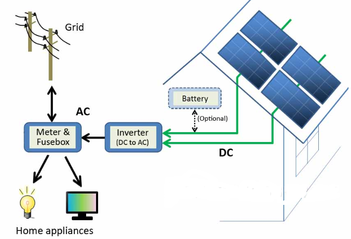
Photovoltaics directly convert solar energy into electricity. They work on the principle of the photovoltaic effect. When certain materials are exposed to light, they absorb photons and release free electrons. This phenomenon is called as the photoelectric effect. Photovoltaic effect is a method of producing direct current electricity based on the principle of the photoelectric effect.
Based on the principle of photovoltaic effect, solar cells or photovoltaic cells are made. They convert sunlight into direct current (DC) electricity. But, a single photovoltaic cell does not produce enough amount of electricity. Therefore, a number of photovoltaic cells are mounted on a supporting frame and are electrically connected to each other to form a photovoltaic module or solar panel. Commonly available solar panels range from several hundred watts (say 100 watts) up to few kilowatts (ever heard of a 5kW solar panel?). They are available in different sizes and different price ranges. Solar panels or modules are designed to supply electric power at a certain voltage (say 12v), but the current they produce is directly dependent on the incident light. As of now it is clear that photovoltaic modules produce DC electricity. But, for most of the times we require AC power and, hence, solar power system consists of an inverter too.
According to the requirement of power, multiple photovoltaic modules are electrically connected together to form a PV array and to achieve more power. There are different types of PV systems according to their implementation.
5.9 Applications
(a) Solar water heating
(b) Solar heating of buildings
(c) Solar distillation
(d) Solar pumping
(e) Solar drying of agricultural and animal products
(f) Solar furnaces
(g) Solar cooking
(h) Solar electric power generation
(i) Solar thermal power production
(j) Solar green houses.
Geothermal power plants are used in order to generate electricity by the use of geothermal energy (the Earth's internal thermal energy). They essentially work the same as a coal or nuclear power plant, the main difference being the heat source. With geothermal, the Earth's heat replaces the boiler of a coal plant or the reactor of a nuclear plant.
Hot water or steam is extracted from the Earth through a series of wells and feeds the power plant. In most geothermal plants the water pulled up from the ground is returned back to the subsurface. The rate of water used is often larger than the rate of water returned, so make-up water supplies are generally needed.
5.10.1 Superheated steam system
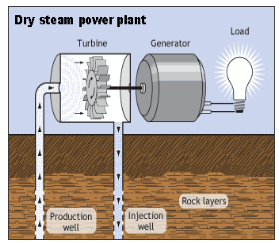
Dry steam reservoirs use the water in the earth's crust, which is heated by the mantle and released through vents in the form of steam. The dry steam power plant is suitable where the geothermal steam is not mixed with water. Production wells are drilled down to the aquifer and the superheated, pressurized steam (180°-350°C) is brought to the surface at high speeds, and passed through a steam turbine to generate electricity. In simple power plants, the low pressure steam output from the turbine is vented to the atmosphere, but more commonly, the steam is passed through a condenser to convert it to water. This improves the efficiency of the turbine and avoids the environmental problems caused from the direct release of steam into the atmosphere.
The waste water is then reinjected into the ground with reinjection wells.
The underground water reservoirs that feed such a system are refilled when rain falls on the land. The rainwater eventually soaks back into the crust of the earth. Because this occurs on a continuous basis, geothermal energy is considered a renewable resource.
This is the oldest type of geothermal power plant. It was first used at Lardarello in Italy where it has powered electric railroads for since 1904. About 6 percent of the energy used in northern California is produced at 28 dry steam reservoir plants found at The Geysers dry steam fields in northern California. At peak production, these dry steam geothermal power plants are the world's largest single source of geothermal power producing up to 2,000 megawatts of electricity an hour. That is about twice the amount of electricity a large nuclear power plant can produce. These dry steam power plants emit only excess steam and very minor amounts of gases.
5.10.2 Flash type
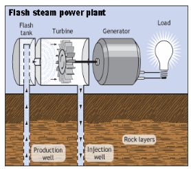
Flash steam plants are the most common type of geothermal power generation plants in operation in the world today. Fluid at temperatures greater than 360°F (182°C) is pumped under high pressure into a tank at the surface held at a much lower pressure, causing some of the fluid to rapidly vaporize, or "flash." The vapor then drives a turbine, which drives a generator. If any liquid remains in the tank, it can be flashed again in a second tank to extract even more energy.
Flash steam plants take high-pressure hot water from deep inside the earth and convert it to steam to drive generator turbines. When the steam cools, it condenses to water and is injected back into the ground to be used again. Most geothermal power plants are flash steam plants.
5.10.3 Binary cycle plant
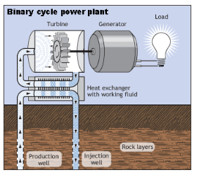
Binary cycle power plants transfer the heat from geothermal hot water to another liquid. The heat causes the second liquid to turn to steam, which is used to drive a generator turbine.
5.11 Tidal Power Plant
5.11.1 Components
(i) Dam
The function of a dam is to form a barrier between the sea and the basin or between one basin to the other basin in case of multiple basins. The most suitable word for tidal power plant is barrage. Barrages have to resist waves whose shock can be severe and where pressure changes sides continuously.
(ii) Sluice ways from basin to sea and vice versa
The sluice ways are gate controlled devices. They are employed to fill the basin during the high tide or empty the basin during low tide. In existing plants, vertical lift gates have been employed. Flap gates are also used. The flap gates allow only in the direction of sea to basin. Therefore, the level of the basin rises.
(iii) Power house.
Auxiliary equipments, turbines and generators are the main components of the power house. Large sized turbines are used because of low head available. Bulb types and rim type turbines are commonly used. Shaft turbines are also under steady.
5.11.2 Single basin
Single basin system can generate power only intermittently. This is the simplest system of generating tidal power. The single basin scheme has only one basin. The basin is separated from the sea by a dam (barrage, Dyke). The sluice way is opened during high tide to fill the basin. The turbine-generator units are mounted within the ducts inside the barrage.
The single basin system can be further classified as:
(i) Single Ebb-Cycle System:
In single ebb-cycle system, when the high tides (flood side) are falling, sluices are opened to permit the sea water to enter the basin, while the turbine sets are shut. The level of the basin begins increasing. The energy is stored in the form of tidal range. Tidal range provides water head during low tides. The generation of power takes place, when the water from the basin flows over the turbine into the low level sea water. The turbines are designed for single way operation. The power output from such system is intermittent in nature and highly variable.
(ii) Single Tide-Cycle System:
In single tide cycle system, the generation is affected when the sea is at flood tide. The sea water is admitted into the basin over the turbines. As the flood tide period is over and the sea level begins falling again, the generation is stopped. The basin is drained into the sea through the sluice ways. In this system also the power output is intermittent.
(iii) Double Cycle System:
In double cycle system, the reversible turbines are installed and power is generated during filling and emptying of basin. Filling process occurs when the ocean is at high tide while the water in basin at low tide level, the emptying occurs when the ocean is at low tide and basin at high tide level.
The flow of water in both directions is used to drive the reversible turbines. Each turbine drives the generator. In this system also continuous generation of power is not possible because of short duration. Electric power is generated during two short periods, during each tidal period of 12 hours 25 minutes or once every 6 hours and 12.5 minutes.
5.11.3 Double basin systems
There are two basins at different levels. A dam is provided between two basins. The turbines are located in the dam. The sluice gates are provided in the dam. One basin is called the upper basin; the water level is maintained above that in the other, the low basin. The high level basin gates are called the inlet gates and low level gates as outlet gates. The upper basin is filled with water.
When the water level in upper basin A provides a sufficient difference of head between the two basins, the turbines are started. The water flows from basin A to basin B through the turbines and the power is generated. The power generation thus continues simultaneously along with filling up of water in basin A. When the tide attains its peak value, the water level in basin A is maximum; the inlet sluices are then closed. The water flows from the upper basin to the lower basin through the turbines.
Thus, the water level in the upper basin falls and that in the lower basin rises. When the rising level in lower basin B becomes equal to the level of the falling tide, the outlet sluices are opened. When the tide reaches its lower most level, the outlet gates are closed. After some time the tide rises. When its level becomes equal to low level of the upper basin, the inlet gates are opened. Consequently the level of water in basin A starts rising. Thus, the cycle is repeated.
Two basin schemes have the advantages over normal schemes is that generation time can be adjusted with high flexibility and it is also possible to generate almost continuously. In normal estuarine situations, however, two basin schemes are very expensive to construct due to the cost of extra length of barrage. There are some favourable geographies, however, which are well suited to this type of scheme.
It uses the ocean thermal gradient between cooler deep and warmer shallow or surface seawaters to run a heat engine and produce useful work, usually in the form of electricity. OTEC can operate with a very high capacity factor and so can operate in base load mode.
The denser cold water masses, formed by ocean surface water interaction with cold atmosphere in quite specific areas of the North Atlantic and the Southern Ocean, sink into the deep sea basins and spread in entire deep ocean by the thermohaline circulation. Upwelling of cold water from the deep ocean is replenished by the down welling of cold surface sea water.
5.12.1 principal of working
5.12.2 Claude cycle
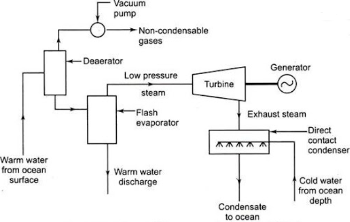
In this system, the warm water is converted into ‘steam’ in an evaporator. The steam drives steam-turbine generator to deliver electrical energy.
The warm water from ocean surface is admitted through a ‘deaerator’ to the ‘flash evaporator’ which is maintained under high vacuum. As a result, low pressure steam is generated due to throttling effect and the remainder warm water is discharged back to the ocean at high depth.
The deaerator also removes the dissolved non-condensable gases from water before supplied to the evaporate.
The low pressure steam having very high specific volume is supplied to ‘turbine’ where it expands and the mechanical power so developed is converted into electric power by the ‘generator’.
The exhaust steam, from turbine is discharged into a direct contact type condenser where it mixes with cold water drawn from ocean at a depth of about 1 to 2 km. The mixture of condensed steam and ocean cold water are discharged into the ocean.
Advantages of Open Cycle System:
1. The warm Ocean water is flash evaporated and the need for having a surface heat exchanger is eliminated.
2. The portable water is obtained when the exhaust steam from the turbine is condensed.
Disadvantages of Open Cycle System:
1. As the steam is generated at very low pressure (0.02 bar approx.) the volume of steam to be handled is very large, leading to a very large diameter for the steam turbine. (Example- A 1 MW OTEC plant requires a steam turbine of 12 m in diameter.)
2. To maintain the vacuum in the flash evaporator, massive vacuum pumps will be required.
3. The plant cost is high.
4. The plant is subjected to extremely reverse stresses.
5.12.3 Anderson Cycle
The closed cycle OTEC concept was proposed by ‘Barjot’ in 1926. The cycle was further developed by ‘Anderson’ in 1992.
All the systems being proposed for construction, now work on “Closed Rankine cycle” (Anderson cycle, vapour cycle) and use low boiling point working fluids like ammonia, propane, freon (R-12, R-22) etc. These systems will be located off-sore on large floating platforms or inside floating hulls.
The warm surface water is used for supplying the heat input in the ‘boiler’, while cold water brought up from ocean depths is used for extracting the heat in the ‘condenser’.
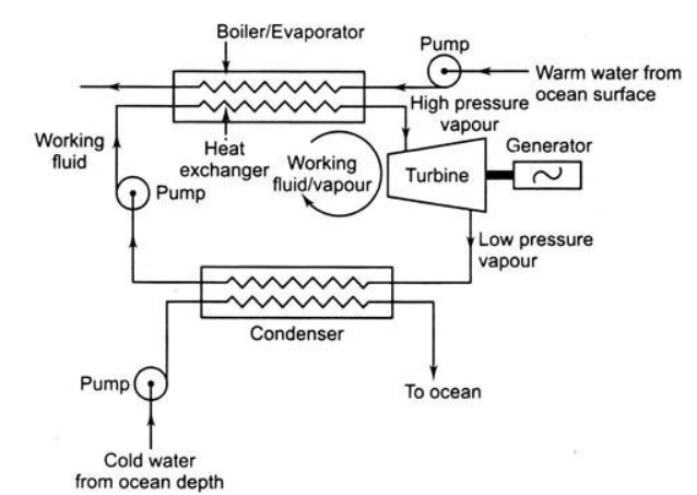
Working of Closed Cycle System:
i. Warm water from ocean surface is circulated through a pump to a ‘heat exchanger’ which acts as a ‘boiler’ to generate working fluid ammonia vapour at high pressure.
ii. This vapour expands in the ‘turbine’ to develop mechanical power, which in turn runs an electric ‘generator’ to produce electric power.
iii. The working vapour from turbine at low pressure is condensed in the ‘condenser’ with the help of cold water drawn from the depth of ocean through a pump.
The overall efficiency of such a plant is very low in the range of 2 to 3% only. Inspite of this, the concept of an OTEC system seems to be economically attractive because both the collection and storage of solar energy is being done free by nature.
The “major advantage” of this system is that fluid evaporates at around 25°C and does not require vacuum pumps. The pressure at the turbine will be of the order of 9 to 6 bar resulting in compact turbines
Magneto hydrodynamic power generation provides a way of generating electricity directly from a fast moving stream of ionised gases without the need for any moving mechanical parts - no turbines and no rotary generators. Several MHD projects were initiated in the 1960s but overcoming the technical challenges of making a practical system proved very expensive. Interest consequently waned in favour of nuclear power which since that time has seemed a more attractive option.
MHD power generation has also been studied as a method for extracting electrical power from nuclear reactors and also from more conventional fuel combustion system.
5.13.1 Principal of working
The MHD generator can be considered to be a fluid dynamo. This is similar to a mechanical dynamo in which the motion of a metal conductor through a magnetic field creates a current in the conductor except that in the MHD generator the metal conductor is replaced by a conducting gas plasma.
When a conductor moves through a magnetic field it creates an electrical field perpendicular to the magnetic field and the direction of movement of the conductor.
This is the principle, discovered by Michael Faraday, behind the conventional rotary electricity generator. Dutch physicist Antoon Lorentz provided the mathematical theory to quantify its effects.
The flow (motion) of the conducting plasma through a magnetic field causes a voltage to be generated (and an associated current to flow) across the plasma , perpendicular to both the plasma flow and the magnetic field according to Fleming's Right Hand Rule
Lorentz Law describing the effects of a charged particle moving in a constant magnetic field can be stated as
F = QvB
where
F is the force acting on the charged particle
Q is charge of particle
v is velocity of particle
B is magnetic field
5.13.2 Open Cycle MHD generator
The MHD generator needs a high temperature gas source, which could be the coolant from a nuclear reactor or more likely high temperature combustion gases generated by burning fossil fuels, including coal, in a combustion chamber. The diagram below shows possible system components.
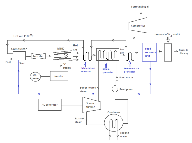
The expansion nozzle reduces the gas pressure and consequently increases the plasma speed (Bernoulli's Law) through the generator duct to increase the power output (See Power below). Unfortunately, at the same time, the pressure drop causes the plasma temperature to fall (Gay-Lussac's Law) which also increases the plasma resistance, so a compromise between Bernoulli and Gay-Lussac must be found.
The exhaust heat from the working fluid is used to drive a compressor to increase the fuel combustion rate but much of the heat will be wasted unless it can be used in another process.
The Plasma
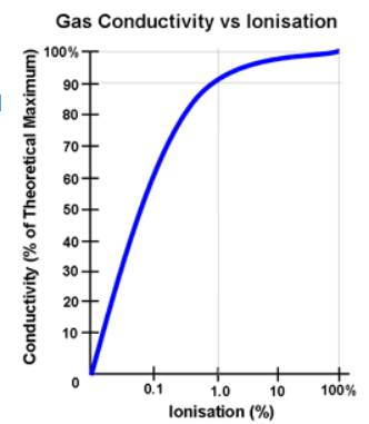
The prime MHD system requirement is creating and managing the conducting gas plasma since the system depends on the plasma having a high electrical conductivity. The plasma can be likened to the fourth state of matter after the solid, liquid and gaseous states, in which the atoms or molecules are stripped of their electrons leaving positively charged ions. Suitable working fluids are gases derived from combustion, noble gases, and alkali metal vapours.
The Gas Plasma To achieve high conductivity, the gas must be ionised by detaching the electrons from the atoms or molecules leaving the positively charged plasma. The plasma flows through the magnetic field at high speed, in some designs, more than the speed of sound, the flow of the positively charged particles providing the moving electrical conductor necessary for inducing a current in the external electrical circuit..
Methods of Ionising the Gas Various methods for ionising the gas are available, all of which depend on imparting sufficient energy to the gas. It may be accomplished by heating or irradiating the gas with X rays or Gamma rays. It has also been proposed to use the coolant gases such as helium and carbon dioxide employed in some nuclear reactors as the plasma fuel for direct MHD electricity generation rather than extracting the heat energy of the gas through heat exchangers to raise steam to drive turbine generators. Seed materials such as Potassium carbonate or Cesium are often added in small amounts, typically about 1% of the total mass flow to increase the ionisation and improve the conductivity, particularly of combustion gas plasmas.
Containment Since the plasma temperature is typically over 1000 °C, the duct containing the plasma must be constructed from non-conducting materials capable of withstanding these high temperatures. The electrodes must of course be conducting as well as heat resistant .
|
5.13.3 Closed cycle MHD generators
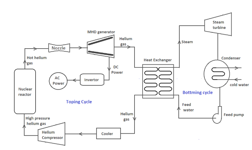
A closed cycle MHD system using helium or argon gas seeded with Cesium is shown in Figure. Step by step working of the system is as under:
In this system, helium gas seeded with Cesium is heated to a very high temperature in a nuclear reactor.
The hot helium gas is passed through a nozzle to increase its velocity and then supplied to MHD duct to produce DC power. Here, some part of the internal energy of the gas is directly converted into DC power.
In next step, the gas is passed through the heat exchanger (i.e. steam generator) to convert feed water into steam. Now, this steam is used in a conventional steam power plant to generate electricity.
5.14 Fuel cell
A fuel cell is a device that generates electricity by a chemical reaction. Every fuel cell has two electrodes called, respectively, the anode and cathode. The reactions that produce electricity take place at the electrodes.
Every fuel cell also has an electrolyte, which carries electrically charged particles from one electrode to the other, and a catalyst, which speeds the reactions at the electrodes.
Hydrogen is the basic fuel, but fuel cells also require oxygen. One great appeal of fuel cells is that they generate electricity with very little pollution–much of the hydrogen and oxygen used in generating electricity ultimately combine to form a harmless byproduct, namely water.
One detail of terminology: a single fuel cell generates a tiny amount of direct current (DC) electricity. In practice, many fuel cells are usually assembled into a stack. Cell or stack, the principles are the same.
5.14.1 Alkaline
5.14.2 Acidic
5.14.3 Proton-exchange membrane
Wind is a form of solar energy. Winds are caused by the uneven heating of the atmosphere by the sun, the irregularities of the earth's surface, and rotation of the earth. Wind flow patterns are modified by the earth's terrain, bodies of water, and vegetative cover. This wind flow, or motion energy, when "harvested" by modern wind turbines, can be used to generate electricity.
How Wind Power Is GeneratedIt is used to generate mechanical power or electricity. Wind turbines convert the kinetic energy in the wind into mechanical power. This mechanical power can be used for specific tasks (such as grinding grain or pumping water) or a generator can convert this mechanical power into electricity to power homes, businesses, schools, and the like.
5.15.1 Wind availability
The availability factor of a power plant is the amount of time that it is able to produce electricity over a certain period, divided by the amount of the time in the period. Occasions where only partial capacity is available may or may not be deducted. Where they are deducted, the metric is titled equivalent availability factor (EAF). The availability factor should not be confused with the capacity factor. The capacity factor for a given period can never exceed the availability factor for the same period. The difference arises when the plant is run at less than full capacity, in which case the capacity factor is less than the availability factor.
5.15.2 Wind mills and subsystems
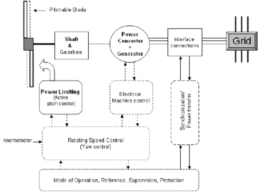
The simplest possible wind-energy turbine consists of three crucial parts:
5.15.3 Classification of wind turbines
Wind turbines, like aircraft propeller blades, turn in the moving air and power an electric generator that supplies an electric current. Simply stated, a wind turbine is the opposite of a fan. Instead of using electricity to make wind, like a fan, wind turbines use wind to make electricity. The wind turns the blades, which spin a shaft, which connects to a generator and makes electricity.
Wind Turbine TypesModern wind turbines fall into two basic groups; the horizontal-axis variety, like the traditional farm windmills used for pumping water, and the vertical-axis design, like the eggbeater-style Darrieus model, named after its French inventor. Most large modern wind turbines are horizontal-axis turbines.
5.15.4 Operating characteristics
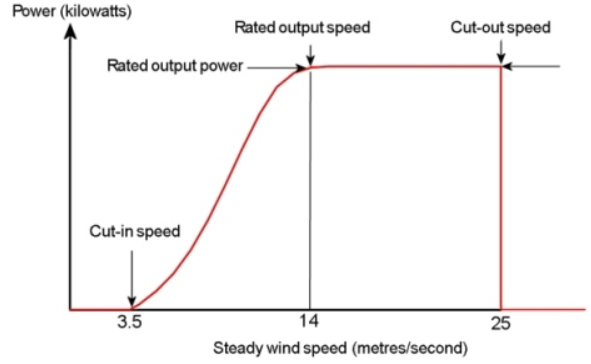
Cut-in speed.
The speed at which the turbine first starts to rotate and generate power is called the cut-in speed and is typically between 3 and 4 metres per second.
Rated output power and rate output wind speed.
As the wind speed rises above the cut-in speed, the level of electrical output power rises rapidly as shown. However, typically somewhere between 12 and 17 metres per second, the power output reaches the limit that the electrical generator is capable of. This limit to the generator output is called the rated power output and the wind speed at which it is reached is called the rated output
wind speed.
Cut-out speed.
As the speed increases above the rate output wind speed, the forces on the turbine structure continue to rise and, at some point, there is a risk of damage to the rotor. As a result, a braking system is employed to bring the rotor to a standstill. This is called the cut-out speed and is usually around 25 metres per second.
Wind turbine efficiency or power coefficient.
The efficiency, μ is called as the power coefficient, cp, of the wind turbine is simply defined as the actual power delivered divided by the available power.

The Betz limit on wind turbine efficiency.
There is a theoretical limit on the amount of power that can be extracted by a wind turbine from an airstream. It is called the Betz limit and is given by
μ=16/27≈ 59%
5.15.5 Wind solar hybrid power plants
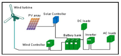
According to many renewable energy experts, a small "hybrid" electric system that combines home wind electric and home solar electric (photovoltaic or PV) technologies offers several advantages over either single system.
In much of the United States, wind speeds are low in the summer when the sun shines brightest and longest. The wind is strong in the winter when less sunlight is available. Because the peak operating times for wind and solar systems occur at different times of the day and year, hybrid systems are more likely to produce power when you need it.
Many hybrid systems are stand-alone systems, which operate "off-grid" -- not connected to an electricity distribution system. For the times when neither the wind nor the solar system are producing, most hybrid systems provide power through batteries and/or an engine generator powered by conventional fuels, such as diesel. If the batteries run low, the engine generator can provide power and recharge the batteries.
Adding an engine generator makes the system more complex, but modern electronic controllers can operate these systems automatically. An engine generator can also reduce the size of the other components needed for the system. Keep in mind that the storage capacity must be large enough to supply electrical needs during non-charging periods. Battery banks are typically sized to supply the electric load for one to three days.
5.15.6 Challenges in commercialization of nonconventional power plants
References :
1. E.I.Wakil, Power Plant Engineering‖, McGraw Hill Publications New Delhi
2. P.K.Nag, Power Plant Engineering‖, McGraw Hill Publications New Delhi.
3. R.Yadav , Steam and Gas Turbines‖ ,Central Publishing House, Allahabad.
4. G.D.Rai, Non-Conventional Energy Sources, Khanna Publishers,Delhi
5. S.P.Sukhatme, Solar Energy‖ Tata McGraw-Hill Publications, New Delhi
6. G R Nagpal Power Plant Engineering , Khanna Publication
