Unit 6
Instrumentation and Economics of Power Plant
The main items of the electrical power plant are
Generators convert mechanical or chemical energy into electrical energy. They do this by capturing the power of motion and turning it into electrical energy by forcing electrons from the external source through an electrical circuit. A generator is essentially an electrical motor working in reverse.
There are nine parts to a generator and they are:
Engine. The engine supplies energy to the generator. The power of the engine determines how much electricity a generator can provide.
Alternator. This is where the conversion from mechanical energy to electrical energy occurs. Also called a “genhead”, the alternator contains both moving and stationary parts that work together to create the electromagnetic field and movement of electrons that generates electricity.
Fuel System. The fuel system makes it possible for the generator to produce the energy needed. The system includes a fuel tank, a fuel pump, a pipe connecting the tank to the engine, and a return pipe. A fuel filter removes debris before it gets to the engine and an injector forces the fuel into the combustion chamber.
Voltage Regulator. This component helps control the voltage of the electricity that is produced. It also helps convert the electricity from AC to DC, if needed.
Cooling and Exhaust Systems. Generators create a lot of heat. The cooling system ensures the machine doesn’t overheat. The exhaust system direct and remove the fumes the form during operation.
Lubrication System. There are many small, moving parts inside a generator. It is essential to lubricate them adequately with engine oil to ensure smooth operation and protect them from excess wear. Lubricant levels should be checked regularly, as often as every 8 hours of operation.
Battery Charger. Batteries are used to start up the generator. The battery charger is a fully automatic component that ensures the battery is ready to go when needed by supplying it with a constant low-level of voltage.
Control Panel. The control panel controls every aspect of generator operation from start up and running speed to outputs. Modern units are even capable of sensing when power dips or goes out and can start or shut off the generator automatically.
Main Assembly / Frame. This is the body of the generator. It is the part that we see; the structure that holds it all in place.
The excitation system is required to provide the necessary field current to the rotor winding of a synchronous machine. The availability of excitation at all times is of paramount importance. Loss of excitation of a unit on the bus results in a more serious disturbance than that resulting from outage of the generator unit from the bus, as the remaining units must not only pick up the load dropped but also supply the large reactive current drawn by the unexcited alternator. In view of this an excitation system with better reliability is preferable, even if the initial cost is more.
The main requirements of an excitation system are reliability under all conditions of service, simplicity of control, ease of maintenance, stability and fast transient response.
The amount of excitation required depends on the load current, load power factor and speed of the machine. Larger the load currents, lower the speeds and lagging power factors, more the excitation required.
An excitation system may be individual one, in which each alternator is provided with its own exciter in the form of small generator on an extension of the main shaft, or centralized excitation system having two or more exciters feeding a bus-bar to which field systems of all the alternators in the power plant are connected.
Though centralized excitation system is a cheaper arrangement but a fault in this system adversely affects all the alternators in the power plant. As such individual excitation system is widely used.
Most generators have numerous conductors, all of which produce heat as current flows through them. That heat can build up quickly within the system and it must be properly removed to reduce the risk of damage.
If heat is not properly removed from the system, damage to the windings occurs rather quickly. A number of issues can occur including clearance and balance problems. But, it is possible to reduce this heat significantly through various cooling systems. By consistently cooling the generator, it is possible to minimize the risk of any damage to the generator itself. Ultimately, this reduces frustration and prevents the need for repairs.
Air-Cooled Systems
Knowing the value of cooling generators, it is then important to understand how the best air-cooled systems work. For air-cooled systems, there are two main methods of cooling available.
The first is open-ventilated systems. Here, the air in the atmosphere is used with a type of exhaust system. This allows for the air to be released right back into the atmosphere. It pulls in the air and pushes it back out into the surrounding area.
The second type is an enclosed system. An enclosed system, as the name implies, keeps the air in place. It works to then recirculate the air. As it does, the air is cooled which, in turn, keeps the generator cool.
Air cooled systems have some limits including the risk of overheating. However, air cooled systems are mostly restricted to small standby and portable generators that produce up to 22 kilowatts of power per unit.
Liquid-Cooled Systems
Liquid-cooled systems, sometimes referred to as water-cooled systems, are another option. There are numerous types of liquid-cooled systems. Some operate using oil while others use coolants. Hydrogen is another cooling element.
A liquid-cooled system features a water pump that moves the coolant around the engine using a number of hoses. The heat from the generator transfers naturally to the coolant, cooling the unit. This type of system is best for larger generators in particular. They require more heavy duty components to keep the generator cool. This does increase the cost, but these are the most common option for commercial and industrial use.
One key option is the hydrogen-cooled system. These are also used for large generators. The hydrogen used in them has a high thermal conductivity. This allows these systems to pull out heat at a faster rate. As a result, they work well for larger systems that cannot be efficiently cooled using other coolants.
A short circuit is when there is a low resistance connection between two conductors that are supplying electrical power to a circuit. This would generate an excess of voltage streaming and cause excessive flow of current in the power source. The electricity will flow through a ‘short’ route and cause a short circuit.
TYPES
1. Normal Short Circuit
This is when a hot wire carrying current touches a neutral wire. When that happens, the resistance will go down instantly and a large volume of current will flow through an unexpected pathway.
2. Ground Fault Short Circuit
Ground fault short circuit occurs when the hot wire carrying current comes into contact with some grounded portion of the system. It can be a grounded metal wall box, bare ground wire or a grounded portion of an appliance.
CAUSES
Faulty Circuit Wire Insulation
If the insulation is damaged or old, it may allow the hot wires to touch with neutral. This will cause a short circuit.
Age of the wire, nails or screws can damage the insulation and allow short circuit. There is a risk of pests of gnawing the insulation and exposing the wire conductors too.
Loose Wire Connections
If there are any loose wire connections or attachments, it will allow the live and neutral wires to touch. If you see faulty wire connections, do not try to fix it on your own and call a professional immediately.
Faulty Appliance Wiring
If you plug an appliance into a wall socket, its wiring essentially becomes an extension of the circuit. Therefore, if there are any problems in the appliance wiring, it will become circuit problems.
Short circuits can occur in the power cords, plugs or inside the appliance. Make sure you get short circuit protection for all the appliances.
LIMITING METHODS
Monitor Outlets & Appliances
Use Less Electricity During Storms
Get a Yearly Electrical Inspection
Install Devices that Prevent Short Circuit
2. Ground-Fault Circuit Interrupters (GFCIs): GFCI works by comparing the amount of current flowing in and out of a circuit. If there is a ground fault or imbalance between the currents flowing in and out, the GFCI will shut off electrical power.
3. Arc-Fault Circuit Interrupters (AFCIs): An AFCI breaks the circuit when it detects an electric arc in the circuit. It helps in preventing electrical fires.
Switchgear is an apparatus which is used for switching, controlling and protecting electrical circuits and equipment. The requirement of electric power has increased a lot, so in order to get a continuous power supply. Power system must be protected from large faults and provide protection to machinery and devices. For the continuity of the power supply machinery such as generators and motors are switched on and off many times and the means provide to achieve this is called switchgear.
In general, switchgear is the term including the entire range of switching devices and their combination with associated control, measuring, protecting, and regulating equipment.
Functions
Components
(A) Earthling to Water Main:
First the cold water pipe is thoroughly cleared of all grease and dirt. An adjustable clip is fixed at the cleaned spot. One end of the earthling cable is fixed to a lug which is attached to the clip by a fixing bolt and nut, tightening the nut draws the clip tight to grip the pipe firmly. The other end of the earthling cable is similarly connected to the conduit with a clamp and lug.
(B) Pipe Earthling:
A galvanized iron pipe 38 mm in diameter and 2 meter long is driven into the ground or a copper plate of adequate size buried edge wise in the earth is used as the earth electrode. Its resistance must be kept below specified limit, packir % salts and powdered coke or charcoal to a depth of 30 cm, all around the pipe in low resistance, keeping the earth moist by pouring water in to the pipe.
(C) Plate Earthling:
The earth connection can be provided with the help of a copper/G.I. plate. When G.I. plate is used it should not be of less than 60 cm x 60 cm x 6.35 mm.
The plate is kept with its face vertical at a depth of 3 m and is so arranged that it is embedded in an alternate layer of coke and salt for a minimum thickness of about 15 cm in case earthling is done by copper plate and in coke layer of 15 cm if it is done with GL Plate- The earth wire is securely bolted t0 the earth plate with the help of bolt nut and washer.
A device used to protect equipment, machinery, components and devices, in electrical and electronic circuit, against short circuit, over current and earth fault, is called as protective devices.
Protective devices are necessary to protect electrical appliance or equipment against
a) Short Circuit
b) Abnormal variations in the supply voltage
c) Overloading of equipment
d) To protect operator against accidental contact with the faulty equipment, falling which the operator may get a severe shock.
Types of Protective Device
1.Fuse Wire or Fuse
2.MCB – Miniature circuit breaker
3.ELCB – Earth Leakage Circuit Breaker
4.ELCB & MCB
5.Earthing or Grounding
DC power measurement is relatively simple as the equation is simply watts = volts x amps. For AC power measurement, the power factor (PF) introduces complexity as watts = volts x amps x PF. This measurement of AC power is referred to as active power, true power or real power. In AC systems, multiplying volts x amps = volt-amps, also called apparent power.
Power consumption is measured by calculating it over time, using at least one complete cycle. Using digitizing techniques, the instantaneous voltage is multiplied by the instantaneous current then accumulated and integrated over a specific time period to provide a measurement. This method provides a true power measurement and true RMS measurements for any waveform, sine or distorted, including harmonic content up to the bandwidth of the instrument.

A control room or operations room is a room serving as a central space where a large physical facility or physically dispersed service can be monitored and controlled.
A control room will often be part of a larger command center.
(i) Interest.
(ii) Depreciation.
The total cost of electrical energy generated can be divided into three parts,
(i) Fixed cost.
It is the cost which is independent of maximum demand and units generated. The fixed cost is due to the annual cost of central organisation, interest on capital cost of land and salaries of high officials. The annual expenditure on the central organisation and salaries of high officials is fixed since it has to be met whether the plant has high or low maximum demand or it generates less or more units. Further, the capital investment on the land is fixed and hence the amount of interest is also fixed.
(ii) Semi-fixed cost.
It is the cost which depends upon maximum demand but is independent of units generated. The semi-fixed cost is directly proportional to the maximum demand on power station and is on account of annual interest and depreciation on capital investment of building and equipment, taxes, salaries of management and clerical staff. The maximum demand on the power station determines its size and cost of installation. The greater the maximum demand on a power station, the greater is its size and cost of installation. Further, the taxes and clerical staff depend upon the size of the plant and hence upon maximum demand.
(iii) Running cost.
It is the cost which depends only upon the number of units generated. The running cost is on account of annual cost of fuel, lubricating oil, maintenance, repairs and salaries of operating staff. Since these charges depend upon the energy output, the running cost is directly proportional to the number of units generated by the station. In other words, if the power station generates more units, it will have higher running cost and vice-versa.
The overall annual cost of electrical energy generated by a power station can be expressed in two forms viz three part form and two part form.
(i) Three part form.
In this method, the overall annual cost of electrical energy generated is divided into three parts viz fixed cost, semi-fixed cost and running cost i.e.
Total annual cost of energy = Fixed cost + Semi-fixed cost + Running cost
= Constant + Proportional to max. demand + Proportional to kWh generated.
= Rs (a + b kW + c kWh)
where a = annual fixed cost independent of maximum demand and energy output.
b = constant which when multiplied by maximum kW demand on the station gives the annual semi-fixed cost.
c = a constant which when multiplied by kWh output per annum gives the annual running cost.
(ii) Two part form.
It is sometimes convenient to give the annual cost of energy in two part form. In this case, the annual cost of energy is divided into two parts viz., a fixed sum per kW of maximum demand plus a running charge per unit of energy.
The expression for the annual cost of energy then becomes :
Total annual cost of energy = Rs. (A kW + B kWh)
where A = a constant which when multiplied by maximum kW demand on the station gives the annual cost of the first part.
B = a constant which when multiplied by the annual kWh generated gives the annual running cost.
It is interesting to see here that two-part form is a simplification of three-part form. A little reflection shows that constant “a” of the three part form has been merged in fixed sum per kW maximum demand (i.e. constant A) in the two-part form.
The following are the commonly used methods for determining the annual depreciation charge :
(iii) Straight line method.
In this method, a constant depreciation charge is made every year on the basis of total depreciation and the useful life of the property. Obviously, annual depreciation charge will be equal to the total depreciation divided by the useful life of the property. Thus, if the initial cost of equipment is Rs 1,00,000 and its scrap value is Rs 10,000 after a useful life of 20 years, then,


In general, the annual depreciation charge on the straight line method may be expressed as :

where P = Initial cost of equipment n = Useful life of equipment in years S = Scrap or salvage value after the useful life of the plant.
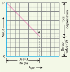
(ii) Diminishing value method.
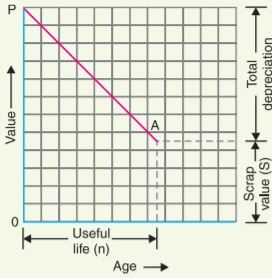
In this method, depreciation charge is made every year at a fixed rate on the diminished value of the equipment. In other words, depreciation charge is first applied to the initial cost of equipment and then to its diminished value. As an example, suppose the initial cost of equipment is Rs 10,000 and its scrap value after the useful life is zero.
If the annual rate of depreciation is 10%, then depreciation charge for the first year will be 0·1 × 10,000 = Rs 1,000. The value of the equipment is diminished by Rs 1,000 and becomes Rs 9,000.
For the second year, the depreciation charge will be made on the diminished value (i.e. Rs 9,000) and becomes 0·1 × 9,000 = Rs 900.
The value of the equipment now becomes 9000 − 900 = Rs 8100.
For the third year, the depreciation charge will be 0·1 × 8100 = Rs 810 and so on.
Mathematical treatment
Let P = Capital cost of equipment
n = Useful life of equipment in years
S = Scrap value after useful life
Suppose the annual unit* depreciation is x.
It is desired to find the value of x in terms of P, n and S.
Value of equipment after one year = P − Px = P (1 − x)
Value of equipment after 2 years = Diminished value − Annual depreciation
= [P − Px] − [(P − Px)x]
= P − Px − Px + Px2
= P(x 2 − 2x + 1) = P(1 − x) 2
∴ Value of equipment after n years = P(1 − x) n
But the value of equipment after n years (i.e., useful life) is equal to the scrap value S.
∴ S = P(1 − x) n or (1 − x) n
= S/P or 1 − x = (S/P) 1/n or x = 1 − (S/P) 1/n ...(i)
From exp. (i), the annual depreciation can be easily found. Thus depreciation to be made for the first year is given by :
Depreciation for the first year = xP = P[1 − (S/P) 1/n ] Similarly, annual depreciation charge for the subsequent years can be calculated.
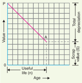
(iii) Sinking fund method.
In this method, a fixed depreciation charge is made every year and interest compounded on it annually. The constant depreciation charge is such that total of annual instalments plus the interest accumulations equal to the cost of replacement of equipment after its useful life.
Let P = Initial value of equipment
n = Useful life of equipment in years
S = Scrap value after useful life
r = Annual rate of interest expressed as a decimal
Cost of replacement = P − S
Let us suppose that an amount of q is set aside as depreciation charge every year and interest compounded on it so that an amount of P− S is available after n years. An amount q at annual interest rate of r will become *q(1 + r) n at the end of n years. Now, the amount q deposited at the end of first year will earn compound interest for n − 1 years and shall become q(1 + r) n − 1 i.e.,
Amount q deposited at the end of first year becomes = q (1 + r) n − 1
Amount q deposited at the end of 2nd year becomes = q (1 + r) n − 2
Amount q deposited at the end of 3rd year becomes = q (1 + r) n − 3
Similarly amount q deposited at the end of n − 1 year becomes = q (1 + r) n − (n − 1) = q (1 + r)
∴ Total fund after n years = q (1 + r) n − 1 + q (1 + r) n − 2 + .... + q (1 + r)
= q [(1 + r) n − 1 + (1 + r) n − 2 + .... + (1 + r)]
This is a G.P. series and its sum is given by :
Total fund = q 
This total fund must be equal to the cost of replacement of equipment i.e., P − S.
∴P − S = q
or Sinking fund, q = (P – S)  .....(i)
The value of q gives the uniform annual depreciation charge.
The parenthetical term in eq. (i) is frequently referred to as the “sinking fund factor”.
∴ Sinking fund factor =
Though this method does not find very frequent application in practical depreciation accounting, it is the fundamental method in making economy studies.
Numericals:
Solution:
Initial cost of transformer, P = Rs 90,000
Useful life, n = 20 years
Salvage value, S = Rs 10,000
Using straight line method,
Annual depreciation charge =  = (90000-10000)/20 = Rs. 4000.
2. A distribution transformer costs Rs 2,00,000 and has a useful life of 20 years. If the salvage value is Rs 10,000 and rate of annual compound interest is 8%, calculate the amount to be saved annually for replacement of the transformer after the end of 20 years by sinking fund method.
Solution:
Initial cost of transformer, P = Rs 2,00,000
Salvage value of transformer, S = Rs 10,000
Useful life, n = 20 years
Annual interest rate, r = 8% = 0·08
Annual payment for sinking fund,
q = (P – S) 
q = ( 200000- 10000)
q = Rs. 4153.
POWER STATION | LOCATION | SPACE | EFFICIENCY | SOURCE LIMITATION |
STEAM | Where there is Enough supply of water and coal. | Needs sufficient space for all equipment. | This is plant is ≈ 25% efficient.
| Has most Limited fuel Reserves. |
HYDRO | Where large reservoirs can be obtained by dam construction. | Needs very large space for constructing a dam | This is plant is ≈ 85% efficient.
| Has undependable water source due to weather variations. |
DIESEL | Where there is required space & water, thus can be located anywhere. | Needs very little space for all equipment | This is plant is ≈ 35% efficient.
| Has Limited fuel Reserves.
|
NUCLEAR | Where there is enough supply of water, but must not be too far away from populated areas. | Needs the least space, compared any other power station of equal capacity | This is plant is ≈ 55% efficient.
| Has sufficient fuel Reserves. |
POWER STATION | GENERATION EQUIPMENT |
STEAM | Are lower than those of Hydro & Nuclear. |
HYDRO | Are very high because of dam construction. |
DIESEL | Lowest compared to all other power stations. |
NUCLEAR | Highest due to complex nuclear reactors. |
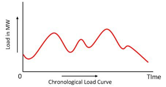
Load curve or chronological curve is the graphical representation of load (in kW or MW) in proper time sequence and the time in hours. It shows the variation of load on the power station. When the load curve is plotted for 24 hours a day, then it is called daily load curve. If the one year is considered then, it is called annual load curve.
The load curve of the power system is not same all the day. It differs from day to day and season to season. The load curve is mainly classified into two types, i.e., the summer load curve and the winter load curve.
The following are the information obtained from load curves.
The performance of a power plant can be expressed through some common performance factors:
Heat Rate (Energy Efficiency)
Overall thermal performance or energy efficiency for a power plant for a period can be defined as
φhr = H / E (1)
where
φhr = heat rate (Btu/kWh, kJ/kWh)
H = heat supplied to the power plant for a period (Btu, kJ)
E = energy output from the power plant in the period (kWh)
Thermal Efficiency
Thermal efficiency of a power plant can be expressed as
μte = (100) (3412.75 Btu/kWh) / φ (2)
where
μte = thermal efficiency (%)
Capacity Factor
The capacity factor for a power plant is the ratio between average load and rated load for a period of time and can be expressed as
μcf = (100) Pal / Prl (3)
where
μcf = capacity factor (%)
Pal = average load for the power plant for a period (kW)
Prl = rated capacity for the power plant (kW)
Load Factor
Load factor for a power plant is the ratio between average load and peak load and can be expressed as
μlf = (100) Pal / Ppl (4)
where
μlf = load factor (%)
Ppl = peak load for the power plant in the period (kW)
Economic Efficiency
Economic efficiency is the ratio between production costs, including fuel, labor, materials and services, and energy output from the power plant for a period of time. Economic efficiency can be expressed as
φee = C / E (5)
where
φee = economic efficiency (cents/kW, euro/kW, ...)
C = production costs for a period (cents, euro, ..)
E = energy output from the power plant in the period (kWh)
Operational Efficiency
Operational efficiency is the ratio of the total electricity produced by the plant during a period of time compared to the total potential electricity that could have been produced if the plant operated at 100 percent in the period.
Operational efficiency can be expressed as
μoe = (100) E / E100% (6)
where
μeo = operational efficiency (%)
E = energy output from the power plant in the period (kWh)
E100% = potential energy output from the power plant operated at 100% in the period (kWh)
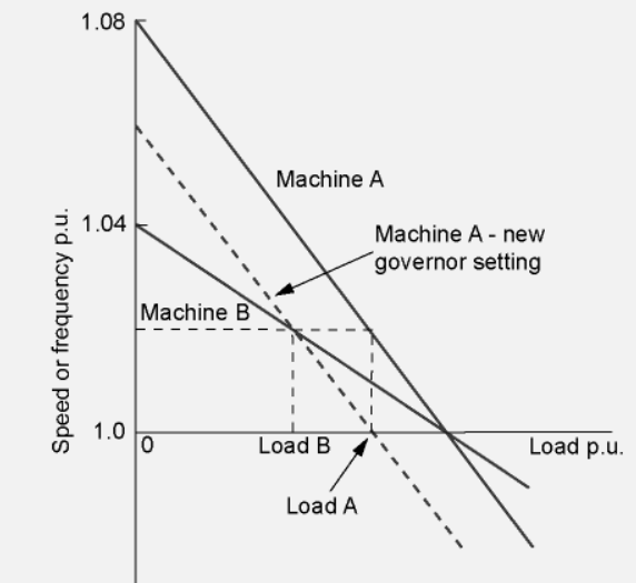
The use of the speed changer enables the steam input and electrical power output at a given frequency to be changed as required. The effect of this on two machines can be seen in Figure 4.8. The output of each machine is not therefore determined by the governor characteristics but can be varied by the operating personnel to meet economic and other considerations. The governor characteristics only completely decide the outputs of the machines when a sudden change in load occurs or when machines are allowed to vary their outputs according to speed within a prescribed range in order to keep the frequency constant. This latter mode of operation is known as free-governor action.
It has been shown that when d is small the voltage difference between the two ends of an interconnector of total impedance R + jX is given by

Also the angle between the voltage phasors (that is, the transmission angle) d is given by

where

When X ^ R, that is for most transmission networks, 
Hence, (1) the flow of power between two nodes is determined largely by the transmission angle; (2) the flow of reactive power is determined by the scalar voltage difference between the two nodes.
These two facts are of fundamental importance to the understanding of the operation of power systems.
Connected Load
It is defined as “the total sum of all the loads (ON and OFF) connected to the power system.
All the loads may not be switched ON together, but such loads have to be calculated to determine the required power and hence the capacity of the units.
For example, if one of the consumers has three lamps of 200 W each, four lamps of 100 W each and a machine consuming 5 kW, then the connected load of the consumer = 3(200) + 4(100) + 5000 = 6000 W
Average Load
As the name implies, it indicates the average value of all the loads occurring on the station for a given time period (such as day/s or month/s or year/s)
It can be expressed as
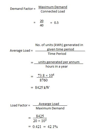
Average load = No. of units (kWh) generated in given time period/time period
Maximum Demand
It is defined as “the maximum value of load that occurs on the system during a specific time period.”
In the figure no. 1, the maximum demand is 40 MW and it occurs around 8 pm. Maximum demand is measured by a max demand meter.
Knowledge of max demand is necessary because the installed capacity of the plant is decided on the basis of max demand since the power station must be capable of supplying the max demand.
Factors Related to Variable Loading Demand Factor
It is defined as “the ratio of maximum demand to the connected load of the system.”
Demand factor = Maximum demand/Connected load
Since, all the connected loads are not ON all the time, Maximum demand < Connected Load.
Hence, Demand factor < 1
It is necessary for determination of the required plant equipment capacity.
Load Factor
It is defined as “the ratio of average load to the maximum demand in a given time period.”
Load factor = Average load/ Maximum demand
It can be daily/monthly/yearly load factor according to the time period considered. It is less than unity because Average load < Maximum demand.
Diversity factor
A power station supplies a variety of consumers. Each consumer will have an individual maximum demand and such max demands may not occur all at the same time.
Diversity Factor is defined as “the ratio of the sum of the individual maximum demands to the total maximum demand on the system. It can be expressed as,
Diversity factor =Sum of individual maximum demands/ Maximum demand of the power station
Numerical:
A plant has a connected load of 40 MW and a maximum demand of 20 MW. 73.8 × 10⁶ kWh energy is generated in a year. Calculate: [i] demand factor, [ii] average load, [iii] load factor.
Solution:
Given data:
References
1. E.I.Wakil, Power Plant Engineering‖, McGraw Hill Publications New Delhi
2. P.K.Nag, Power Plant Engineering‖, McGraw Hill Publications New Delhi.
3. R.Yadav , Steam and Gas Turbines‖ ,Central Publishing House, Allahabad.
4. G.D.Rai, Non-Conventional Energy Sources, Khanna Publishers,Delhi
5. S.P.Sukhatme, Solar Energy‖ Tata McGraw-Hill Publications, New Delhi
6. G R Nagpal Power Plant Engineering , Khanna Publication