UNIT 1
DESIGN OF MACHINE TOOL GEAR BOX
A gearbox is a mechanical device utilized to increase the output torque or change the speed (RPM) of a motor. Its basic requirement is to
Stepped regulation: it is the regulation of speed with discrete values of spindle speeds obtained on machine tools.
Various laws are proposed to obtain the discrete speeds, those are
Geometric Progression
In this progression, the ratio of any two successive spindles is constant.
Φ = geometric progression ratio
n1,n2,n3,……,nz = spindle speed in rpm
z = total number of spindle speed steps
R = range ratio of spindle speeds


n1 = nmin
n2 = n1ϕ = nminϕ
n3 = n2ϕ = n1.ϕ.ϕ = n1.ϕ2 = nminϕ2
n4 = n3ϕ = n1.ϕ3 = nminϕ3
.
.
.
nz = nz-1.ϕ = n1ϕz-1 = nmin.ϕz-1
Arithmetic Progression
In this progression, the difference between any two successive spindles is constant


n1 = nmin
n2 = n1 + d = nmin + d
n3 = n2 + d = nmin + 2d
.
.
nz = nz-1 + d = nmin (z-1)d
In this progression the difference between reciprocal of any two successive spindle speeds is constant.


.
.

Out of these three laws geometric progression law has more advantages due to the following reasons
The steps involved are


Based on available input values of the diameters and maximum diameters of workpiece to be minimum machined corresponding to maximum and minimum cutting speeds.
Range ratio is the ratio of maximum spindle speed to minimum spindle speed


Range ratio R = ϕz-1
Taking log on both sides
(z-1) log10ϕ = log10 R
(Z-1)=  +1
+1


This equation is used to find z and is rounded off to the nearest integer
Normally selected values of z are 2,3,4,6,9,12,16,18,24,17,32 & 36
As n1, n2,…..,nz-1,nz
Z = S1 S2 S3--------SN
S1 – No of stepped steps in stage 1
S2 - No of stepped steps in stage 2
S3 – No of stepped steps in stage 3
Sn – No of stepped steps in Nth stage
Based on the assumptions that, for minimum number of gears to require speed steps ‘z’ is essential to have all stages with same number of speed steps
s1 = s2 = ------= sN = s
Where S is number of speed steps per stage
Z = S. S. S……S(N times)
Z = sN
log10 Z = N log10 S

s could be either 2 or3
for non-integer number‘s’
z = 2N1.3N2
N1 – number of stages with two speed steps
N2 – number of stages with three speed steps
N = N1 +N2
Structural formulae: It is an element of kinematic diagram and is defines as the mathematical expression giving the distribution if number of speed steps in each stage and the number of spindle speed by which two adjacent speed values of each stages are separated
z = s1(x1) s2(x2) s3(x3)……..sN(xN)
Draw the corresponding Diagrams
After drawing all the structural diagrams, a single optimum structure diagram is selected satisfying important conditions as

Motor speed is required to decide
if ni/p = nm (then the shaft are to be coupled directly)
if ni/p ≠ nm (then the shaft are to be connected by belt drive or gear box)
Structural formula
it is the mathematical expression giving the distribution of number of speed steps in each stage and the number of spindle speed steps by which two adjacent speed values of each stage are separated
n = various spindle speed
z = Total number of speed
s = Number of speed steps
N = Number of stages in gear box
x1,x2,…xN = Number of speed steps by which two adjacent speed values of particular stage are separated for first stage, second stage,…,nth stage
Total number of spindle speed steps are
z = s1 . s2 ……sN
x = 1(for difference between adjacent speed values equal to one spindle speed steps)
x = 2(for difference between adjacent speed values equal to two spindle speed steps)
z = s1(x1) . s2(x2)…….sN(xN)
x values
x = 1 (Stage 1)
x2 = s1 (stage 2)
x3 = s1 . s2 (stage 4)
.
.
xN = s1 . s2 . s3 ….. sN-1 (stage N)
Structure Diagram
The diagram describing kinematic structure of the gear box based on a particular structural formula s called as structure diagram
Steps in constructing structure diagram:
Draw (N + 1) vertical lines, each line represents a shaft with first line as input shaft and last line as output shaft.
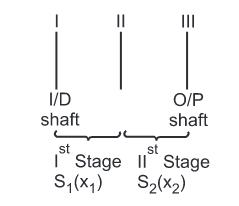
Construct z number of horizontal lines at a spacing of (log10ϕ), each line representing spindle speed
__________
__________
__________
__________
Plot lines on s1 . s2 ……sN on the vertical lines 2 & 3, at the distance x1 x2 …xN respectively using structure formula
z = s1(x1) . s2(x2)…….sN(xN)
Construct transmission line giving distribution from input to output shaft

As 
n2 = n1 . ϕ
Taking log on both sides
log10n2 = log10n1 + log10ϕ
In general
log10np = log10n(p-1) + log10ϕ
Thus structure diagrams shows number of shafts in a gear box, number of gears on each shaft, order of changing transmission in a group and transmission range of individual group.
Types of structure diagram
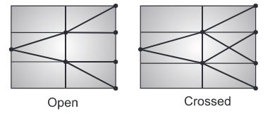
The basic rules to be followed while designing the gear boxes are as follows
¼ ≤ i ≤ 2
In other words
imin =  ≥ ¼ and
imax =  ≤ 2
≤ 2

 ≤ 8
≤ 8
Nmax ≥ Ninput ≥ Nmin
The kinematic arrangement of a multi – speed gear box is shown in figure.
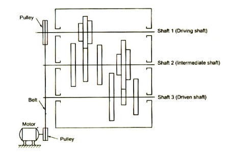
From the figure, it is clear that the kinematic layout shows the arrangement of gears in a
gear box. The kinematic layout provides the following information’s required for gear box design.
The ray diagram is graphical representation of the drive arrangement in general from. In
other words, the ray diagram is a graphical representation of the structural formula, as shown
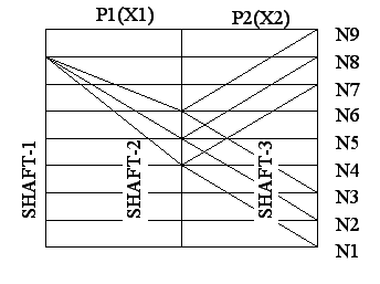
It provides the following data on the drive:
Procedure
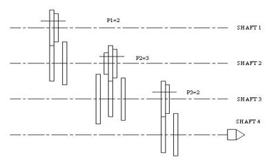
Draw kinematic arrangement for 12 speed gear box
Case.1 | z = 2 (1) . 2 (2) . 3(4) |
|
| |
Calculation of No. of shaft to draw kinetic arrangement: |
| |||
| No. of shafts = No. stages + 1 |
| ||
|
| =3+1=4 |
|
|
Calculation of No. of gears to draw kinematic arrangement: |
| |||
| Shaft 1 | = p1 gears | shaft 1 | = 2 gears |
| Shaft 2 | = p1+ p2 gears | shaft 2 = 2 + 2 | = 4 gears |
| Shaft 3 | = p2 + p3 gears | shaft 3 = 2 + 3 | = 5 gears |
|
| . |
| . |
|
| . |
| . |
|
| . |
| . |
| Shaft n = pn | shaft4 | = 3 gears | |
|
| Total No. of gear | = 14 gears | |
|
|
|
| |

Case.2 | z = 2 (1) . 3 (2) . 2(6) |
|
| |
Calculation of No. of shaft to draw kinetic arrangement: |
| |||
| No. of shafts = No. stages + 1 |
| ||
|
| =3+1=4 |
|
|
Calculation of No. of gears to draw kinematic arrangement: |
| |||
| Shaft 1 | = p1 gears | shaft 1 | = 2 gears |
| Shaft 2 | = p1+ p2 gears | shaft 2 = 2 + 3 | = 5 gears |
| Shaft 3 | = p2 + p3 gears | shaft 3 = 3 + 2 | = 5 gears |
|
| . |
| . |
|
| . |
| . |
|
| . |
| . |
| Shaft n = pn | shaft4 | = 2 gears | |
|
| Total No. of gear | = 14 gears | |
|
|
|
| |
Case.3 | z = 3 (1) . 2 (3) . 2(6) |
Calculation of No. of shaft to draw kinetic arrangement:
No. of shafts = No. stages + 1
=3+1=4
Calculation of No. of gears to draw kinematic arrangement:
Shaft 1 | = p1 | gears | shaft 1 | = 3 gears |
Shaft 2 | = p1+ p2 gears | shaft 2 = 3 + 2 = 5 gears | ||
Shaft 3 | = p2 | + p3 gears | shaft 3 = 2 + 2 = 4 gears | |
|
| . |
| . |
|
| . |
| . |
|
| . |
| . |
Shaft n = pn |
| shaft4 | = 2 gears | |
|
| Total No. of gear | = 14 gears | |

A gear box is to be designed to provide 12 output speeds ranging from 160 to 2000 r.p.m. The input speed of motor is 1600 r.p.m. Choosing a standard speed ratio, construct the speed diagram and the kinematic arrangement.
Given data: n = 12; Nmin = 160 r.p.m.; Nmax = 2000 r.p.m.; Ninput = 1600 r.p.m.
To find: Construction of the speed diagram and the kinematic arrangement.
Solution:
Selection of spindle speeds:
We know that  = ϕn-1
or  = ϕ12-1 or ϕ = 1.254
We can write, 1.12 x 1.12 = 1.254 …
So =1.12 satisfies the requirement. Therefore the spindle speeds from R 20 series, skipping one speed, are given by
160, 200, 250, 315, 400, 500, 630, 800, 1000, 1250, 1600 and 2000 r.p.m.
Structural formula: For 12 speeds, the preferred structural formula
=3(1) 2(3) 2(6)
1st stage 2nd stage 3rd stage
Speed diagram (or Ray diagram):
Procedure:
Stage 3  and
and

Stage 2 
 and
and

Stage 1 
 and
and

Ratio requirements are satisfied.
Kinematic arrangement: The kinematic arrangement for 12 speed gear box is drawn, as shown in figure.

Reference books: