Back to Study material
MSD

UNIT 3

 DESIGN OF BELT CONVEYOR SYSTEM FOR MATERIAL HANDLING


The development of material handling system to move materials from one stage to another stage is very important. Materials handling includes moving, packaging and storing all the materials used by the production unit. Material handling is one of the important management and also in production.

Materials are received and is moved into the plant and transferred to the storeroom. When materials are needed it is moved along the path of manufacturing. Plant layout and, material handling are closely inter-related; it has to be adjusted according to the layout of the plant.


A general definition of the system is a complex unity formed of many diverse parts subjected to a common purpose.

The characteristics of system are called subsystems.

Material handling can also be considered to be a system whose subsystem is

  • Method or design to be adopted
  • Maintenance required for the equipment
  • Transportation made by the suppliers, distributors etc...
  • Types of material handling equipment to be used.
  • The system concept of material handling means the different types of material handling needed at different parts of an industry. The use of this will reduce overall cost.

  • It should operate at low initial cost and operating cost
  • The system should not create problem to the product cycle
  • Future development should be easy
  • The system should be selected so that it should achieve maximus output.
  •  


    The basic objectives of material handling system are:

  • Reduce the manufacturing cycle time
  • Transport of loads in planned quantity
  • Safe transport of the load without damages
  • Contribute toward a better control of the flow of goods
  • Gain higher productivity at lower manufacturing cost
  • Safe operation
  • Achieve decreased storage requirement
  •  


    The types of load handled by a material handling system can be of two types

          Bulk load

  • A bulk load is the form of particles, powders or lumps of homogeneous materials, which cannot be counted by numbers.
  • Example are coal, iron ore, sand, cement, clay etc...
  •  

          Unit load

    Unit loads are those loads which can be counted by numbers or units

    Examples are machine, building block, containers etc...
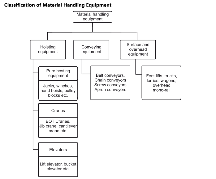
  • Containerization
  • In a high productivity cycle, handling small sized packets or units is inconvenient and uneconomical.
  • In such cases, containers of different sizes and shapes are used for handling such materials. Many a time, certain quantities of bulk material can be placed in a container which can then be handled as unit load. This process of converting a bulk load into a unit load is called as containerization.
  •  


  • Limit the number of containers sizes and shapes
  • Design the container based on the requirements of the material to handle
  • Container size taking into account the area or space available of handling material.
  • Containers design for stacking arrangement. This reduces storage costs.
  • The containers should be properly coated or painted
  • Colour code for the containers by functions.
  • Wooden or plastic containers are rust free, but have limitations on their life, cleanliness and can also be hazardous in case of fires
  • Steel containers are sturdy and have a long life
  • Wire mesh and steel containers are preferred over wooden or plastic containers.

  • In this conveyor, the active side of belt remains flat supported by cylindrical rollers or flat slider bed
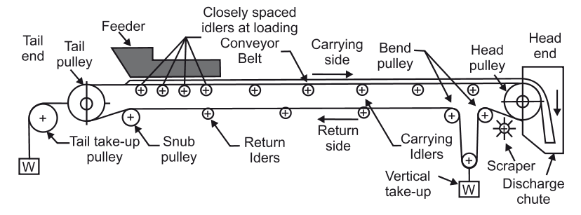
  • A belt conveyor consist of two end pulleys, with a continuous loop of material that rotates about them
  • The pulleys are powered, moving the belt and the material on the belt forward. The belt span is supported by idlers spaced along the length
  • Flat belts are conveniently used for conveying parts between workstation or in assembly line in mass production of goods.

  • In this type of conveyor the side belts remain flat supported by cylindrical rollers. These are used for shorter length and suitable for unit loads such as boxes, packages etc. and in manufacturing, assembly operation. These are used for conveyors between workstation and in assembly line for mass production.


    In this conveyor wide flat belt is supported on troughed carrying rollers or shaped supporting surface so that the two edges of the active side of the belt are elevated from the middle part to form a trough, it provides a greater carrying capacity than a flat belt of equal width for conveying bulk materials. Such type of conveyors are used in handling bulk material of different classes.


    Capacity of belt conveyor (Q):

    The material which is carried out by conveyor system is called capacity of the conveyor.

        Q = C x b2 x V m3/sec

     where,  b = Storage material width in m = (0.9 B – 0.05)

        B = Width of the belt in m

        Q = Capacity of conveyor  m3/sec

        M = Mass capacity of conveyor

        V = Speed of belt

    Horizontal belt conveyor capacity :


        Q = C x b2 x V

        Q = C(0.92B – 0.05)2 V m3/sec

     where    C = Surge factor
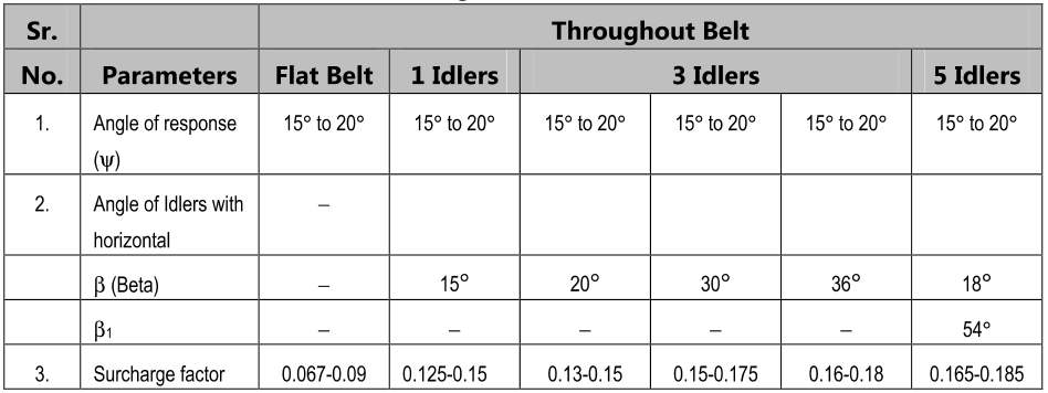
    Capacity of inclined Belt Conveyors :

         Q = K x b2 x V m3/sec

         Q = K (0.9B – 0.05)2 V m3/sec

         Q = K (0.9B – 0.05)2 V x 3600mi3/sec

     Mass capacity of inclined conveyor

         M = ρQ

         K = Flow ability Factor

         ρ = Density of material 

    Conveyor belt speed :

    The running conveyor belt travels at speed which is called as conveyor speed

    The speed depend on

  • The size of lump
  • The belt width
  • Type of material
  • The weight of material is fine and light in order to prevent slippage

    The wider belts are operated at higher speeds
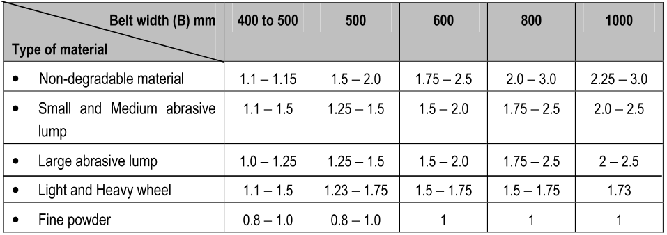
  • The different conveyor belts speed for different material is given in the table below
  • Standard belt width used for the conveyor belts are:

    400, 450, 500, 600, 750, 800, 900, 1000, 1200, 1400, 1600, 1800, 2000, 2200, 2400 mm.


    Synthetic rubber is in use for belts. Combination of synthetic and natural rubber have been found satisfactory. Synthetics are superior under special circumstances eg, neoprene for flame resistance and resistant to petroleum based oils, Buna N for resistance to vegetable, animal and petroleum oils, and butyl for resistance to heat.

    Fabric Ply Belts :

    The most common carcass design is made up of layers or piles of woven fabrics bonded together. The fabric is made from a variety of materials. Some of these are listed below with characteristics.

    Material

    Characteristics

    Cotton(Natural Cellulose Composition)

    This is the only natural fibre carcass used excessively in conveyor belts. Its strength increases when it is wet but the absorption of moisture results in poor dimensional stability. It is also susceptible to mild dew attacks.

    Rayon (Regenerated Cellulose Composition)

    Slightly stronger that cotton, but tensile strength is lowered by water. High absorption reduces the dimensional stability. Chemical resistance is similar to cotton and is Susceptible to mildew attack.

    Glass

    Very high strength compared to rayon. Low elongation, mainly used in high temperature applications. It has poor flex life and has a limited use.

    Nylon (Polyamide)

    High strength, high elongation, good resistance to abrasion, fatigue and impact. Moisture absorption not as high as cotton but it reduces the dimensional stability.

    Polyester

    High strength, exceptionally good abrasion and fatigue resistance. Extremely low moisture absorption and is unaffected by mildew and is used extensively for conveyor belts (70 to 75% of all conveyor)

    Kevlar (Aramid)

    Aramid has twice the strength of steel, with stretch characteristics roughly half wave between steel and polyester. It is significantly lower in weight that steel and will not rust. The belts made from this are extremely expensive and are used only in special circumstances.


    The conveyor arrangement uses the following types of pulleys

  • Driving Pulley (Head and Tail pulley)
  • Snub Pulley
  • Idlers
  • Driving pulley (Head and Tail pulley)

  • Drive pulley is located at the discharge terminal of the conveyor. It provides driving force for the conveyor. In order to increase pulley life and traction, it often has larger diameter than other pulleys.
  • They are manufactured in a wide range of size and consist of a continuous rim and two end discs fitted in the hub. The rim is supported by stiffening discs welded to it to support large loads.
  • The pulley may be straight faced or crowned due to such arrangements the crown helps in keeping the belt cantered
  • Crown height is 0.5% of pulley width and not less than 4 mm.
  • Snub Pulley

    These are used to increase the angle of wrap of the belt and overall for all the necessary changes in belt direction in the areas of counterweight tensioner, mobile unloader etc.

    The choice of the optimum conveyor system and its project design and rationalization depends on full knowledge of the construction characteristics and the forces involved that apply themselves to all the system components.
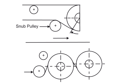
    16) BELT TAKE UP ARRANGEMENT

      Idlers

    Idlers


    The efficiency of belt conveyor is mainly dependent on idlers. For higher efficiency of conveying systems, the idlers must be accurately made and provide a rigid framework. This will maintain a permanent, well balanced smooth running alignment.


    There are, in general, three kinds of belt carrying idlers used in handling of bulk materials. The type of idlers affects the cross-sectional load on the belt.

  • Flat belt idlers: are used for granular materials having an angle of repose of not less than 35°. Flat belt idlers are preferred for low capacity requirements.
  • Toughing idlers with 20° through: are used for conveying all kinds of bulk materials.
  • Troughing idlers  with  35°  and 45°  through: are  used  for  transportation of  small particles  and lightweight materials like grain, cotton seed etc.
  •  


    There are two basic types of belt conveyor idlers:


          Carrying idlers which support the loaded run of the conveyor belt; and

          Return idlers which support empty return run of the conveyor belt.


    Carrying Idlers


      Carrying idlers
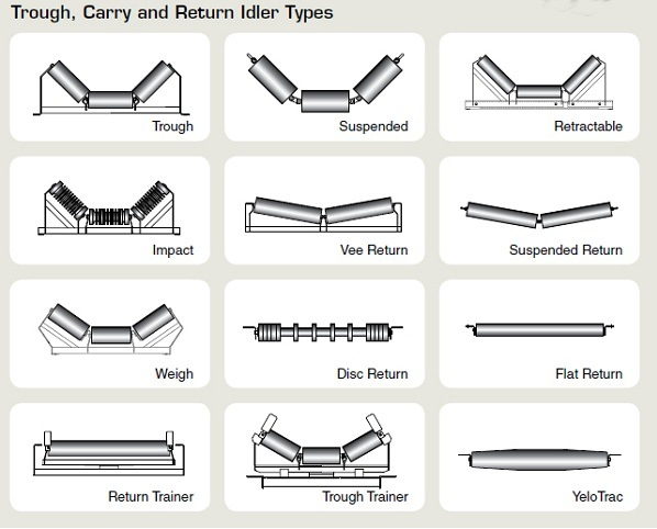
  • Usually troughed with 3 equal size rollers on a frame in mining applications
  • Some suspended catenary systems have 5 rollers
  • Toughing angles are usually 20, 35, 45 degrees
  • Deeper trough more volume
  • Requires thinner belt to lay in trough which limits strength.
  •     Return Idlers


  • Usually Flat and one piece
  • Sometimes two-piece V for belt training
  • Spiral roll to self and belt clean
  • Rollers


    Main functions of take up are:

  • Ensuring adequate tension of the belt leaving the drive pulley so as to avoid any slipping of the belt.
  • Permanently ensuring adequate belt tension at  the loading point and at any other point of the  conveyor to keep the troughed belt in shape  and limit belt sag between carrying idler
  • Compensating    for    operating    belt    length    variation  due  to  physical  factors  (instantaneous tensions,    permanent  elongation,    outside    temperature,  temperature  of  conveyed  material, dampness, etc.)
  • Making available, if needed, an adequate extra length of belt to enable re-joining without having to add an extra piece of belt.
  •  

    Two types of belt take up devices are generally used:


          Fixed take-up devices that are adjusted periodically

          Automatic take-up devices (constant load type)


    Fixed take-up devices that are adjusted periodically

    In this type of take-up devices, the take-up pulley remains fixed between successive periodic adjustments.


    Take-ups of this type generally used are:


  • Screw take-up  — in this system the adjustment is manually effected by means of two  screws acting  upon  the  pulley  bearings  and  which  are  tightened  simultaneously  or  successively.  The screw  is  normally  of  non-extendable  type  and  sliding  surfaces  are  suitably  protected  against ingress of dirt. In this system, the applied tension is not fully determinable. This generally leads to excessive tension of belt (when tension is insufficient, belt slips and quickly deteriorates). This excessive tension is unavoidable and shall be taken into account when determining the size of the belt, designing the mechanical components and calculating the adjustments.  For  this  reason, these devices are used only in case of short conveyors of up to 60 m length s and under light duty cycle condition
  •  

  • Winch take-up — in this system, the tension is adjusted by means of a mechanical motorized device which does not automatically compensate for belt length variations. A tension indicator may be included between winch and pulley. This system also requires careful checking of tension and leads to excessive belt tension in order to avoid too frequent take-ups. However, it may be used  for  long  conveyors  and under  heavy  duty  conditions  provided  that  these  conveyors  are equipped with belts having very low elongation coefficient under the effect of load and over a long period, for example, steel cord belt s which are use d almost exclusively.
  •  

          Automatic take-up devices


    In this system, take-up pulley is mounted on slides or on a trolley and travels freely while a constant tension is automatically maintained to ensure normal conveyor operation in all cases. The most frequently used type is gravity weight operated take-up device. Hydraulic, pneumatic or electrical take-up devices of

    Various types are also used. All types of automatic take up devices shall include a system for adjusting belt tension. Automatic take-up has following features:


  • It is self-adjusting and automatic.
  • Greater take-up movement is possible.
  • It is suitable for horizontal or vertical installation.
  • It is preferred for long center conveyors.
  • It can be located at drive end (preferred for low tensions).
  • In case of underground mines, provision of loop at drive end may be made to cater for take-up and small extension of belt conveyor lengths.
  •  


    The power requirement of belt conveyor is

  • Power required to lift the load at height ‘h’
  • Power required to overcome frictional resistance at different points
  •  

    Let,   Q = Conveyor capacity m3/sec

         ρ = Mass density of material kg/ m3

         h = Natural trough which is to be lifted ‘h’ m

          L = Length of belt m

        Co = Specific factor
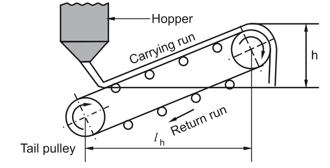
     

  • Power required to lift the load at height ‘h’
  •  

  • Power required to overcome frictional resistance at different points
  •  


    Total power required (P)

    P = +


    Determine the resistance offered by a single carrying and return idler for the conveyer having the following data

    Capacity of the conveyer = 400tph

    Belt speed = 2m/sec

    Mass of belt = 16kg/m

    Mass of idler = 25.1 kg

    Carrying side pitch = 2 m

    Return side pitch = 2 m

    Coefficient of friction between the idler and the pulley = 0.02

    Coefficient of friction between the roller pin and idler = 0.5

    Belt Inclination = 15o


    Index
    Notes
    Highlighted
    Underlined
    :
    Browse by Topics
    :
    Notes
    Highlighted
    Underlined