UNIT 4
DESIGN OF CYLINDERS AND PRESSURE VESSSELS
Cylindrical pressure vessels are classified into two groups
A cylinder is considered to be thin when the ratio of its wall thickness to the internal radius is less than 1/10. In thin cylinder the stress distribution is assumed to be uniform over the thickness of the wall.
If the ratio of thickness to internal radius of cylinder is more than 1/10, the cylinder is knows as thick cylinder. In thick cylinder hoop stress distribution over the thickness of wall is not uniform. It is maximus at the inner circumference and minimum at the outer circumference.
A cylinder is considered to be thin when the ratio of its wall thickness to the internal radius is less than 1/10. Boiler shells, pipes, tubes, and storage tanks are treated as thin cylinders.
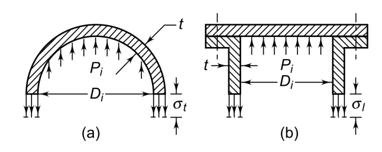
There are two principal stresses in thin cylinder—the circumferential or tangential stress (st) and longitudinal stress (s1). It is assumed that the stresses are uniformly distributed over the wall thickness. Considering equilibrium of forces acting on the half portion of cylinder of unit length
DiPi = 2σtt
 (1)
(1)
where,
Pi = internal pressure (N/mm2)
Di = internal diameter of cylinder (mm)
t = cylinder wall thickness (mm)
Considering equilibrium of forces in the longitudinal direction

 (2)
(2)
From Eq’s 1 and 2, it is seen that the circumferential stress (st) is twice the longitudinal stress (s1). Therefore, we have the following criteria:
(i) When the circumferential stress exceeds the yield strength, failure will occur lengthwise. Also, when the longitudinal stress exceeds the yield strength, failure will occur in the transverse section. It can be concluded that in case of thin cylinders subjected to internal pressure, the tendency to burst lengthwise is twice as great as at transverse section.
(ii) In case of thin cylinders subjected to internal pressure, the circumferential stress should be the criterion for determining the cylinder wall thickness.
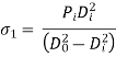
Equation 1 is rewritten as,
 (3)
(3)

A spherical pressure vessel with a thin wall, cut into two halves. Considering equilibrium of forces for each half,


where,
Pi = internal pressure (N/mm2)
Di = internal diameter of cylinder (mm)
t = cylinder wall thickness (mm)
(st) = permissible tensile stress (N/mm2)
The volume V of the shell is given by,


If the ratio of thickness to internal radius of cylinder is more than 1/10, the cylinder is knows as thick cylinder. Hydraulic cylinders, high-pressure pipes and gun barrels are examples of thick cylinders. The difference between the analysis of stresses in thin and thick cylinders is as follows:
In this section, it is assumed that the cylinder is subjected to only internal pressure. Consider an elemental ring of radius r and radial thickness dr. (sr) and (st) are radial and tangential stresses respectively. Considering the equilibrium of vertical forces
2σtdr + 2(r+dr)(σr+dσr) = 2rσr
Neglecting the term (dr x dσr), the above expression is written as
 (a)
(a)

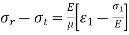
It is further assumed that the axial stress (σ1) is uniformly distributed over the cylinder wall thickness. Therefore, the strain (ε1) is constant.

 (b)
(b)
where E is the modulus of elasticity and (m) is Poisson’s ratio. The right-hand side of Eq. (b) is constant and is denoted by (–2Cl ).
σr - σt =–2Cl (c)
Adding Eqs. (a) and (c),
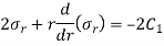
Multiplying both sides of the above equation by (r),
 (d)
(d)
Since,
 (e)
(e)
From (d) and (e),

Integrating with respect to r,
 or,
or,
 =
= (f)
(f)
Substituting the above value in the Eq. (c),
 =
= (g)
(g)
The constants C1 and C2 are evaluated from the following two boundary conditions:
 when
when 
 when
when 


Substituting the constants in Eqs. (f) and (g),

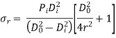
The negative sign is introduced in the expression for (σr) since it denotes compressive stress.
At the inner surface of the cylinder,

and the stresses are given by,
σr = –Pi

At the outer surface of the cylinder,

and the stresses are given by
σr = 0

The variation of principal stresses (σr) and (σt) across the cylinder thickness is shown in above fig
The principal stress in axial direction (s1) is assumed to be uniform over the cylinder wall thickness. Considering equilibrium of forces in the axial direction,

There are a number of equations for the design of thick cylinders. The choice of equation depends upon two parameters—cylinder material (whether brittle or ductile) and condition of cylinder ends (open or closed).
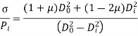
When the material of the cylinder is brittle, such as cast iron or cast steel, Lame’s equation is used to determine the wall thickness. It is based on the maximum principal stress theory of failure, where maximum principal stress is equated to permissible stress for the material. As discussed in the preceding section, the three principal stresses at the inner surface of the cylinder are as follows:
σr = –Pi
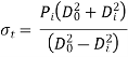

Therefore,
σt ˃ σ1 ˃ σr


or
Substituting (Do = Di + 2t) in the above equation,
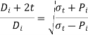


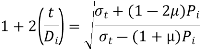
When the material of the cylinder is ductile, such as mild steel or alloy steel, maximum strain theory of failure is used as a criterion to indicate failure. This theory is also called St Venant’s theory. According to this theory, the material begins to yield or begins to fail when the maximum strain at a point equals the yield point strain in a simple tension test. The three principal stresses at the inner surface of the cylinder are as follows:
σr = –Pi (a)
 (b)
(b)
 (c)
(c)
 (d)
(d)
And
 (e)
(e)
From expressions (d) and (e),

σ = σt - µ(σr + σ1)
Substituting the value of principle stress
Rearranging the terms,

Substituting ( in the above equation,

Therefore,
 (Clavarino’s and Bernie’s equation)
Clavarino’s equation is applicable to cylinders with closed ends and made of ductile materials. When the cylinder ends are open,
σ1 = 0
and σ = σ t – µ(σ r + σ 1) = σ t – µ σ r
Birnie’s equation is applicable to open cylinders made of ductile material.
Autofrettage is a process of pre-stressing the cylinder before using it in service. It is used in case of high-pressure cylinders and gun barrels. When the cylinder is subjected to internal pressure, the circumferential stress (st) at the inner surface limits the pressure capacity of the cylinder. In the pre- stressing process, residual compressive stresses are developed at the inner surface. When the cylinder is loaded in service, the residual compressive stresses at the inner surface begin to decrease, become zero and finally become tensile as the pressure is gradually increased. There are three methods of pre- stressing the cylinder. They are as follows:
Compound Cylinders
A compound cylinder, consisting of a cylinder and a jacket is shown in Fig(a). The inner diameter of the jacket is slightly smaller than the outer diameter of the cylinder. When the jacket is heated, it expands sufficiently to move over the cylinder. As the jacket cools, it tends to contract onto the inner cylinder, which induces residual compressive stresses. There is a shrinkage pressure P between the cylinder and the jacket. The pressure P tends to contract the cylinder and expand the jacket as shown in Fig.(b) and (c)
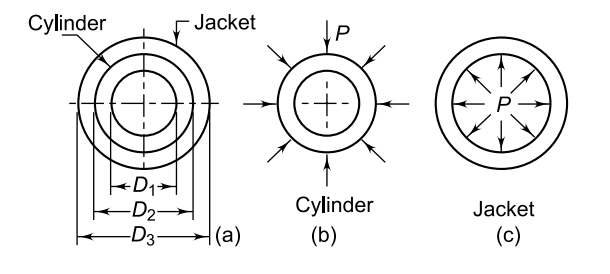

The shrinkage pressure P can be evaluated from the above equation for a given amount of interference (d). The resultant stresses in a compound cylinder are found by superimposing the two stresses—stresses due to shrink fit and those due to internal pressure.
A gasket is a device used to create and maintain a barrier against the transfer of fluid across the mating surfaces of a mechanical assembly. It is used in static joints, such as cylinder block and cylinder head. There are two types of gaskets—metallic and non-metallic. Metallic gaskets consist of sheets of lead, copper or aluminum. Non-metallic gaskets are made of asbestos, cork, rubber or plastics.
A bolted assembly of cylinder, cylinder head and gasket is shown in Fig. Initially, the bolt is tightened by means of a spanner to induce a preload Pl. The stiffness or spring constant k of a machine element is the load required to produce unit deflection. It is given by the ratio of the load to the deflection produced by that load. When machine member is loaded in tension or compression,


The stiffness of bolt is given by

Where,
kb = stiffness of the bolt (N/mm)
d = nominal diameter of the bolt (mm)
l = total thickness of the parts held together by the bolt(mm)
E = modulus of elasticity of bolt material (N/mm2)
There are three members in the grip of the bolt— cylinder cover, cylinder flange and gasket. They act as three compression springs in series. Their combined stiffness ( kc ) is given by,
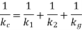
where k1 and k2 are the stiffness of the cylinder cover and the cylinder flange respectively and kg is the stiffness of the gasket. It is difficult to predict the area of flanges compressed by the bolt. It is assumed that a hollow circular area of (3d) and (d) as outer and inner diameters respectively is under the grip of the bolt.


where t is the thickness of the member under compression. When the gasket is very soft relative to the flanges, it is the gasket that is compressed during the tightening of the bolt. In such cases, the flanges are neglected and the stiffness of the gasket is considered to be kc.
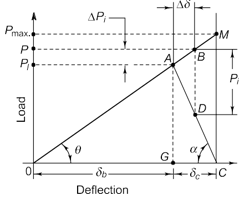
When the bolt is tightened with a preload Pl, the bolt is elongated by an amount (db) and the two flanges with the gasket are compressed by an amount(dc). When the stresses are within the elastic limit,


Line OA represents elongation of the bolt, while line CA indicates the compression of the flanges. The slope of the line CA is negative because it indicates compression.
When the cylinder is assembled and put into service, it is further subjected to an external load P operating inside the vessel. The effect of P is as follows
Since,
 (a)
(a)
 (b)
(b)
Dividing Eqs (c) by (d),

The resultant load on the bolt is given by,
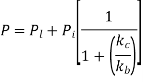
P = P1 + 
The effect of the gasket on the bolted assembly can be explained with the help of the above equations, which can be expressed in the following manner:
When there is no gasket, the flanges are more rigid than the steel bolt, or
kc > kb
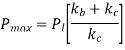
When (kc) is extremely large compared to (kb), the expression within bracket has a limiting value of zero, and
P = Pl
which indicates that almost all of the external load Pi is borne by the flanges to relieve their initial compression. This may lead to leakage between two flanges.
When there is a gasket of elastic material,
kb > kc
When (kb) is too large compared with (kc), the expression within bracket has a limiting value of one, and
P = Pl + Pi
which indicates that a major portion of the external load is borne by the bolt. This is desirable for leak-proof joints. The elongation of the bolt will continue along the line OA as the operating pressure is gradually increased. The limiting point is M, where the compression of flanges becomes zero and the joint is on the verge of opening. The corresponding load (Pmax.) indicates the capacity of the cylinder to bear the load.
∆OAG and ∆OMC are similar triangles. From the geometry of similar triangles,


Substituting Eqs (a) by (b),
An unfired pressure vessel is defined as a vessel or a pipeline for carrying, storing or receiving steam, gases or liquids at pressures above the atmospheric pressure. Such pressure vessels are designed according to national and international codes. The Indian standard code for pressure vessels gives the design procedure for welded pressure vessels that are made of ferrous materials and subjected to internal pressure from 1kgf/cm to 200 kgf/cm2. (1 kgf = 9.81 N). Small pressure vessels with diameters less than 150 mm or water containers with capacities of less than 500 liters do not come under the scope of this code. The code does not include steam boilers, nuclear pressure vessels or hot water storage tanks.
Case1
Welded joint: Double welded butt joint with full penne/ single welded butt joint with backing strips.
Inspection: Fully radiographed
Case2
Welded joint: Double welded butt joint with full penne/ single welded butt joint with backing strips.
Inspection: Spot radiographed
Case3
Inspection: Visual Inspection

The construction of a welded pressure vessel is shown in Fig. There are four categories of welded joints—A, B, C and D. The term category defines only the location of welded joint in the vessel and never implies the type of welded joint.
The welded joints included in four categories are as follows
Pressure vessels are classified into three groups—Class 1, Class 2 and Class 3. Class 1 pressure vessels are used to contain lethal and toxic substances. They include poisonous gases and liquids that are dangerous to human life, e.g., hydrocyanic acid, carbonyl chloride or mustard gas. Liquefied petroleum gas is not classified as a lethal substance. Class 1 pressure vessels are also used when the operating temperature is less than –20°C. There are two types of welded joints used in these vessels—double welded butt joint with full penetration and single welded butt joint with backing strip. Welded joints of Class 1 pressure vessels are fully radiographed.
Class 2 pressure vessels are those which do not come under Class 1 or Class 3 categories. The maximum thickness of the main shell in this case is limited to 38 mm. The types of welded joints in Class 2 pressure vessels are the same as those in Class 1. However, in Class 2 pressure vessels, the welded joints are spot radiographed. Class 3 pressure vessels are used for relatively light duties. They are not recommended for service when the operating temperature is less than 0°C or more than 250°C. The maximum pressure is limited to 17.5 kgf/cm2 (1 kgf = 9.81 N) while the maximum shell thickness is limited to 16 mm. They are usually made from carbon and low alloy steels. Welded joints in Class 3 pressure vessels are not radiographed.
There are three terms related to pressure:
working pressure, design pressure and hydrostatic test pressure.
The maximum working pressure is that which is permitted for the vessel in operation. It is the pressure required for the processes that are carried out inside the pressure vessel. The design pressure(P) is the pressure used in design calculations for such quantities as the shell thickness and also in the design of other attachments like nozzles and openings. The design pressure is obtained by adding a minimum 5% to the maximum working pressure, or
Design pressure = 1.05 (maximum working pressure)
The pressure vessel is finally tested by the hydrostatic test. The hydrostatic test pressure is taken as 1.3 times the design pressure. Therefore,
Hydrostatic test pressure = 1.3 (design pressure) Pressure vessels are fabricated from steel plates welded together by the fusion welding process.
In fusion welding, the weld is made in a state of
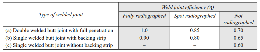
fusion without hammering. It includes arc welding, gas welding, thermite welding and electron beam welding. The term weld joint efficiency is often used in pressure vessel design. It is defined as the ratio of the strength of the welded joint to the strength of the plates. The magnitude of weld joint efficiency( depends upon two factors—the type of weld
and the method of weld inspection. The three types of commonly used welded joints are shown in Fig below. The weld joint efficiency of these joints is given in Table below.

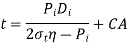
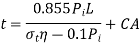
The equations for the thickness of cylindrical or spherical shells are based on the theory of thin cylinders, with suitable modifications. The thickness of a cylindrical shell subjected to internal pressure, is given by,
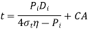
The thickness of the spherical shell is given by
where,
t = minimum thickness of the shell plate (mm)
Pi = design pressure (MPa or N/mm2)
Di = inner diameter of the shell (mm)
st = allowable stress for the plate material (N/mm2)
h = weld joint efficiency
CA = corrosion allowance (mm)

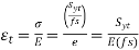
The allowable stresses for the plate material are obtained from the following expressions:


The factor of safety of 1.5 or 3 in the above expressions is used under the following two operating conditions:
For high temperature applications, the values of allowable stresses at design temperature are given in the standard. The values of yield strength (Syt) for commonly used carbon and low alloy steels are given in Table.
The walls of the pressure vessel are subjected to thinning due to corrosion, which reduces the useful life of the vessel. Corrosion in pressure vessels is of the following forms:
Material | Syt (N/mm2) | |
I S 2002–1962 | I | 200 |
| 2A | 205 |
| 2B | 255 |
IS 2041–1962 | 20Mo55 | 275 |
| 20Mn2 | 290 |
IS 1570–1961 | 15Cr90Mo55 | 290 |
| C15Mn75 | 225 |
Provision has to be made by suitable increase in wall thickness to compensate for the thinning due to corrosion. Corrosion Allowance (CA) is the additional metal thickness over and above that is required to withstand the internal pressure. A minimum corrosion allowance of 1.5 mm is recommended unless a protective lining is employed. due to corrosion. Corrosion Allowance (CA) is the additional metal thickness over and above that is required to withstand the internal pressure. A minimum corrosion allowance of 1.5 mm is recommended unless a protective lining is employed.
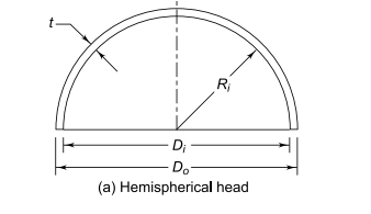
Formed heads are used as end closures for cylindrical pressure vessels. There are two types of end closures—domed heads and conical heads. The domed heads are further classified into three groups—hemispherical, semi-ellipsoidal and torispherical. Hemispherical heads have minimum plate thickness, minimum weight and consequently lowest material cost. However, the amount of forming required to produce the hemispherical shape is more, resulting in increased forming cost. The thickness of the hemispherical head is given by,


It is observed that the thickness of the semi-ellipsoidal head is more (almost twice) than the corresponding hemispherical head, and to that extent, the material cost is more. However, due to the shallow dished shape, the forming cost is reduced.
The length of the straight portion (Sf) is given by,
Sf = 3t or 20 mm (whichever is more)
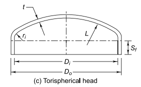
Torispherical heads are extensively used as end closures for a large variety of cylindrical pressure vessels. They are shaped by using two radii—the crown radius L and knuckle radius ri. The crown radius L is the radius of the dish, which constitutes the major portion of the head. The knuckle radius ri is the corner radius joining the spherical crown with the cylindrical shell. Torispherical heads require less forming than semi-ellipsoidal heads. Their main drawback is the local stresses at the two discontinuities, namely, the junction between the crown and the knuckle radius and the junction between the knuckle radius and the cylindrical shell. The localized stresses may lead to failure due to brittle fracture. The thickness of a torispherical head is given by,
where L is the inside crown radius.
The knuckle radius ri is taken as 6% of the crown radius,
or ri = 0.06 L
The crown radius L should not be greater than the outside diameter of the cylindrical shell. Therefore,
L < Do
Hemispherical and semi-ellipsoidal heads are used for tall vertical towers because they are practically free from discontinuities. In such cases, the cost of the top end closure is only a small part of the total cost of the pressure vessel. Also, the space is not a limiting factor for vertical pressure vessels. Torispherical heads are more economical than other types of domed heads. Owing to their compact construction, they are used for horizontal pressure vessels such as tankers for water, milk, petrol, diesel and kerosene. They are also used for small vertical pressure vessels.
Openings are provided in the pressure vessel; these could be an inlet and outlet pipe connections, manhole or hand hole, and connections for pressure gauges, temperature gauges and safety valves. The openings are circular, elliptical or round. The inner diameter of a manhole is generally 380 mm. Such openings are designed by the area compensation method.
The basic principle of the area compensation method is illustrated in Fig. When the opening is cut in the pressure vessel, an area is removed from the shell. It must be reinforced by an equal amount of area near the opening. The area ‘removed’ should be equal to the area ‘added’. The area is added by providing a reinforcing pad in the form of annular circular plate around the opening. It should be noted that in this method, we are considering cross-sectional area in the form of a rectangular strip. It is not the compensation of volume of metal that has been cut due to the opening by means of the reinforcing pad.

It is not always necessary to replace the actually removed area of the metal. The plate of the shell and nozzle are usually thicker than would be required to withstand pressure. This partially compensates for loss of area in the opening. As shown in Fig below

A = d tr
where,
A = area of metal removed in corroded condition (mm2)
d = inner diameter of opening in corroded condition
= (di + 2CA) mm
di = inner diameter (nominal) of nozzle (mm)
tr = required thickness of cylindrical shell (mm)
The required thickness tr is given by

The metal used for reinforcement should be located in the vicinity of the opening. The limiting dimension X parallel to the wall of the cylindrical shell is given by
X =d or  (whichever is maximum)
The limiting dimensions h1 and h2 parallel to the nozzle wall are given by,
h1 or h2 = 2.5 (t – CA)
h1 or h2 = 2.5 (tn – CA) (whichever is minimum)
where,
t = total thickness of the wall of cylindrical shell (mm)
tn = total thickness of nozzle wall (mm)
The area A1 of excess thickness in the vessel wall, which is available for reinforcement, is given by
A1 = (2X – d) (t – tr – CA)
The area A2 of excess thickness in the nozzle wall is given by,
A2 = 2h1 (tn – trn – CA)
where (trn) is the thickness required for the nozzle wall to be able to withstand the pressure,
or 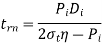
The area A3 of the inside extension of the nozzle is given by,
A3 = 2h2 (tn – 2CA)
The total area available for reinforcement is (A1 + A2 + A3).
When,
(Al + A2 + A3) ≥ A
the opening is adequately reinforced and no reinforcing pad is required. When this condition is not fulfilled, a reinforcing pad of area A4 is required.
A4 = A – (Al + A2 + A3)
Sometimes a reinforcing pad of area equal to A is used for the opening to avoid detailed calculations. This results in oversized reinforcement.


