Introduction to Arduino
Microcontroller
Microcontroller is complete functional microcomputer, i.e. it contains the circuitry of microprocessor and in addition it has built in memory (ROM, RAM), 40 circuits and peripherals necessary for an application.
Microcontrollers have instruction sets that are related to the control of inputs and outputs, related to the control of inputs and outputs, means they have many bit handling instructions along with byte processing instructions.
Microcontroller based products are primarily designed to interact with machines, ones a system is designed they are less flexible.
Access time for on chip memory and 40 devices are less resulting in a faster system.
Microcontroller based system requires less external hardware, reducing PCB size and hence are compact cheaper, more reliable and consume less power. Software protection is possible because of on – chip code memory.
Example - one like 8051
Microprocessor
MP is complete functional CPU, i.e. it contains ALU, registers, stack pointer, program counter instruction decode and control unit and interrupt processing asurit.
MP instruction sets are data processing intensive, means powerful addressing modes and many instructions to more data between memory and CPU to handle large volume of data. MP based products are primarily designed to interact with humans and more flexible to design. Access time for external memory and 40 devices are more, resulting in a slower system microprocessor-based system require support devices and are usually bulkier, costly, less reliable and consume more power.
Software protection is not possible because of the requirement of external code memory.
Conclusion
Microprocessor
MP in broader sense means CPU only. Many functional blocks are connected externally form a complete microprocessor board.
Example - 8085, 8086 and 80486 and many more.
Microcontroller
For today’s many industrial and domestic products (like remote controller, telephone bill printing machines, automatic power regulators, automatic or semiautomatic washing machines, microwave ovens, automobiles, engines, indicating and measuring instruments and similar products).
Introduction to MC and MP, Role of embedded system, open source embedded platforms At mega. 328P – features, architecture, post structure sensors and actuators, data acquisition systems, Introduction to Arduino IDE – feature, IDF overvirual, programming concepts, variables, functions, conditional statements.
Automation is needed to facilitate the process or mechanism for its operation and control.
So, the device which has all the functional blocks inside a single ICcalled microcomputer and single chip microcomputers are called microcontrollers.
Example - Intel MCS – 51, PIC farnlly by microchip, Atmel 8.9C xx, 8.9C xx 51.
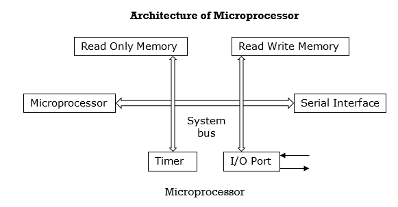
Architecture of Microcontroller
CPU | Read – only memory | Read – write memory |
Serial interface | Timer | I/o post |
Microcontroller

Introduction
ES is an electronic system, which includes single chip MC
Characteristic of ES
We use the Arduino IDE to create open and change sketches (Arduino calls programmes “sketches”.) Sketches define what the board will do.
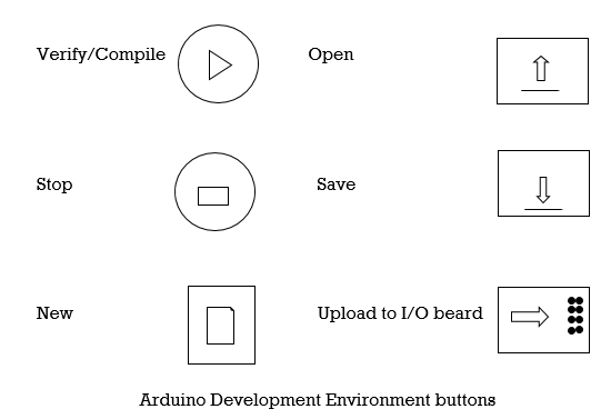
Parts of IDE
Before the program “code” can be send to the board, it needs to be converted into instructions that the board understand. This process is called compiling.
2. Stop
This stops the compilation process.
3. Create new sketch
This opens a new window to create a new sketch.
4. Open existing sketch
This loads a sketch from a file on your computer.
5. Save sketch
6. This saves the changes to the sketch we are working on.
7. Upload to board
This complies and then transmits over the USB cable to your board.
8. Serial Monitor
9. Tab button
10. This lets us create multiple files in our sketch. This in for more advanced programming.
11. Sketch editor
12. This is where we write or audit sketches.
13. Text console
This shows us what the IDE is currently doing and is also where error messages display if we make mistake in typing our program.
14. Line number
This shows what line number our cursor is on. It is useful since the compiler gives error messages with a line number.
1.5 Programming concepts: variables, functions, conditional statements
These consists the brackets, parenthesis and the assignment operator. The parenthesis is used to boost the priority of an operator.
Symbol | Precedence | Description |
{} | 1 | Brackets, used to group program statement. |
() | 1 | Parenthesis, used to establish precedence |
= | 12 | Assignment. |
The assignment (=) operator is used to assign the argument (s) on the right-hand side of equation to the lift – hand side variable.
B. Arithmetic Operations
Arithmetic operations provide for basic maths operations using the various variables.
Symbol | Precedence | Description |
* | 3 | Multiplication |
/ | 3 | Division |
+ | 4 | Addition |
– | 4 | Subtraction |
C. Logical Operations
The logical operations provide Boolean logic operations. They can be viewed as comparison operators one argument is compared against another using logical operator provided. The result is returned as a logic value of one (1, true, leigh) or zero (0, false, low). The logical operators are used extensively in program constructs and decision processing operations.
Symbol | Precedence | Description |
< | 6 | Less than |
<= | 6 | Less than or equal to |
> | 6 | Greater than |
>= | 6 | Greater than or equal to |
== | 7 | Equal to |
!= | 7 | Not equal to |
&& | 9 | Logical AND |
ll | 10 | Logical OR |
D. Bit Manipulation operations
It consists of two general types of operations, shifting operation and bitwise operation. The bit wise operations perform the desired operation on a bit – by – bit basis.
Symbol | Precedence | Description |
<< | 5 | Shift Left |
>> | 5 | Shift right |
& | 8 | Bitwise AND |
^ | 8 | Bitwise exclusive OR |
l | 8 | Bitwise OR |
E. Unary Operations
As the name implies, they require only a single argument.
Symbols | Precedence | Description |
! | 2 | Unary negative |
~ | 2 | One’s complement |
+ + | 2 | Increment |
– – | 2 | Decrement |
Type (argument) | 2 | Casting operator |
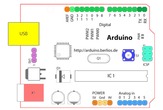
Introduction to Arduino General Purpose Board

Starting clockwise from the top centre:
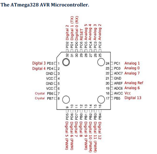
ATmega328P (used on most recent boards)
Digital I/O Pins | 14 (of which 6 provide PWM output) |
Analog Input Pins | 6 (DIP) or 8 (SMD) |
DC Current per I/O Pin | 40 mA |
Flash Memory | 32 KB |
SRAM | 2 KB |
EEPROM | 1KB |
Arduino Digital and Analog I/O Pins

Digital Pins
Pins | Function |
0 to 7 | PORT D [0:7] |
8 to 13 | PORT B [0:5] |
14 to 19 | PORT C [0:5] (Arduino Analog Pins 0 to 5) |
Digital pins 0 and 1 | RX and TX for serial communication |
Digital pin 13 | Connected to the base board LED |
