Peripheral Interface
Interfacing Diagram
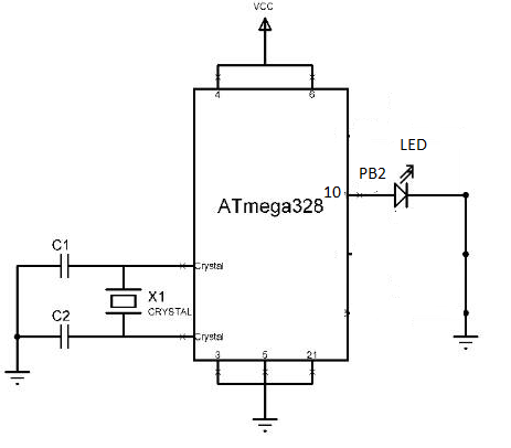
Pin Description
Device | Arduino Port | Arduino Pin |
LED1 | PB2 | 10 |
Algorithm
To interface LED to Digital pin No. 10 or PB2 pin of ATmega328.
Program
To interface LED to Digital pin No. 10 or PB2 pin of ATmega328.
voidsetup()// put your setup code here, to Initialize Pins
{
pinMode(10, OUTPUT);//Set direction of Digital Pin no. 10 or PB2 as an Output pin
}
voidloop()// put your main code here, to run code forever
{
digitalWrite(10, HIGH);//turn on LED,by sending Logic HIGH value to Digital Pin No.10
delay(2000);
digitalWrite(10, LOW);//turn off LED,by sending Logic low value to Digital Pin No.10
delay(2000);
}
ATmega328P Interfacing with LCD
The LCDs have a parallel interface, meaning that the microcontroller has to manipulate several interface pins at once to control the display. The interface consists of the following pins:

LCD Pin Description
LCD pin no. | LCD pin name | LCD pin Description |
1 | Vss | Ground pin of the LCD module. |
2 | Vcc | Power to LCD module (+5V supply) |
3 | VEE | Contrast adjustment pin |
4 | RS | Register select pin RS=0 command register. RS=1 data register. |
5 | R/W | Read/Write modes R/W=1; Read mode |
6 | EN | This pin is meant for enabling the LCD module |
7-14 | D0 to D7 | 8 data pins |
15 | LED+ | Anode of the back light LED |
16 | LED- | Cathode of the back light LED |
The process of controlling the display involves putting the data that form the image of what you want to display into the data registers, then putting instructions in the instruction register. The Liquid Crystal Library simplifies this for you so you don't need to know the low-level instructions.
Interfacing Diagram
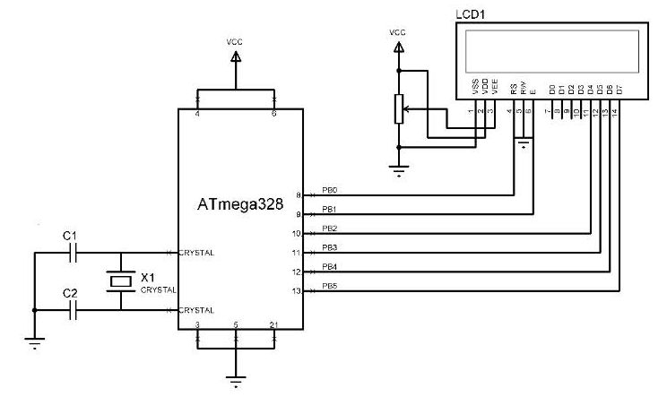
Pin Description
LCD pins | Arduino Port | Arduino Pin |
RS | PB0 | 8 |
EN | PB1 | 9 |
D4 | PB2 | 10 |
D5 | PB3 | 11 |
D6 | PB4 | 12 |
D7 | PB5 | 13 |
Algorithm
Program
To interface16*2 LCD with ATmega328 and Display the string "WikiNote Foundation" on LCD:
#include<LiquidCrystal.h>
LiquidCrystallcd(8, 9, 10, 11, 12, 13); // sets the interfacing pins
voidsetup()
{
lcd.begin(16, 2); // initializes the 16x2 LCD
}
voidloop()
{
lcd.setCursor(0,0); //sets the cursor at row 0 column 0
lcd.print("WikiNote"); // prints "WikiNote"
lcd.setCursor(2,1); //sets the cursor at row 1 column 2
lcd.print("Foundation"); // prints "Foundation"
}
Theory
1) Serial Communication
The microcontroller is parallel device that transfer 8-bit data simultaneously over 8 data lines to parallel I/O device. However, in many situation, parallel data transfer is impractical. For example, parallel data transfer over a long is very expensive. Hence, serial communication is widely used in long distance communication.
In serial data communication, 8-bit data is connected to serial bit using a parallel in serial outfisht register and it is transmitted over a single line data line. The data byte is always transmitted with least significant bit first serial port are type of computer interface for serial communication that complies with Rs=232 standard.
They are a pin connector that relay information, incoming or outgoing, one byte at a time. Each byte is broken up into a series of 8 bit, hence the turn serial port. Serial ports are controlled by a special chip called as UART (Universal Asynchronous Receiver Transmitter).
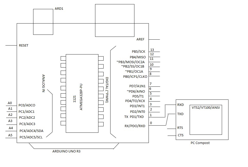
Communication Links:
Serial communication is classified into 3 types:
(a) Simplex communication link: In this, the line is dedicated for transmission. The transmitter sends and receiver receives data.
(b) Half duplex communication links: In this, the communication link can be used for either transmission or reception. Data is transmitted in only one direction at a time.
(c) Full duplex communication link: If data is transmitted in both ways at same time, it is full duplex i.e. transmission and reception can proceed simultaneously. This communication link requires two wires for data, one for transmission and one for reception.
Types of serial communication
(a) Synchronous serial data communication: In this, transmitter and receiver are synchronised. It uses a common clock to synchronise the receiver and transmitter. First, sync character is sent and then the data is transmitted. This format is generally used for high speed transmission. In synchronous serial data communication, a block of data is transmitted at a time.
(b) Asynchronous serial data transmission: In this, different clock sources used for transmitter and receiver. In this mode, data is transmitted with start and stop bits. A transmission begins with start bit, followed by data and then stop bit. For error checking purpose parity bit is included just prior to stop bit. In Asynchronous serial data communication, a single byte is transmitted at a time.
(1) Baud Rate:
The rate at which bits are transmitted is called baud or transfer rate. The Baud rate is reciprocal of time to send one bit. In asynchronous transmission, baud rate is not equal to number of bits per second. This is because each byte is preceded by a start bit and followed by parity and stop bit. For example, in synchronous transmission if data is transmitted with 9600 baud, it means that 9600 bits are transmitted in one second. For bit transmission time= 1 second/9600 = 0.104 ms.
(2) Rs232 standards:
To allow capability among data communication equipment made by various manufacturers, an interfacing standard called Rs 232 was set by Electronics Industries Association (EIA) in interfacing standard called in 1960. In 1963, it was modified and called Rs232A. Rs 232 B and Rs232Cwere issued in 1965 and 1969 respectively.
Today Rs 232 is most widely used serial I/O interfacing standard. This standard used in PCs and numerous equipment’s. In Rs 232, a logic one (1) is represented by – 3 to – 25 V and referred as MARK while logic zero (0) is represented by +3 to +25 V and referred by SPACE. For this reason, to connect any Rs 232 to a µc system we must use voltage converters such as MAX 232 to convert the TTL logic level to Rs 232 voltage levels and vice versa. MAX 232 IC chips are commonly referred as line drivers.
3) Algorithm:
(i) In setup function-
(a) Initialize serial port with desired baud rate. (e.g. 9600)
(b) Transmit the initial messages.
(ii) In Loop function-
(a) Declare the variable with data type integer to hold the received data.
(b) Check for any data is received on serial port.
(c) If yes, read the data into variable and retransmit the data on serial port.
Program:
/*
This is sketch displays text sent over serial port the circuit.
*LCD Rs pin to digital pin 2
*LCD enable pin to digital pin 3
*LCD D4 pin to digital pin 4
*LCD D5 pin to digital pin 5
*LCD D6 pin to digital pin 6
*LCD D7 pin to digital pin 7
*LCD R/W pin to ground.
*10 k register.
*Ends to +5V and ground.
*Wipes to LED Vo pin (pin 3)
*/
// include the library code;
# include <Liquid crystal.h>
// Initialize the library with no. Of interface pins.
Liquid Crystal LED (2,3,5,6,7)
Void Setup() {
// set up LCDs no. of columns and rows led begins(16,2)
// initialize serial communication serial begin(9600)
Led begin (“smarr Logic Tech”);
Led set cursor (0,2);
Led print (“LCD interface “);
Serial poin in (“Smart Logic Tech”);
Serial point in (“Send data to be displayed on LCD”);
}
Void loop ( ) {
// When character arriveover serial port if serial available( )
// wait a bit for entire message to arrive delay (100);//Clear the screen
LCD clear( )
// read all available characters
while (serial available characters ( )>0) {
//display each character to LCD, LED write
(serial read());
}
}
}
Conclusion:
From this experiment we learn about programming to transfer the manage and receive in 8 bit -1 stop bit.
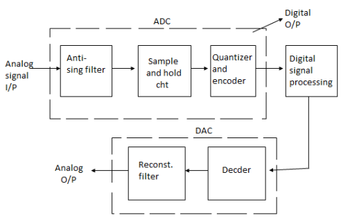
ADC (Analog to Digital Convertor) And DAC (Digital to Analog Convertor)
1) Most of the physical quantities such as temperature, pressure, displacement, vibrations are in the analog form but it is difficult to process, store or transmit the analog signal because of noise.
2) In order to reduce the errors, it has to represented into digital form.
ADC and DAC are the Duta converter circuits and they are available in IC form.
Principle:
1) Analog signal is a signal having continuous values. They can have infinite number of different values. E.g. Temperature, pressure.
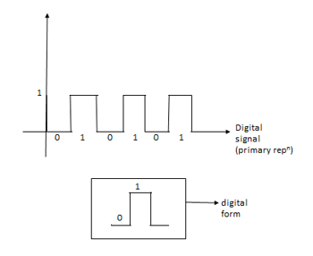
2) The Digital Signal is a signal that has finite number of distinct values.
3) Digital signals are not continuous signals they are binary representation the digital signals have to Slates i.e. 0 & 1.
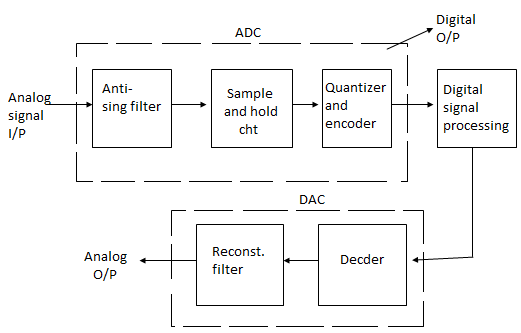

Conversion of digital signals from ADC
Sampling:
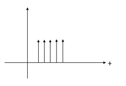
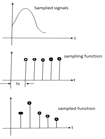
1) Input analog signal is sampled over a period of time by sample and hold circuit.
2) I/p to s/H circuit is the sampling fuse. The sampling fuse is the train of impulses. An impulse is a signal that has some value during S/H circuit multiplies the analog signal and the sampling fuse in order to produce the sample signal. After the signal is sampled it is called as Discrete signal.

Quantization: - Dividing the sampled or discrete signals into two discrete levels. These discrete levels are usually powers of 2.
For a ‘n' bit, no. of quan levels are  .
.
Quantized Round Off each sample
8=  n=3
n=3
ADC :
1) ADC in ATmega 328p is 10 bit.
2) It has 6 registers.
3) This ADC is provided on chip or on boardbof MC.
ADC Register:
1) ADMUX Register
2) ADCSRA (ADC control status Regr. A
3) ADCSRA (ADC control status Rege. B)
4) ADCH (High data) Regr.
5) ADCL (Low data) Regr.
6) DIDRO- Digital i/p Digital Regr. O.
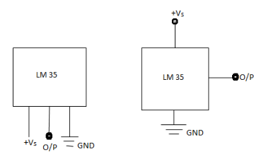
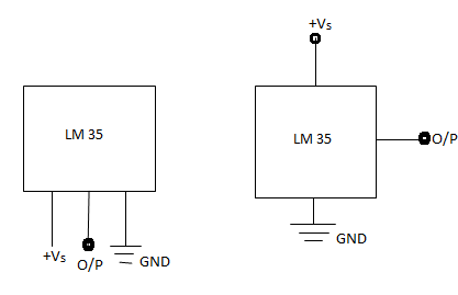
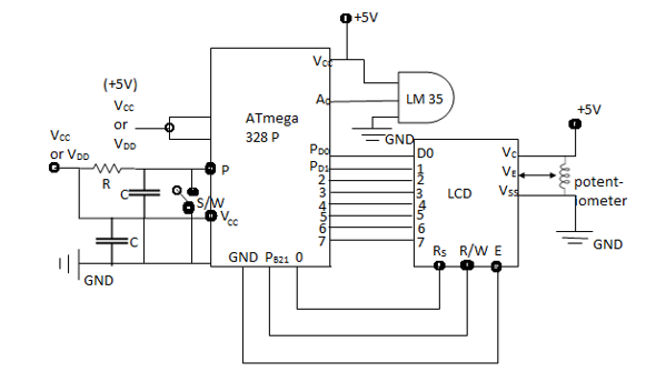
LM 35
Interfacing with Arduino and displaying O/P on LCD
1) Temperature is a physical parameter. In most of temperature sensors the temperature value is converted into electrical value.
2) These sensors are the key to read the temperatures correctly and to control temperature in industrial applications.
3) LM35 is a precision Integrated circuit temperature sensor whose o/p voltage is linearly proportional to the Interfacing with Fahrenheit or Celsius temperature.
4) It does not require any external calibration or trimming to provide typical accuracies.
5) It can operate in in between 55 degrees Celsius to 150 degrees Celsius.
6) It has an o/p of 10mV for each degree Celsius or Centigrade. For e.g. 80°C temp. with an o/p will be 10mv × 80= 800mV.
Temperature Measurement
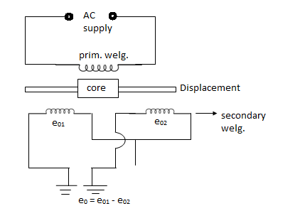
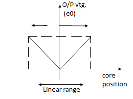
Principle: LVDT produces a differential voltage at the o/p i.e. e°=e°1-e°2 which is proportional to the displacement or position of the core from its null position. Thus, a voltage proportional to displacement of core is obtained at the LVDT o/p.
Example: - Null vtg., resolution, linearity, senstivity, Dynamic Response, onvtg.
1) A strain gauze is a passive sensor/transformer that converts the applied force of an object to electric resistance.
2) They are frequently used in in Mechanical energy to measure the stress generated by machinery.
3) Electronic weighing w/c use. Load cell to measure the load or pressure produced by the load.
4) A load cell measures load using strain gauze and a strain gauge converts the pressure to electrical signal.
A load cell measures load using strain gauze and a strain gauge converts the pressure to electrical signal. 
References
1. Electric Vehicle Technology Explained Book by James Larminie
2. Modern Electric, Hybrid Electric, and Fuel Cell Vehicles: Fundamentals, Theory, and Design
3. Electric and Hybrid Vehicles: Design Fundamentals, Second Edition Textbook by Husain Iqbal