DC Machines
a) It is based on Dynamically(rotating) induced Emf
b) It is based on faraday is Law of Electromagnetic Induction.
c) If the flux linkage with a conductor changes due to the relative motion between magnetic field and conductor then the Emf is induced in conductor.
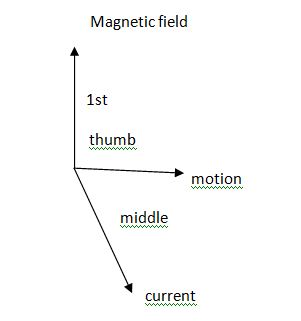
d) The direction of DC Generator is given by Fleming’s Right hard Rule.
Flemings Right H.R.
If the 1st finger points – Magnetic field (Flux) Thumbs shows the direction of – Motion.
‘Then’
The middle or central finger shows direction – current
Image
3.2 Constructional features of a DC machine
Following fig. shows construction of a DC m/c. The construction is same for DC motor as well as DC generator.
Image
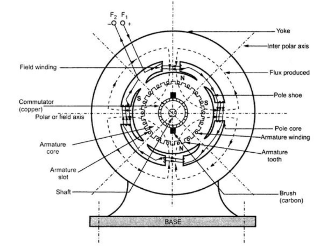
It is the magnetic frame of the m/c it provides protection to the internal parts of the m/c, it is the outer covering of m/c. The yoke carries the yoke flux ( ). It is also providing the mech. Support to the m/c.
B. Armature:
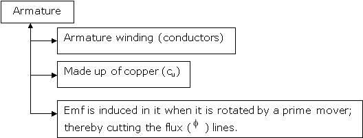
It is the rotating part of the m/c which houses the armature conductors, Armature winding. These conductors are made up of copper (Cu).
Armature conductors are interconnected for forming the Armature winding.
Armature winding is connected to external cut or load.
C. Field winding (f1, f2)
a) It is wounded on the poles or pole wires in the form of a coil.
b) It provides the path for ‘If’ field current in a specific direction.
c) It is also called as the exciting winding.
d) Material used for field winding is copper i.e. cu.
D. Commutator
a) It is a cylindrical drum mounted on shaft.
b) It consists of copper segments.
c) It is made up of segments of hard drawn copper.
d) These segments are insulated with thin layer of mica.
e) Function: It converts the A.C voltage generated internally in D.C. voltage o/p.  it acts as a rectifier.
f) It collects the current from Arm conductors.
E. Brushes
(Mall used carbon or Graphite)
a) Current is conducted to the armature to the external load by carbo Brushes.
b) It provides the path to the flow of current. They are Rectangular in shape.
F. Armature Windings:
Provided over armature the drum.
a) Lap Winding  A = P
A = P
b) Wave Winding  A = 2
A = 2
Where,
A = Total No. of Parallel paths in the Armature
P = No. of Poles
G. Pole, Pole shoe and Pole core:
Image
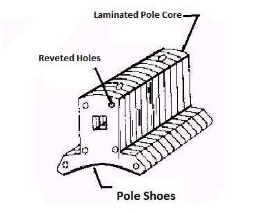
a) Pole are electromagnet. Field winding is provided over it.
b) Poles produce the magnetic flux ( )
)
c) Pole shoe is the extended part of pole.
d) A low Reluctance (s) Material is used for pole or pole shoe such as cast steel or cast iron pole core is the covering of poles.
e) Shaft:
f) It is the innermost part in the m/c  it is the rotating part of the m/c.
DC Generator – Mechanical Energy (I/P) Electrical Energy (O/P)
For example prime mover is a Diesel Engine or turbine.
Let us consider diesel Engine coupled–drive the Arm (Armature drum)
Thus, the Armature (Winding, conductors) cuts the Magnetic lines of Fluxes ( ) and an Emf is induced.
Let,
P = No. of poles of Generator
 = Flux produced by pole in ‘wb’.
N = Speed in RPM at which generator rotates.
Z = No. of conductors in Arm winding.
A = No. of parallel paths in Arm.
Thus, According to paraday’s Law of Electromagnetic induction emf induced in conductor is given by
 … (1)
… (1)
For one complete Revolution of a conductor flux cut by conductor is ( ) wb and time Required to complete one revolution is
  seconds.
 the equation (1) becomes
 … (2)
… (2)
As the No of conductors in Armature is ‘Z’
 Parallel paths are ‘A’ thus thee are
  conductors in each group.
 Equation (2) becomes,

 - Emf equation of generator (DC)
Generated Emf E > V (Supply voltage (Armature))
Voltage Equation of DC (m) is given by:-
 … (1)
… (1)
We know power, P = V.I
Multiply both sides by ‘Ia’ current
 … (2)
… (2)
Where,
V.Ia = Element power  to Armature
 = Copper losses in the Armature (Losses)
EbIa = Element pr. Equivalent of mech. Pr. Produced (Pm) 
 … (3)
… (3)
T = Torque – Turning or Twisting Action or Movement of conductor
T =F x d = (N.m)
 = Angular velocity in (Rotation of Conductor) = (rad/sec)
Thus Power ‘pm’ is given by, also

But 
 … (4)
… (4)
But,  … (5)
… (5)
Substitute (5) equation in (4) we get,


 (P, z, A = constant)
 = Constant value = K


Problems:
DC Generator
A 480V DC Generator has 4 poles and Armature drum has 96 slots, each carrying 10 conductors. When flux per pole is 25.2 mwb, 2mf induced in the wave winding (Armature) is 484V, determine the speed at which the generator is driven. If the current carrying capacity of Armature conductor is 1.3A what is kW rating of the generator?
Answer:
Z = 96 x 10 = 960 conductors,
E = 484 V
N =  , where A = 2 (Wave winding)

kW = P = V.I; V = 480V Given
kW = P = 
kW = P = 1.25 kW
Image
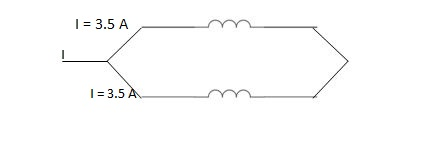
I = 1.3 A + 1.3 A
or A = 2 Parallel paths.
Thus I = 2 x 1.3 A
I = 2.6 A
Total, I = 2.6 A

Problem
DC Motor
A 250V, dc shunt motor has an Armature Resistance of  and filed resistance of
  it drives a load of 1000 rpm and takes a current of 25A. The field cut resistance is then increased to
  . Calculate then now speed, Assume load torque constant.
Solution:
V = 250 V
Ra = 
Rsh1 = 
N1 = 1000 rpm,
I1 = 25 A
Rsh2 = 
T1 = T2
N2= ?
One formula missing

 ;
;  .
.


 ;
;  ;
; 

 .
.
Problems for Practice:
A 250V dc shunt motor draws a current of 21 Amp. For given load torque and runs at 1500 rpm. Its field resistance is  & Armature resistance is
 Calculate the new speed with which motor runs if
  resistance is connected in series with field winding. Assume load torque remains constant.
Given:
V = 250v
IL1 = 21 A
N1 = 1500 rpm
Rsh1 = 
Ra1 = 
Rsh2 = 250 + 250 = 
N2= ?
For Ia1= ?

Ish2= ?

 .
.
Ia2= ?


 ;
; 


 .
.


Given:
V = 200 V,
Lap wound A = P,
Z = 800 conductors


IL = 21A


DC motor is used to produce rotational kinetic energy by exerting torque on the load. This Torque which exerts upon the load through its shaft is called the load torque.
Initially it produces torque through electromagnetic interaction between stator field and current carrying conductors of the rotor to produces the torque called “Electromagnetic Torque”. This torque supplies the friction and windage losses of the machine and then feeds the load.
T (Electromagnetic) = T (Friction, Windage, etc.) + T (Load)
Now, for the same power, if the speed of the motor is increased, then output torque required to keep it moving further decreases and hence torque decreases.
And if the motor speed is lowered, for the same output, the motor torque increases which is given by.
Power = Torque * Speed = T* 2πN/60;
That constant power output curve follows the hyperbolic relation between the torque and the speed of the motor.

The three motor load types are:
Dynamics of motor and load combination
The motor and the load that it drives can be represented by the rotational system shown in Figure. Generally, the load may not rotate at the same speed as the motor, therefore it is convenient to represent it in this manner so that all parts of the motor-load system have the same angular velocity.
If the speed of the load differs from motor, one can find out an equivalent system.

The basic torque equation, known as the equation of motion, for the above motor-load system, is written as
TM = TL+ J dw/dt where TM and TL denote motor and load torque measured in N-m; J, the moment of inertia of drive system in kg-m2 and , the angular velocity in mechanical radians/sec.
In the above equation the motor torque is considered as an applied torque and the load torque as a resisting torque.
From the above equation, it is possible to determine the different states at which an electric drive causing rotational motion can remain.
(i)If TM > TL, i.e., d/dt > 0, the drive will be accelerating, in particular, picking, up speed to reach rated speed.
(ii) TM < TL, i.e., d/dt < 0, the drive will be decelerating and, particularly coming to rest.
(iii) TM < TL, i.e., d/dt = 0, the motor will continue to run at the same speed, if it were running or will continue to be at rest, if it were not running.
Image
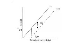

But 


As the torque is directly prop. To ‘Ia’ both the value 
2. Speed – armature current c/s:-
N – Ia c/s:-
Image
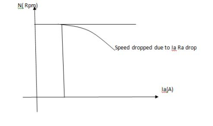


Speed ‘N’ is inversely proportional to ‘Ia’
 As ‘N’ speed
  the ‘Ia’
  & vice versa.
3. Speed – Field current Ip (shunt) c/s:
N – IF (shunt) c/s:-
N – IF (shunt field) c/s:-
Image
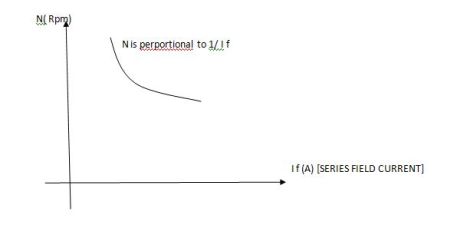


Speed ‘N’ inversely proportional to ‘IF’ (shunt field) thus as ‘N’  ‘IP’
‘IP’  & vice versa.
4. Speed – Torque c/s:
N – T c/s:
Image
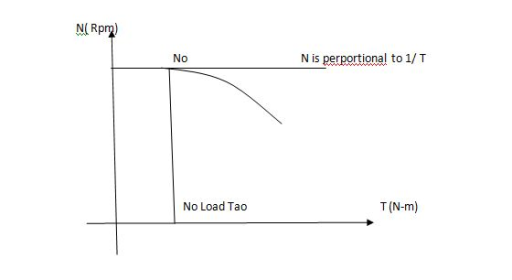


This c/s is similar to speed ‘N’ – Ia c/s.
 No load speed (RPM)
Or sometimes the N – T c/s will be as given below
As ‘N’ inversely prop. To ‘T’
 As N
As N  T
T  & vice – versa.
Characteristic of DC series Motor:
Image
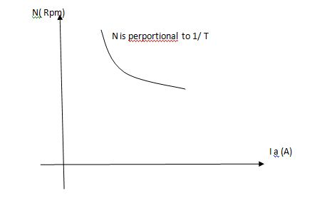


T = Ta = Armature Torque
Tsh = Shaft torque.
 – Lost torque


2. N – Ia c/s:-
Image
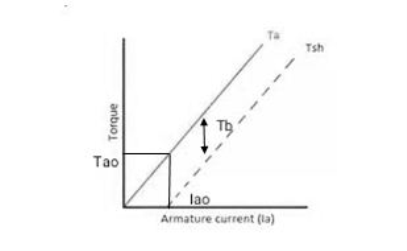

 ;
; 


As  because of inverse proportionality.
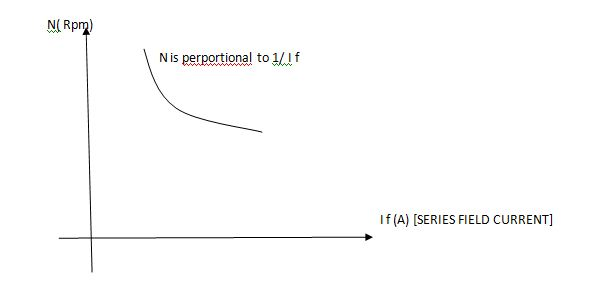
3. N – IF (Series Field current) c/s:
Image
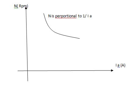


As ‘N’ inversely prop. To IF (series field)
 and vice – versa.
4. N – T c/s:-
Image

 ;
; 

As  Inverse proportionality.
Why series Motor Never Started on No – Load?
As we know that

In No – load condition ‘Ia’ current is very small and ‘ ’ flux is also small.
 The speed a no-load condition becomes drastically high which can damage the shaft of motor and mtor winding also.
Stator:
Need of Starters:
As we know
 … (1)
… (1)
Also,  … (In case of DC motor) … (2)
From equation (2), (1) we can also write;

 …
… 

 From Equation (2)
(Starting) 

At the standstill condition of DC motor, the back emf 
& the armature Resistance value is very less i.e. in both 0.8 + 0.9
 .
.
Thus,

 .
.
As ‘Ra’ is very small the ‘Ia’ (starting) current increase to very high value in order to avoid the high starting ‘Ia’ current the starters are used.

To avoid this use starters.
Types of Starters:
For DC Motors:
Normally the 3 – point starter is used for DC shunt motors.
And the other starters are used for the DC series motors and other motors.
Considering DC shunt Motor
Image
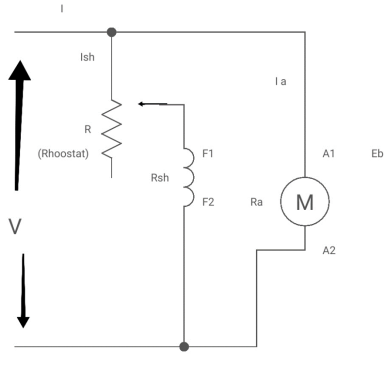
As we know, 
But 

 Thus
Thus 
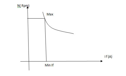
 (min. value pt.) the ‘IF’
  (Inversely proportional)
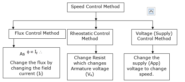
The change in Flux is achieved by changing ‘IF’ by Varying position of Rheostat ‘R’ from min to max. Thus speed ‘N’ Also charges (min. to max).
Graph:
N Vs IF
Image
2. Rheostatic control method:
Changing Armature voltage (Va) To control ‘N’ speed.
Considering DC shunt Motor:
Image
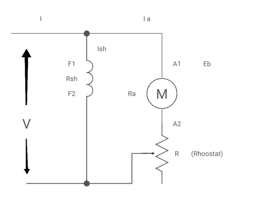
By varying the value of Resist. ‘R’ we can vary the voltage ‘Va’ i.e. Across the armature i.e. Armature voltage.


 But also


Graph:
Image
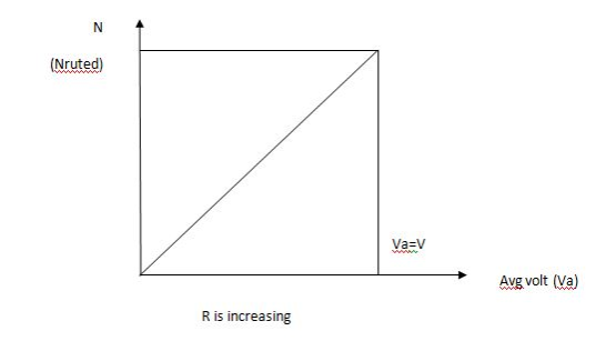
As  or
or  so it is possible to change the speed N by varying the value of Rheostat ‘R’.
3. Voltage (Applied) control Method:-
Considering the DC series Motor:
Image
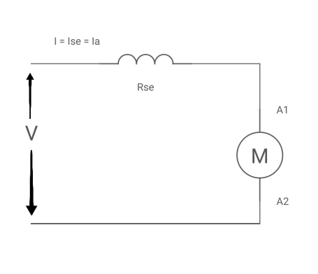

 .
.
As, 


 as per the equation
As 


As per the equation  speed increases as App. Voltage is increased.
Below rated speed is possible.
To reverse the motor, the polarity of the supply voltage must be changed to either the field winding or the armature winding, but not both. Generally, it is better to reverse the field voltage because the field current is less than the armature current, so reversing switchgear is more lightweight.
If the field terminals and armature terminals cannot be separated, then reversing cannot be done.
For a brushless DC motor, reversing the supply polarity will not work and possibly damage the motor.
Electrical Braking is employed in applications to stop a unit driven by motors in an exact position or to have the speed of the driven unit suitably controlled during its deceleration.
Electrical braking is used in applications where frequent, quick, accurate or emergency stops are required.
There are three types of Braking :-
Regenerative Braking
It is a form of braking in which the kinetic energy of the motor is returned to the power supply system. This type of braking is possible when the driven load forces the motor to run at a speed higher than its no-load speed with a constant excitation.
The motor back emf Eb is greater than the supply voltage V, which reverses the direction of the motor armature current. The motor begins to operate as an electric generator.
Dynamic Braking
It is also known as Rheostatic braking. In this type of braking, the DC motor is disconnected from the supply and a braking resistor Rb is immediately connected across the armature. The motor will now work as a generator and produces the braking torque.
During electric braking when the motor works as a generator, the kinetic energy stored in the rotating parts of the motor and a connected load is converted into electrical energy. It is dissipated as heat in the braking resistance Rb and armature circuit resistance Ra.
Plugging
It is also known as reverse current braking. The armature terminals or supply polarity of a separately excited DC motor or shunt DC motor when running are reversed. Therefore, the supply voltage V and the induced voltage Eb i.e. back emf will act in the same direction.
The effective voltage across the armature will be V + Eb which is almost twice the supply voltage.
Thus, the armature current is reversed, and a high braking torque is produced. Plugging is a highly inefficient method of braking because, in addition to the power supplied by the load, the power supplied by the source is wasted in resistances.
Regenerative braking in DC shunt motor
In Regenerative Braking, the power or energy of the driven machinery in kinetic form is returned to the power supply mains. This type of braking is possible when the driven load or machinery forces the motor to run at a speed higher than the no-load speed with constant excitation.
The excitation of the motor is increased as the speed is reduced so that the two equations shown below are satisfied.
Eb = nPɸZ/A and V = Eb – Ia Ra
The motor does not enter into saturation on increasing excitation.
Under normal operating conditions the armature current is given by the equation shown below:
Ia = V – Eb/ Ra
When the load is lowered by a crane, hoist or lift causes the motor speed to be greater than the no-load speed, the back EMF becomes greater than the supply voltage. Consequently, armature current Ia becomes negative. The machines now begin to operate as a generator.
References
1.Electric Vehicle Technology Explained Book by James Larminie
2.Modern Electric, Hybrid Electric, and Fuel Cell Vehicles: Fundamentals, Theory, and Design
3.Electric and Hybrid Vehicles: Design Fundamentals, Second Edition Textbook by Husain Iqbal
