Three Phase Induction Motors


Construction:
I.M. consists of two main parts
Stationary  winding Part Called ‘stator’
2. Rotor
Rotating part & is connected to mech. Load through shaft called ‘Rotor’.
1) Stator
The stator has laminated type of construction made up of stamping which are 0.4 to 0.5 mm thick.
a) The stampings are slotted on its periphery to carry stator windings the stampings are insulated from each other.
b) The no. of stampings is stamped together to build stator core.
c) The built-up core is then fitted in casted or Fabricated steel frame. The material of stampings is silicon steel because it minimizes hysteresis loss.
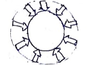
d) The stops on periphery of stator core carries a  winding, connected either in star or delta, this
  winding is called stator winding.
e) The radial ducts are provided for cooling purpose.
2) Rotor
There are two types rotor Construction.
a) Squirrel cage rotor
b) Slip ring or phase wound
a) Squirrel cage rotor:

a) The rotor core is cylindrical and slotted on its periphery.
b) The rotor consists of uninsulated cu or Al bars called ‘rotor conductors. The bars are paced in the armature slots.
c) These bars are permanently shorted at each end with the help of conducting ring called ‘end ring’. The bars are brazed to end rings to provide good mechanical strength.
d) The entire structure looks like a cage, forming a closed ckt, so rotor is called squirrel cage rotor.’
e) As the bars are permanently shorted to each other though end ring, the entire rotor resistance is very small. Hence rotor is called ‘short circuited rotor’.
f) As rotor itself is short drauited, no external resistance can have effect on rotor resistance so external resistance is inserted.
g) In this type of rotor, slots are not arranged parallel to shaft axis but they are skewed.
Advantages of Skewing:
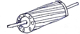
a) Magnetic hum (noise) gets reduced
b) Makes motor operation smooth.
c) Stator and rotor teeth may get magnetically locked, due to skewing it is reduced almost.
d) Increases the effective transformation ratio between stator and rotor.
b) Slip Ring Rotor or Phase wound Rotor:
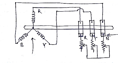
a) In this type, rotor winding is exactly similar to stator the rotor carries  Y or
Y or  connected, distributed winding wound for some number of poles as that of stator.
b) The rotor construction is terminated and slotted, the slots contains the rotor winding.
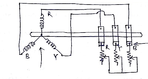
c) The 3 ends of  winding available after connected the winding in
  are permanently connected slip rings.
d) With the help of slip rings, external resistance can be added in series with each phase of rotor winding.
e) In running condition, the slip rings are shorted
f) The possibility of addition of external resistance in series with rotor, is the main feature of this type rotor.
Difference Between
Slip Ring/ Wound | Squirrel Cage |
1) Rotor and stator have similar | 1) Rotor consists of bars with end rings |
2) Construction is complicated | 2) Construction is very simple |
3) External resistance can add | 3) External resistance can’t add |
4) Rotors are very costly | 4) Rotors are cheap |
5) Slip ring and brushes are present | 5) Slip ring and brushes are absent |
6) High starting torque can be detailed | 6) Moderate starting torque. |
Working Principles


 = Speed of rotating magnetic field.
C. This rotating magnetic field produces on effect of rotating poles around a rotor.
D. Let direction of rotation of this rotating magnetic field is clockwise. (Fig a)

Now at this instant rotor is stationery and stator flux RMF is rotating. So, it’s obvious that there exists a relative motion between RMF and motor conductors.
E. Whenever conductor cuts the flux, emf gets induced in it.
F. As rotor forms closed circuit, induced emf circulates current though rotor called rotor current fig.(b).
G. Any current carrying conductor produces its own flux, called rotor flux fig. (c).
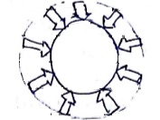
H. Both fluxes interact each other as shown in fig (d)
I. On left of rotor conductor, two fluxes are in same direction hence add each other. While on ri9ght side of rotor, fluxes cancel each other to produce low flux area.
J. High flux density area exerts a push on rotor conductor towards low flux density area, so rotor conductor experiences forces from left to right fig. (d)
K. As all rotor conductors experience a force, the overall rotor experiences a torque and start rotation so interaction of fluxes is very essential for a motion action.
L. The cause of rotor current is the induced E.M.F which is induced because of relative motion present between rotating magnetic field and rotor conductors.
M. To oppose relative motion i.e. to reduce relative speed, rotor experiences a torque in same direction as that of RMF and tries to catch up the speed of rotating magnetic field.
N. NS = Speed of rotating magnetic field.
N = Speed of rotor i.e. motor speed in rpm (NS – N) = Relative speed between two, rotating magnetic field and rotor.
O. Thus, rotor always rotates in same direction as that of RMF. (N < NS).
Slip of Induction Motor


N = NS()
Can NS = N
Also, Never NS> N
The slip affects the rotor parameters when an I.M runs with speed N rpm.
The various parameter which gets affected by the slip are-
1) Effect on Rotor Frequency
At start speed of I.M. is zero (N = 0) & slip s = l.
Then the frequency of rotor induced emf is same as the stator supply frequency.
If
Fr = Frequency of rotor induced emf
f = Stator supply frequency
Fr = F at start when S = l.
But when motor rotates at speed N, there exists a slip S & then in running condition, frequency of rotor induced emf is slip times the stator supply frequency.
Fr = Sf … in running condition
As slip is small, Fr is very small in
2) Effect on magnetic of rotor induced emf
Let
E2 = Rotor induced emf/ Ph in stand still
While
E2r = Rotor induced emf/ Ph in running
The induced emf depends on relative motion between rotor &RmF.
It is max. at start hence E2 is max at start.
In running condition, relative speed becomes Ns – N hence induced emf reduce, by slip times. The max. emf E2 at stand still.
E2r = SE2
3) Effect on Impedance
Let,
R2 = Rotor resistance/ ph. On standstill condition.
X2 = Reactance
Z2 = R2 + jx2 = Rotor imp. On stand.(N = 0)
In running condition, rotor frequency. (Fr = SF)
Hence,

Hence rotor imp. In running condition (Z2r) is
Z2r = R2 + jx2r = R2 + js x 2
4) Effect on Rotor P.F.
The P.F. is the ratio of R toZ

While in running condition,  changes to
  . Hence P.F. in running condition is given by

5) Effect on rotor current
The ratio of rotor induced emf to rotor imp. Is the rotor current.
Hence rotor current on stand still is

While in running condition, E2 changes to SE2 and  changes to Z2r hence rotor current becomes.

Torque Equation
The torque produced in I.m depend on following factors
1) The port of RMF which react with rotor & is responsible to produce .
.
2) The magnetic of rotor current in running condition.
3) The P.F. of rotor ckt in running condition.
Mathematically, the relationship can expressed as
 … (1)
… (1)
 = Flux responsible to produce induced emf
I2r = Rotor running current.
 = Running P.F. of rotor
The flux  produced by stator is proportional to E1 i.e. stator voltage.
 … (2)
… (2)
While E1 and E2 are related to each other through ratio of stator runs to rotor turns i.e.
 … (3)
… (3)
Using equation (3) in (2) we can write

Thus, in equation (1)  can replace by E2
Also


Where K = constant of proportionality.
The constant K is proved to be  for
for  I.M.
I.M.

Where,
ns = syn. Speed in rps = 
where NS in rpm

Case I
Starting Torque
A) Starting torque is nothing but the torque produced by an I.m at start
At start, N = 0 & slip S = 1

From the above equation it is clear that by changing R2, the starting torque Tst can be controlled.
B) The change in R2 at start is possible in case of slip ring I.m. only.
This is the principle used in case of slip ring I.m. to control starting torque Tst.
Case II
Condition for max. Torque (Tm)
A) The only parameter which controls torque is slip S other parameters E2, R2, X2& ns are constant.
B) Mathematically for the max. torque e can write,
 where,


 Taking
  con.
con.


This is the slip at which torque is max. and is denoted as Sm

It is the ratio of standstill rotor resistance and reactance.
Case III
Magnitude of Max. Torque
This can be obtained by putting
 in the torque equation.


 N.m.
N.m.
It is observed that Tm is -
Torque slip characteristic
1) As the I.M. is loaded from no load to fall load it’s speed decreases hence slip increases.
2) Due to increased load, motor has to produce more torque to satisfy load.
3) The torque ultimately depends on slip.
4) The behaviour of motor can be easily judged by sketching a curve obtained by plotting torque produced against slip of I.M.
5) The curve obtain by plotting torque against slip from S = 1 (at start) to S = 0 (at syn. Speed) is called torque slip chs. of the I.M.
We have seen that for a constant supply voltage, E2 is also constant.
We can write torque equation as

6) To judge the nature of torque – slip ch. Let us divide the slip range S = 0 to S = 1 into two parts and analyse them independently.
Low Slip Region
In this region, S is very small.
Due to this the terms (SX2)2 is so small as compared to  that it can be neglected.

Hence in low slip region torque is directly proportional to slip. So as load increases, speed decreases, increasing the slip.
This increases the torque which satisfied load demand.
Hence the graph is st. line in natue.
At N = Ns, S = 0, hence T = 0
As no torque is generated at N = Ns, motor stops. If it trial to achieve the syn. Speed.
Torque increases linearly in this Regin, of low slip values.
High slip Region
In this region, slip is high i.e. slip value is approaching to 1, Here it can be assumed that the term  is very small as compared to
Hence neglecting  from the denominator
 T where R2& X2 are constants.
So in high slip region torque is inversely proportional to the slip. Hence its nature is like rectangular hyperbola.
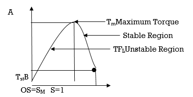
OA = Stable Region
AB = Unstable Region
A = Maximum Region
B = Starting Torque
C = Full and Torque
Effect of change in Resistance on Torque
We know that in slip ring I.M. externally resistance can be added in the rotor.
Let, R2 = rotor resistance per ph.

Now externally resistance is added in each phase of rotor thro slip rings.
Let  = Now rotor resistance per phase.

Similarly starting torque at s = 1
For  can be written as

Maximum Torque 
TM Max. Torque Line
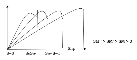
In slip ring induction motor, externally resistance can be added in the rotor.
To see the effect of change in rotor resistance on the torque produced.
The torque produced by an induction motor is given by
T = KT s α / (s2 + α2)
where KT is torque constant = 3 (E1)2 / ωs X’2
And α is the machine constant = R’2 / X’2
Now when an external resistance is added up in series with rotor then
Let ‘x’ represent per phase value of inserted resistance in series with rotor then the machine constant α gets changed or increased to a new value.
Hence value of slip corresponding to maximum torque smax is equal to α gets shifted.
Therefore,
smax = ( R’2 + x ) / X’2
Tm = KT / 2 (When s = α) = 1.5 (E1)2 / ωs X’2
It is observed that Tm is independent of R’2 hence whatever may be the rotor resistance, maximum torque produced never changes but the slip and speed at which it occurs depends on R’2.
Because of this we get a new torque – slip characteristics for rotor resistance ( R’2 + x ).
This new characteristics is parallel to the characteristics for with same Tm but occurring at different value of slip.

Effect of rotor resistance on torque-slip curves
From the figure it can be seen that the starting torque T’st for R’2 is more than Tst for ( R’2 + x ) . Thus by changing rotor resistance the starting torque can be controlled.
The Deep Bar Rotor in an induction motor is used to obtain high rotor resistance at starting and low rotor resistance at the running condition. The figure below shows a deep bar cage rotor with deep and narrow bars.
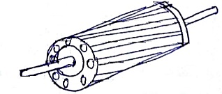
A bar is assumed to be made up of a number of narrow layers connected in parallel. The figure shows three layers A, B and C.
The topmost layer element that is denoted by A is linked with the minimum leakage flux. Its leakage inductance is minimum.
The bottom layer C links with the maximum leakage flux and thus, its leakage inductance is maximum.
At the starting, the frequency of the rotor is equal to the supply frequency. The bottom layer element C offers more impedance to the flow of current than the top layer element A. Hence maximum current flows through the top layer and minimum current flows through the bottom layer.
The effective rotor resistance increases, and the leakage reactance decreases, because of the unequal current distribution of the current. The starting torque and the starting current are higher and lower, respectively because of the high rotor resistance at the starting condition.
Under normal operating conditions, the value of a slip and the frequency of the rotor is too small. The reactance of all the layers of the bars is small as compared to their resistances.
The impedance of all layers of the bar is nearly equal, so the current flows through all parts of the bar equally. The rotor resistance of the motor is small because of the large cross-sectional area which makes the rotor resistance small, resulting in a better efficiency at the lower slip.
Power stages
The input fed to the stator of the motor is converted into mechanical power at the shaft of the motor. The various losses during energy conversion are:
(i) Field losses
(ii) Stator iron loss
Friction and windage loss
The rotor iron loss is negligible because the frequency of rotor currents under normal running condition is small.
Variable losses
(i) (i)Stator copper loss
(ii) Rotor copper loss
The figure shows how electric power fed to the stator of induction motor suffers losses and finally converted into mechanical power.
The following points are noted from the above diagram
(i) Stator input
Pi = Stator output Stator losses
= Stator output Stator Iron loss Stator Cu loss
(ii) Rotor input
Pr = Stator output
Because the stator output is entirely transferred to the rotor through air gap by electro magnetic induction.
(iii) Mechanical power available
Pout = Pm – Friction and windage loss
Mechanical power available at the shaft produces a shaft torque Tg.
(iv) Mechanical power at shaft
Pout = Pm – Friction and windage loss
Mechanical power available at the shaft produces a shaft torque Tsh.
Pm – Pout = Friction and Windage loss
Variable Frequency Control is the method used to control the speed of an induction motor.
The synchronous speed and therefore, the speed of the motor can be controlled by varying the supply frequency.
The synchronous speed of an induction motor is given by the relation shown below.
Ns = 120f/P
The EMF induced in the stator of the induction motor is given by the equation shown below.
E1 = 4.44 kw1 fɸ T1
Hence if the supply frequency is changed the induced EMF will also change in order to maintain the same air gap flux.
The terminal voltage V1 is equal to the induced EMF E1 if the stator voltage drop is neglected.
To minimise the losses and to avoid the saturation, the motor is operated at rated air gap flux. This condition is obtained by varying the terminal voltage with frequency so as to maintain (V/f) ratio constant at the rate value. This type of control is known as Constant Volts Per Hertz.
Thus, the speed control of an induction motor using variable frequency supply requires a variable voltage power source. The variable frequency supply is obtained by the following converters.
Variable frequency drive
The VFD consists of three stages for controlling a three -phase induction motor.
Rectifier Stage
A full-wave power diode based solid-state rectifier converts three-phase 50 Hz power from a standard 220, 440 or higher utility supply to either fixed or adjustable DC voltage. This system may include transformers for high voltage system.
Inverter Stage
Power electronic switches such as IGBT, GTO or SCR switch the DC power from rectifier on and off to produce a current or voltage waveform at the required new frequency.
However, most of the voltage source inverters (VSI) use pulse width modulation (PWM) because the current and voltage waveform at output in this scheme is approximately a sine wave.
Power Electronic switches such as IGBT, GTO etc. switch DC voltage at high speed, producing a series of short-width pulses of constant amplitude. The output voltage is varied by varying the gain of the inverter. The output frequency is adjusted by changing the number of pulses per half cycle or by varying the period for each time cycle.
The resulting current in induction motor simulates a sine wave of the desired output frequency.
The high -speed switching action of a PWM inverter results in less waveform distortion and hence decreases harmonic losses.
Control System
The function of the control system is to control output voltage that is voltage vector of inverter being fed to motor and maintain a constant ratio of voltage to frequency (V/Hz).
It consists of an electronic circuit which receives feedback information from the driven motor and adjusts the output voltage or frequency to the desired values.
References
1.Electric Vehicle Technology Explained Book by James Larminie
2.Modern Electric, Hybrid Electric, and Fuel Cell Vehicles: Fundamentals, Theory, and Design
3.Electric and Hybrid Vehicles: Design Fundamentals, Second Edition Textbook by Husain Iqbal
