Unit 1
Simple Stresses and Strains
Mechanics deals with both moving and stationary bodies that are influenced by various Forces. When a force acts on a structure it becomes load to that particular structure. These loads can be classified as Static, Dynamic or Impact loads.
Static loads are those which do not change either in position, or the size or some direction. Also, these may be non-varying with respect to time called as Dead Loads. E.g. Weight of the building acting on ground, car parked in parking etc.
Dynamic loads or forces are those which have change in either size, position or direction. i.e. they are of variable nature. E.g. Weight of a person while walking, weight of a car while driving etc.
These types of loads are applied when a large quantity of force falls on a body within very short amount of time, i.e. a sudden impact. These are mainly seen when any object is dropped or any fast-moving object collides. As the time for action of force is very less, the intensity is very high.
Stress:
When a particular beam or object is subjected to some external force, a resisting force is being set up within that beam. This internal resistance force created per unit area that is acting on a material or the intensity of all the forces that is distributed over a component is called the stress at a point.


Where  = Stress, P = Force or load applied, A = Cross-section area
The SI unit of stress is Pascal (Pa) which is equal to 1 N/m2.
Strain:
When a single force or a group of forces act on a body, it undergoes some deformation. This sort of deformation per unit length is known as strain(Ɛ).

It is dimensionless quantity.
We know that when force or group of forces are applied, there is change in dimensions. Thus, this results in change in volume too. The ratio of change in volume that is created to the original volume of object is known as Volumetric Strain (Ɛv).

Where V = Original Volume,  = Change in volume
Types of Stresses:
The generalized classification of stresses is as follows:

Stress induced due to forces which are acting normal to the cross-sectional area of the section or beam is called Normal stress.
Normal Stresses are further classified as Tensile and Compressive Stresses.


When two equal and opposite parallel forces which are not in the same line, act on two parts of the body, then these parts tend to slide over or shear from each other across any section and the stress developed during this process is termed as Shear Stress. Thus these stresses are produced when the forces act tangentially to the cross-sectional area.
This is a type of indirect stress produced due to twisting moment applied to circular cross-section about its axis.
Bending stresses are the stresses that are induced normally at a particular point in the body which is subjected to loads that causes the body to bend. When the loads are applied perpendicular to the axis of the beam, bending moment is induced in the beam.

It should be noted that Hooke’s law holds good for tensile as well as compressive loads. E given here is known as Modulus of Elasticity or Young’s Modulus.
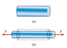
When a particular bar is loaded by tensile force, the axial lengthening is accompanied with lateral type of contraction (i.e. contraction which is normal to the direction of the applied load). The lateral strain which is induced at any point in a bar is always proportional to the axial strain at the same point if the material of component is linearly elastic. The ratio of these strains is a property of the material known as Poisson’s ratio. This dimensionless ratio, usually denoted by the Greek letter ν (nu), can be expressed by the equation

Here negative sign indicates opposite directions or signs for strains. ν is assumed same in Tension as well as Compression. Some values of ν are 0.1 for concrete, 0.5 for rubber and approx. 0 for cork.
Here fig.(a) represents bar before applying force P, fig.(b) represents bar after loading (Here Lateral strain is denoted by dotted lines).
We know that by using Hooke’s law i.e.
Stress  Strain

This constant of proportionality (E) is known as Modulus of Elasticity or Young’s Modulus. Numerically, Modulus of Elasticity is that value of tensile stress, which when applied to uniform bar will increase its length by unit value of strain. As the strain is dimensionless, the units of Young’s Modulus are same as that of Stress, i.e. Pascal (Pa) or N/m2. This Young’s Modulus is also the slope of stress-strain curve in elastic region that will be discussed later.
Some of the values of E are, Steel = 200-220 GPa, Wrought Iron = 190-200 GPa, Aluminium = 60-80 GPa.


Where C = Constant of proportionality known as Modulus of Rigidity or shear modulus.
When a body is subjected to three stresses, which are mutually perpendicular, of equal intensity, the ratio of direct stress to the volumetric strain produced, is known as Bulk Modulus. It is denoted by K.
Mathematically,

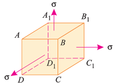
Relation between Young’s Modulus and Bulk Modulus:
Here,  = Tensile stresses
 = length of cube
E = Young’s modulus of the cube material.
Now, we will consider deformation of any one particular side (say AB). Here, this deformation will be caused by,
The tensile stress mentioned above will result in longitudinal strain of  /E. The compressive stresses will result in lateral strain of [ν*(
 /E)], where ν = Poisson’s ratio.
Thus, the total strain produced is given as,


Now, the volume of cube is  3, thus
 3
3
Differentiating with respect to  , we get,


Now, replacing the value of  mentioned above.


Now, replacing  3 by
3 by  ,
,

Replacing  by
by  , we get,


The above equation gives relation between Young’s Modulus (E), and Bulk Modulus (K).
Relation between Young’s Modulus and Modulus of Rigidity:
Consider a cube of length  subjected to a shear stress of
  , as shown in the above fig.(a). Due to these stresses, diagonal BD will be elongated and diagonal AC will be shortened, to BD1 and AC1 respectively.
This shear stress will cause shear strain ( , shown in fig.


Now, we found that the linear strain on BD is half of the shear strain and is tensile in nature. Similarly, it can be proved that linear strain on AC is half of shear strain and is compressive in nature.
Now, linear strain in diagonal BD is

Where  = shear stress and C = Modulus of rigidity.
We know that, the effect of the shear stresses will be the tensile stress on diagonal BD and compressive stress on diagonal AC. The tensile strain on diagonal BD by tensile stress on diagonal BD is given by,

The tensile strain on diagonal BD by compressive stress on diagonal AC is given by,

The combined effect of the above-mentioned strains is given as,

Therefore, combining the strain obtained and shear strain obtained we get,


The above equation gives relation between Young’s Modulus E and Modulus of Rigidity (C).
Stress-Strain curve for Ductile Materials:
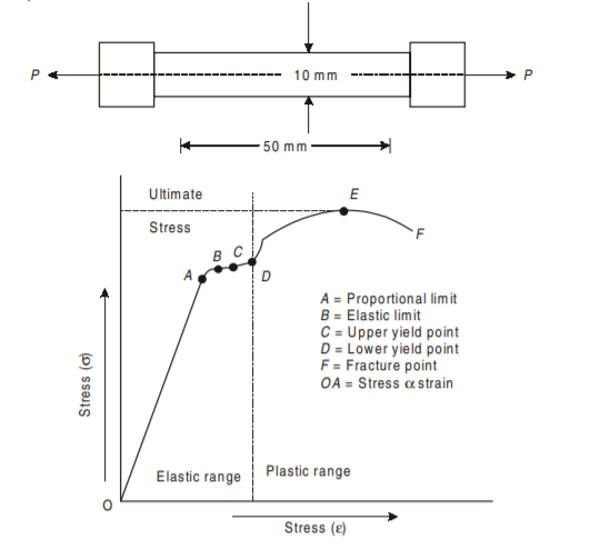
2. Elastic Limit. Point B indicates the elastic limit stage. Between points A and B although the strain increases slightly more than the stress, yet the material is elastic i.e., on the removal of load, the material will regain its original shape and size. If the material is stressed beyond point B, the deformation will take place. Points C and D are upper and lower yield points respectively. Between points B and C, the strain increases more rapidly than the stress. At this point C the dial, which gives the reading of the load suddenly becomes stationary for few seconds to point D. Beyond point D, the load again starts increasing but the elongation increases at faster rate than load up to point E. Hence E indicates maximum or ultimate stress point. The bar of specimen begins to form a local neck. Point F is the breaking point. The extension remains continuous even with lesser load and fracture occurs at point F. The stress corresponding to the peak load is called ultimate tensile stress or ultimate tensile strength or tensile strength. The stress corresponding to the load when the specimen ruptures is called rupture strength.
3. Yield Point. The yield point is the point at which considerable elongation of the test specimen occurs with no noticeable increase in the tensile load (Stress). This phenomenon is known as yielding of the material and point C is called the yield point. The corresponding stress is known as the yield stress. In this region (i.e., between points C and D) the material becomes perfectly plastic, which means that it deforms without an increase in the applied load. The elongation of specimen in the perfectly plastic region is typically 10 to 15 times the elongation that occurs up to the proportional limit.
4. Ultimate Stress. The ratio of maximum load to the original cross-sectional area of a bar is called ultimate stress.

5. Percentage Elongation. The ratio of percentage increase in gauge length to the original gauge length is called the percentage elongation.

where,
 = original gauge length
 = final gauge length after fracture
6. Working Stress. The greatest stress that is induced in a section is called the working stress.

7. Factor of Safety. Factor of Safety can be defined as the ratio of Ultimate stress to the Working or generated stress.

The factor of safety is also known as factor of ignorance. It is decided by experience and depends upon the number of factors such as nature of loading, degree of safety, degree of economy required, permanency of design, material used, etc. For cast iron, concrete, wood etc. the value of factor of safety may be taken as 4 to 6.
8. Breaking Stress. The ratio of load at the breaking or fracture point and original cross-sectional area of a material is called breaking stress or rupture stress.

9. Rupture Strength
The rupture strength is the stress at failure. The elongation of the bar beyond
ultimate point is accompanied by a decrease in the load and fracture or breaking lastly occurs at a point shown as F. The rupture stress at F is less than the ultimate stress at E (as shown by curve EF) is somewhat misleading. When a test specimen is stretched, lateral contraction occurs. The resulting decrease in cross-sectional area is too small to have a noticeable effect on the calculated values of the stresses up to the yielding region, but beyond that point the reduction in area begins to alter the shape of the curve. When the stress-strain graph approaches ultimate stress, the reduction in cross-sectional area of the specimen is clearly visible and then the necking of the section takes place. If the actual cross-sectional area of the narrowest part of the neck is used to calculate the stress, the true stress-strain curve may be obtained.
10. Percentage reduction in area. Ratio of the percentage decrease in cross-sectional area to the original cross-sectional area is called the percentage reduction in area after rupture.

Where  = Original cross-sectional area,
  = final cross-sectional area.
11. Nominal Stress and True Stress. When the initial area of the specimen (based on original diameter or nominal diameter) is used in the calculation, the stress is called the nominal stress (or conventional stress or engineering stress). A more accurate value of the axial stress, called the true stress, can be determined by using the actual area of the bar at the cross-section where failure occurs. True stress is always larger than nominal stress because actual area during rupture is always less than the normal area of the section.
12. True Strain & Nominal strain. If the initial gauge length is used in the calculation, then the nominal strain is obtained. Since the distance between the gauge marks increases as the tensile load is applied, we can calculate the true strain (or natural strain) at any value of the load by using the actual distance between the gauge marks. In tension true strain is always smaller than the nominal strain. The conventional stress strain curve OABCDEF, which is based upon the original cross-sectional area of the specimen and is easy to determine, provides satisfactory information for use in engineering design.
Stress-Strain Curve for Brittle Materials:
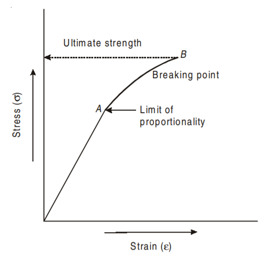
Brittle materials are those which show very little deformation before fracture. Brittle materials like concrete, aluminium and cast iron have very low proportional limit and do not show the yield point. For brittle materials the stress-strain graph is continuous curve from the beginning itself as shown in fig. below. The breaking stress at point B is well defined. The brittle material has relatively small tensile strain upto the breaking point.

Factor of Safety can be defined as the ratio of Ultimate stress to the Working type of stress.

The factor of safety is also known as factor of ignorance. It is decided by experience and depends upon the number of factors such as nature of loading, degree of safety, degree of economy required, permanency of design, material used, etc. For cast iron, concrete, wood etc. the value of factor of safety may be taken as 4 to 6.
Determinate Beam:
Sometimes a bar made up of various lengths having dissimilar cross-sectional areas (below fig.) are used. In such cases, the stresses, strains and hence changes in lengths for each section are worked out separately as usual. The total changes in length is equal to the sum of changes of all the individual lengths. It may be noted that each section is subjected to the same external axial pull or push.


Sometimes a body is subjected to a number of forces acting on its outer edges as well as at some other sections, along the length of the body. In such a case, we split or distribute the forces and then consider their effect on each section. The resulting deformation, of the body, is equal to the algebraic sum of the deformations of individual sections. Such a principle, that is used to find the resultant deformation, is called principle of superposition. The relation is given below as:

Where P is the force which acts on 1st section
 is 1st section length
 are section 2 corresponding values
Indeterminate Beam:
When a system comprises two or more members of different materials, the forces in various members cannot be determined by the principle of statics alone. Such systems are called as Statically indeterminate system. In such systems, additional equations are required to supplement the equations of statics to determine the unknown forces. This is explained below with an example of composite section.
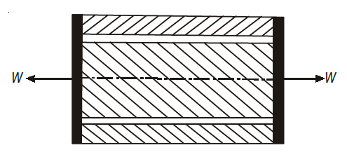
A composite section means a section made of different metals connected rigidly at both ends together. It is also called a compound section. Suppose, a composite section consists of a central copper rod, loosely surrounded by a brass tube and their both ends firmly connected together, as shown in Fig. Here the total applied load is distributed within the members of composite section. Let the bar be subjected to an axial tensile (or compressive) load W as shown.
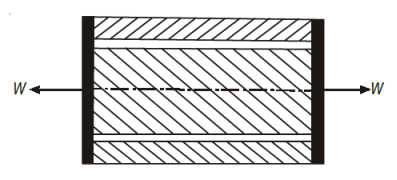
Let Ab = cross-sectional area of the brass tube
Ac = cross-sectional area of the copper rod
Eb = Young’s modulus for brass
Ec = Young’s modulus for copper
l = their common length.
and  and
and  are the stresses induced in brass and copper respectively.
Since both the rod and the tube are held together at the ends, their elongation and hence the strains will be the same, but as their Young’s moduli have different values, so the stress induced in each will also be different. Since strain in both is the same,


where  = load shared by brass
 = load shared by copper
The elongation of plain and composite bars can be explained with the example of a rectangular cross-section as follows:
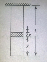
Consider a bar hanging freely under its own weight as shown in fig. Consider a small length  of the bar at a distance x from the free end.
Let, A = area of cross-section of the bar, L = Length of the bar, w = weight per unit volume of the bar, W = weight of the whole bar = wAL, Wx = weight of the bar below the small section = wAx.


Thus, the deformation of the bar under its own weight is equal to half the deformation due to a direct load equal to the weight of the body applied at lower end for rectangular section. For composite members, extension can be determined as combined effect of the materials present in the section.
The bars which are subjected to concentrated load may be solved using the equations like flexure formula, which are discussed in the next section of Bending stresses in beams.
Temperature Stresses in Plain Members
When the temperature of a body is raised or lowered, there is corresponding increase or decrease in its dimensions and if this change in dimensions due to the temperature variation is prevented by application of external forces, the body develops stress in it, which is called the temperature stress ; and the corresponding strain is called the temperature strain. The extension due to rise of temperature, can be checked or suppressed by compressive forces; thereby producing compressive stresses in the body or vice versa. Suppose, a bar of uniform section and of length l is heated through temperature T. The length of the bar will increases depending upon its co-efficient of linear expansion which is defined as the increase in length per unit rise of temperature per unit original length and is generally denoted by the Greek letter  (alpha).
Extension of the bar when free to expand = αTl.
Now suppose, this extension due to increase of temperature is prevented by either fixing the bar at its ends or by the application of external compressive forces.


Which is compressive in nature.
Temperature stress = Temperature strain × E = αTE (compressive)
Conversely, the contraction caused by lowering of the temperature can be checked by applying tensile forces to the bar resulting in temperature stress of tensile nature in it.
Temperature Stress in Composite Members
Consider a composite bar comprising of two metals (1) and (2), as show in Fig. Suppose x–x be the initial level and y–y be the final level after the rise in temperature t. If both bars were free to expand, the extension of material (1) would be lα1t and that of material (2) would be lα2t on the assumption (α2 > α1). Since both materials are rigidly connected at the ends, material (1) is forced to extend a distance x´1 and material (2) is forced to compress a distance x´2 as shown in figure. Stresses in materials will be induced only due to these forced changes x´1 and x´2.
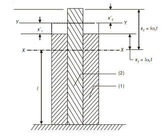
From the figure it will be seen that:


Also, since no external force is applied to the composite bar,
Tensile force in material (1) = Compressive force in material (2)
Thus, using the above equations, the desired values can be determined.
In addition to rise in temperature t, if the bar is subjected to an external load P (Fig. below) material (2) will suffer further compression and exerts an additional upward reaction P2, whereas material (1) will be relieved of its forced extension x´1 and help P in downward by force P1.
For equilibrium P + P1 = P2
α1 α1 – α2α2 = P
from the above equations, value of α1 and α2 can be found out.