Unit 2
Shear Force and Bending Moments Diagrams
Shear Force (briefly written as SF) at the cross-section is unbalanced net vertical force on either side of a section.
The bending moment (B.M) may be defined as the algebraic addition of all the moments created by the forces, either to the left or right of the cross-section.
The SFD and BMD are used to analyze the beam upon application of various types of forces.
Beam: A beam is a horizontal structural member subjected generally to vertical loads.
Types of Beams:
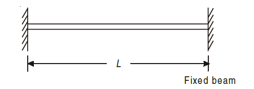
A beam whose both ends are rigidly fixed is called fixed (builtin) beam.
Simply supported beams are those which have supports at both the ends. Generally, the beam is supported with a hinge or pin support at one end and a roller support at the other.
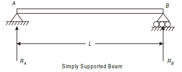
The roller support does not prevent translation in horizontal directions but it prevent translation in the vertical direction.
An overhanging beam is supported with either one or both ends extending beyond the supports. The extended portion of the beam acts like a cantilever.
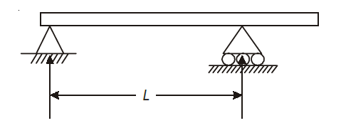
Fig. One end Overhanging

Fig. Both ends Overhanging
Cantilever beams are those whose one end is fixed and other is free. There is restriction for translation or rotation at the fixed end, thus both moment and force exist at the fixed end.
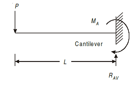
A beam supported at more than two points is called continuous beam.
If the external support reaction can be found directly from the equation of static equilibrium, then these are statically determinate beams. Examples, simply supported beam, overhanging beam and cantilever beams.
Types of Supports:
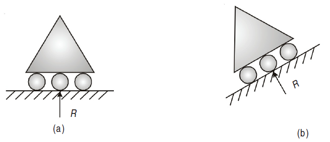
Roller support has only one reaction which is always normal to the contact surface.
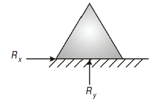
Hinged support has restriction to movement in x and y direction, therefore, it has two reactions Rx and Ry.
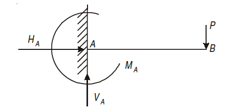
Fixed support has restriction to move in x and y direction as well as rotation about that point. It has three reaction i.e., VA, HA, MA.
Types of loading:
A load which is acted at a point is called as point load.

A load which is uniformly spread over the beam is called as uniformly distributed load. (U.D.L).
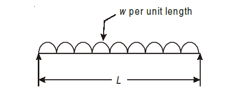
Equivalent point load = Intensity of load × Length = w × L
Act at C.G. of loading i.e. (L / 2).
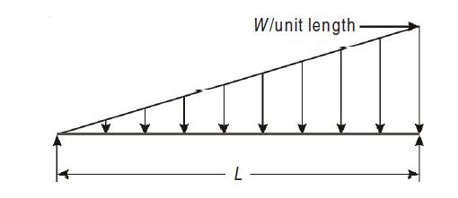
The intensity of loading increases or decreases at a constant rate is called as uniformly varying load (U.V.L) or triangular loading.
Equivalent point load = Intensity of load × Length

Act at C.G. of loading i.e., at 2L/3 or L/3.
Shear force is taken as positive if it tends to move the left portion upward with respect to right portion and vice-versa. A better rule of sign, which is easier to remember is to give a positive sign to those forces acting upward on the left portion.

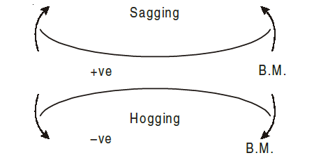
Bending moment is taken positive if it tends to sag (concave form) the beam, and if it is negative it tends to hog (convex shape)
Rules for Drawing SFD and BMD:
Below are some of the rules for drawing the SFD and BMD for various loading conditions:
1. Shear force suddenly changes if the force applied is a point load (i.e., the shear force line is vertical). But the bending moment remains the same.
2. If there is absence of any type of load or forces between two points, then the shear force remains constant (i.e., shear force line is horizontal). But the linearity is followed for Bending Moment (i.e., bending moment line is an inclined straight line).
3. If there is a uniformly distributed load between two points, then the shear force changes linearly (i.e., shear force line is an inclined straight line). But the bending moment changes according to the parabolic law. (i.e., bending moment line will be a parabola).
4. If there is a uniformly varying load between two points then the shear force changes according to the parabolic law (i.e., shear force line will be a parabola). But, Cubic law is followed for the Bending Moment.
example. Construct shear force and bending moment diagrams for the cantilever as loaded in Fig.


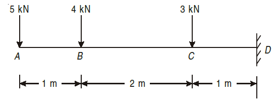
Using the sign conventions mentioned above, we start by considering the left most force of 5kN.When we go to the right of A, point load at A will be negative (section shown by black dotted line). As there are no loads between A and B, the same will remain till left of B.
FA = – 5 kN.....(section denoted by black dotted line)
When we go to the right of point B, we will consider the point load acting at point B, section shown by blue dotted line.
FB = – (5 + 4)
= – 9 kN....blue dotted line
9 kN will continue to the left of point C, but when we go the right of point C, we will consider the point load at point C, the section shown by red dotted line.
FC = – (9 + 3)
= – 12 kN....
section shown by red dotted line
FD = – 12 kN
the value will continue to the left of D.
Thus, the SFD diagram will be as shown below,

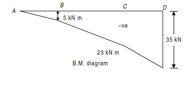
For solving Bending Moment Diagram, we start from leftmost side of Beam i.e. from point A. Here, BM at starting end-point is taken as 0 for point load.
MA = 0
At point B, the moment will be force of 5kN multiplied by distance AB, i.e.1m
MB = – (5 × 1)
= – 5 kN m.. Hogging moment
Now, a slant line is to be drawn between AB.
Now, at point C, again we will need to consider the addition of bending moments by Forces at A and B, thus,
Mc = – (5 × 3) + (– 4 × 2)
= – 23 kN m (Hogging moment hence negative)
Again, a slant line is drawn between BC.
Now, for point D, we will need to consider the bending moments due to forces at A, B and C.
MD = – (5 * 4) + (– 4 * 3) + ((– 3) * 1)
= – 35kNm
Now, as bending moment is 0, hence the line will be vertical as stated in the rules at point D.
The BMD will be as follows,
Let us consider the solving of SFD and BMD for statically determinate beam due to uniformly distributed load using the example below.

For solving, we will use the same sign conventions and methodology, but just the change is that, UDL (uniformly distributed load) is calculated by multiplying the value mentioned in kN/m by the total length of UDL.
Lets start from extreme left.
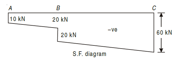
FA = – 10 kN
Now, it will not be constant till B as there is UDL in between, hence to the left of point B, the forces will be sum of UDL of length AB and 10kN.
i.e. -10-(10kN/m)*(1m)=-20kN
Now, when we go to the right of point B, we will consider point load at B.
Here the complete force acting is given as:
FB = –(10+(10 * 1) + 20)= – 40kN
As we go to next point, i.e. C, it will include all the forces till point B, and UDL of length between the two points i.e. BC, i.e.
Fc = – (10 + 20 + 10 × 3) = – 60 kN
The same amount of reaction will be provided (60kN) by fixed support.
Hence, SFD will be as follows:
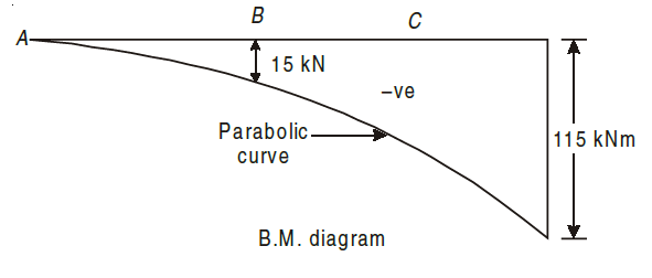
For BMD, we will start from extreme left.
MA = 0
For bending moment at point B, we need to consider the moment by force at A and UDL which is converted to point load acting at midpoint of AB i.e. at 0.5m from B.
Hence,
MB = – (10 × 1 + 10 × 1 × 0.5) = –15 kN m
Similarly, for BM at point C, we need to consider point loads at A, B and UDL between AC, acting at midpoint of AC (1.5m from C)
MC = – (10 × 3 + 20 × 2 +10 × 3 × 1.5)
= – (30 + 40 + 45) = –115 kN m
Here, all the moments are negative as the action of moments is Hogging of beam.
The BMD is as follows:
Let us consider the solving of SFD and BMD for statically determinate beam due to uniformly varying load using the example below.

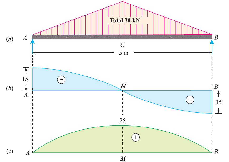
From the symmetry of the diagram, RA = RB =30/2=15kN
Starting from extreme right, we know,
FA = 15kN
Now, when we go to the point C, the forces will be sum of reaction A and UVL of length AC which is half of AB. Thus, UVL will also be half i.e. 15kN.
FC = 15-15=0kN
Then FB = 0-15=-15kN
For BMD, at endpoints A and B, it will be zero and will be maximum at centre, given by (W*l)/6
MC = (30*5)/6 = 25kN m
Thus the SFD and BMD diagrams will be as follows:
Let us consider the solving of SFD and BMD for statically determinate beam under couple and combined loading using the example below.
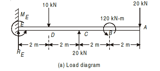
We do not need to consider the values of Couple while calculating SFD, thus for calculating SFD, we will use the same methodology and sign conventions mentioned above.
(1) Find Reaction as
y = 0 ; ( + ve)
RE –10 – 20 + 20 = 0
RE = 10 kN
ME = 0; ( + ve)
20 × 8 + 10 × 2 – 20 × 4 – 120 = 0
ME = 20 kN-m, Anticlockwise
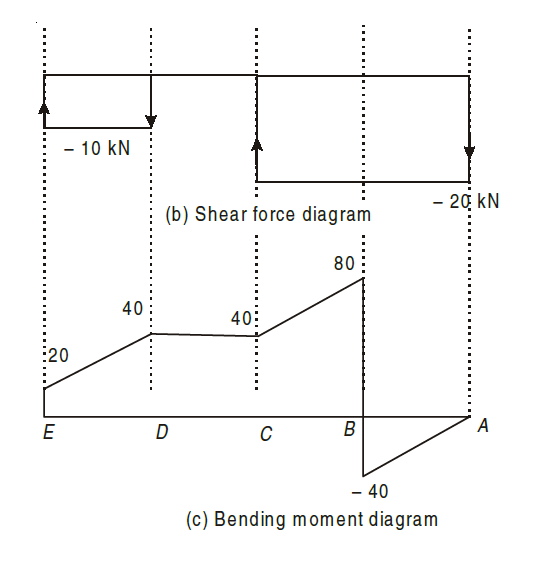
(2) Shear Force Portion AC
S.F. = – 20 kN, constant
Portion, CD S.F. = – 20 + 20 = 0;
Portion DE S.F. = –20 +20 – 10 = – 10 kN (Constant)
(3) Bending Moment
Portion AB: (0 < x < 2)
BM = – 20 x—varies linearly with x
at x = 0, BMA = 0.
at x = 2 m, BMB = – 40 kN-m
Portion BC : (0 < x < 2)
Take section between B and C, at a distance x from B.
BM = – 20*(2+x)+120
at x = 0, BMB = 80kNm
at x = 2, BMC = – 20*(4)+120
BMC = 40kNm
For part CD: Taking section in between point C and D,
i.e. at a distance of x from point C.
BM = – 20 (4 + x) + 120 + 20 (x)
at x = 0, BMC = – 80 + 120 = + 40 kNm
at x = 2 m, BMD = – 120 + 120 + 40 = + 40 kNm
Portion DE: (0 < x < 2)
Take section between D and E, at a distance x from D.
BM = – 20 (6 + x) + 120 + 20 (2 + x) – 10 (x)
at x = 0, BMD = – 120 + 120 + 40 – 0 = + 40 kNm
at x = 2 m, BME = – 160 + 120 + 80 – 20 = + 20 kNm
Consider a small length  x cut out from loaded beam at distance x from fixed origin O as shown in fig.

Let, w = mean ate of loading on the length  .
.
F = shea force at section x
F +  = shear force at section x +
M = bending moment at section x
M +  = bending moment at section x +
Total load on the small length = w* acting approximately through the centre,
Thus, for equilibrium of length  , equating vertical forces,
F = w + (F +
 )
)

Thus, the rate of change of shear force (or slope of shear force curve) is equal to the intensity of loading.
Taking moment about C,

Neglecting the product and squares of small quantities,

Shear force may be said to be rate of change of bending moment.
The following relations between loading, shear force and bending moment at a point or between any two sections of a beam are used
1. Shear force suddenly change on application of point load (i.e., the shear force line is vertical). But the bending moment remains the same.
2. Shear force line is horizontal if no load is present. Bending moment line is an inclined straight line.
3. If there is a uniformly distributed load between two points, then the shear force changes linearly (i.e., shear force line is an inclined straight line). But the bending moment changes according to the parabolic law. (i.e., bending moment line will be a parabola).
4. If there is a uniformly varying load between two points then the shear force changes according to the parabolic law (i.e., shear force line will be a parabola). Bending moment varies following the Cubic law for drawing.
According to the relations obtained above, we know that

i.e. Shear force may be said to be the rate of change in the bending moment.
Thus, if at a point  = 0, i.e. shear force value is zero according to the above equation, it will be called point of zero shear force. Also, if
  , then the value of M will be maximum, thus called as maximum bending moment. This mostly takes place when the shear force diagram moves from positive to negative or vice versa. Thus, it crosses the base line at a point where it becomes zero, and at that point in bending moment diagram we achieve maximum value.
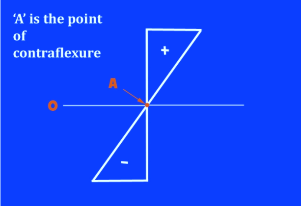
In a beam that's flexing (or bending), the purpose where there's zero bending moment is named as the point of contraflexure. At that time , the direction of bending changes its sign from positive to negative or from negative to positive.
For this alteration to happen, it must undergo zero – the point of contraflexure. On Bending moment diagram, it is at the point where the value of bending moment is momentarily zero.
It can also be explained using an example of moving automobile. If it is going forward at 20m/s and if it needs to go reverse, it will need to momentarily stop and then go reverse, similarly when the value of bending moment becomes zero, is point of contraflexure.
When we consider a member under load, the point of zero bending moment would appear to suggest no reinforcement would be required. However, omitting reinforcement at that point is taken into account inadvisable as, in real life, it may be difficult to locate point of contraflexure, with high accuracy.
