Unit 3
Stresses, Slope & Deflection on Beams
A beam is a structural member on which external loads act at right angles to its longitudinal axis. When a beam is subjected to a constant bending moment, then it is said to be in a state of pure bending or simple bending.
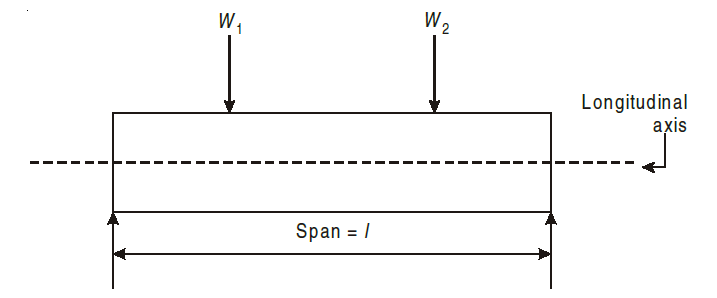
The external bending moment caused by the forces at a section results in bending the beam while internal stresses resist this external bending. The resistance offered by the internal stresses to the bending is called bending stress and the relevant theory is called the theory of simple bending.
Derivation of Bending Stresses
Consider a portion of pure beam subjected to pure bending.
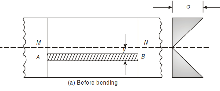
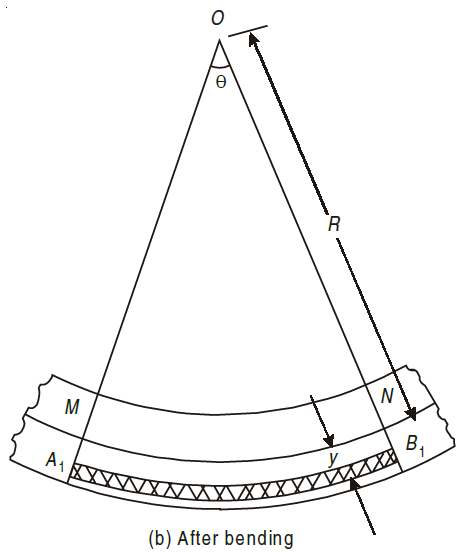
A fibre such as AB at a distance y from the neutral axis as shown in Fig. (b) is chosen. After bending it has elongated and is shown by A1B1 (Fig. b). Let R be the radius of the neutral surface after bending making an angle θ at the point O.
MN = R θ
A1B1 = (R + y) θ


Stress intensity in any form is proportional to the distance of the fibre from the neural axis.
Consider small length dx of a simply supported beam subjected to a bending moment M. Now, let us consider any two section viz. AB and CD that will be perpendicular to the axis of beam RS. Due to action of bending moment, the beam as a whole will bend as shown in Fig.(b).
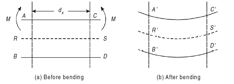
As seen in fig, the top layer ‘AC’ has gone into compression and decreased to A´C´. Layer RS has suffered no change in length, though bent to R´S´. Lower most layer BD has been stretched to B´ D´. Hence layers above RS have been compressed and those below RS have been stretched. This layer RS, neither goes into tension nor compression is also called as Neutral plane or Neutral layer.
The above-mentioned theory is also known as “Theory of Bending”.
The assumptions made in the theory of simple bending are explained as following.
1. The material of the beam is perfectly homogenous.
2. The beam material should be stressed within the material’s elastic limit.
3. Each layer of the beam can expand or contract, without depending on any layer above or below it.
4. The transverse sections which wave plane before bending remain plane after bending also.
5. The value of E (Young’s Modulus of Elasticity) is same in tension and compression.
6. The beam is in equilibrium i.e., there is no resultant pull or push in the beam section.
Moment of Resistance:
We know that on one side of the neutral axis there are tensile type of stresses while on the other, there are compressive type of stresses. Couple is formed by these types of stresses, whose moment should be equal to external moment created(M). The moment of this type of couple, which opposes the external bending moment, is known as the moment of resistance.
Now, let’s consider a section or part of the beam shown in below. Let the neutral axis of the section denoted by NA. Now consider a small layer PQ of the beam section at a distance y from the neutral axis as shown in Fig. below.
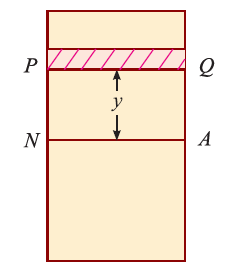
Let δ A = Area of the layer PQ.


Thus, the total stress is given by,

Moment of this total stress about neutral axis is given by,


Here the algebraic sum of all the moments present about the neutral axis should be equal to M. Therefore


The expression  represents the moment of inertia of area of the complete section about the neutral axis. Therefore,

Where I= moment of inertia,
We know that,

Therefore,

The above equation is also known as Bernoulli-Euler bending equation or Flexural Formula.
Moment of Inertia of a Rectangular cross-section:
Consider a rectangular section ABCD as shown in Fig. below.
Let b be the width of the section and
d be the depth of the section below.
Now consider a small section PQ of thickness dy which is parallel to X-X axis and is at a distance of y from it as shown in the figure below.
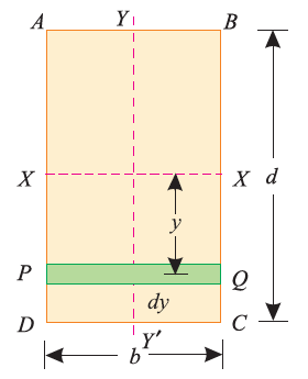

We know that the moment of inertia of the section about X-X axis = Area*y2
= (b*dy)* y2
= b*y2*dy
Now moment of inertia of the whole section may be found out by integrating the above equation for the whole length of the lamina i.e. from  to
to  .
.


Moment of Inertia of a Circular cross-section:
Consider a circle ABCD of radius (r) with centre O and X-X' and Y-Y' be two axes of reference through O as shown in Fig. Now let us consider an elementary circular section of ring of radius x and thickness dx.
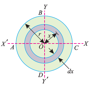
Therefore, area of the ring shown above, da = 2πx*dx
and moment of inertia of ring, about X-X axis or Y-Y axis is


Now moment of inertia of the whole circular section, about the central axis Izz, is calculated by integrating the above equation for the complete radius of the circle i.e., from 0 to r.


Where d=2r,
We know from the Theorem of Perpendicular Axis that
Ixx + Iyy = Izz
i.e. Ixx = Iyy = Izz/2
Moment of Inertia of a Hollow Circular cross-section:
Consider a hollow circular section as shown in Fig., whose moment of inertia is required to be found out.
Let D be the diameter of the main circle (outer circle), and
d be the diameter of the cut-out circle (inner circle).
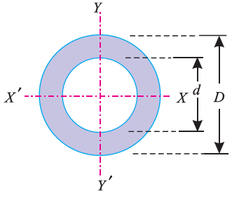
We know that the moment of inertia of the main circle about X-X axis is 

and moment of inertia of the cut-out or inner circle about X-X axis is 

∴ Moment of inertia of the hollow circular section in diagram above, about X-X axis can be found out as,
Ixx = Moment of inertia of main circle – Moment of inertia of cut out circle


Moment of Inertia of a Composite Section (I and T section):
The moment of inertia of a composite section may be found out by the following steps:
1. First of all, we need to divide the given section into plane areas like rectangular or triangular or circular etc., and then we need to find the centre of gravity of the section.
2. Find the moments of inertia of these areas about their respective centres of gravity.
3. Now transfer these moments of inertia about the required axis (AB) by the Theorem of Parallel Axis, i.e.,
IAB = IG + ah2
where IG = Moment of inertia of a section about its centre of gravity and parallel to the axis, a is the area of the section, h is the distance between the axis considered and the centre of gravity of the complete section.
4. The moments of inertia of the given section may now be obtained by the algebraic sum of the moment of inertia about the required axis.
Bending Stresses in the sections:
Bending Stresses in Rectangular section:
We know the bending equation as:

Here,

The ratio,  is known as section modulus, represented by Z.

Thus, the above-mentioned equation is used for finding the bending stresses developed ( ), Bending Moments (M) generated and section modulus of various sections.
We have seen in the previous articles that there is no stress at the neutral axis. In a simply supported beam, there is always a tensile type of stress below the neutral axis and a compressive stress above it. (In a cantilever, there is a compressive type of stress below neutral axis and a tensile stress above the neutral axis.) We know that the stress at any point is directly proportional to its distance from neutral axis. If we plot the stresses in a simply supported beam section, we shall get a figure as shown below.
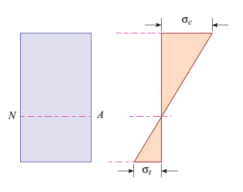
The maximum stress (either compressive or tensile) takes place at the outermost layer. Or in other words, while obtaining maximum bending stress at a section, the value of y is taken as maximum.
Previously we discussed the theory of simple bending. In this theory, we assumed that no shear force is acting on the section. But in the actual work conditions when a beam is loaded, the shear force at a particular section always cause an effect, along with the bending moment. It has been observed that the effect of shearing stress, as compared to the bending stress, is quite negligible, and is not of much importance. But, sometimes, the shearing stress at a section assumes much importance in the design criterion.
Consider a small portion ABCD of length dx of a beam with bending moment
varying from M to (M + dM) due to uniformly distributed load (U.D.L.) over its length dx. The distribution of compressive stresses due to bending moment is shown in Fig. below.
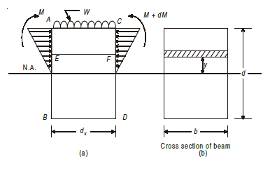
Let, M = Bending moment at AB
M + dM = B.M. at CD
F = Shear force at AB
F + dF = S.F. at CD
Consider elemental strip EF at a distance y from neutral axis (Fig.)
Let,
σ = Bending stress across AB at a distance y from neutral axis
σ + dσ = Bending stress across CD
I = Moment of inertia
By using flexure formula,

On face AB,

And on face CD,

Force acting across AB; FAB = stress on AB × Area

Similarly, force acting across CD;

Net unbalanced force on the strip;
dF = FCD – FAB


The total unbalanced force F above neutral axis can be found out by
integrating from 0 to d/2.


But
 = First moment of area under consideration from neutral axis
Which is also given by,

Therefore,

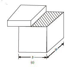
This unbalanced force is balanced by a shearing stress τ acting along the
length dx and width b.


But,

Putting in main equation, we get,

where,
S = Shear force at the section under consideration
A = Area above or below the layer under consideration
 = Distance of centroid of area under consideration from neutral
axis
b = Width of the layer under consideration
I = Moment of Inertia of the section.
Shear stress distribution along Circular cross-section:
Consider a circular section of diameter d as shown in Fig.(a).
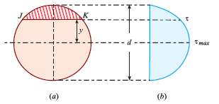
We know that the shear stress on a section JK at a distance y from the neutral axis as shown in fig. above,

We know that in a circular section, width of the strip JK is given by,
 …i
…i
And, area of the shaded strip is given by,

Moment of this area about neutral axis is given by,

Now moment of the whole shaded area about the neutral axis may be calculated by doing the integration of the above equation between limits of y and r,

 …ii
…ii
We know that,


Differentiating, we get,


Putting y*dy in equation ii. we get,


We know that when y = y, width b = b and when y = r, width b = 0. Therefore, the limits of integration may be changed from y to r, from b to zero in equation,


Now, substituting these values in main equation, we get,


Substituting value of b obtained we get,

Thus, we again see that τ increases as y decreases. At a point, where y = r, τ = 0, = 0 and where y is zero, τ is maximum. We also see that the variation of τ with respect to y is a parabolic curve. We see that at neutral axis τ is maximum.
Substituting y=0 and I =  , we get,

Shear stress distribution diagram along Rectangular cross-section:
Consider a beam of rectangular section ABCD of width and depth as shown in Fig. (a). We know that the shear stress that is created on a section JK of the beam, at a distance of y from the neutral axis,

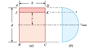
where F = Shear force at the section,
A = Area of section above y (i.e., shaded area AJKD),
y = Distance of the shaded area from the neutral axis,
 = Moment of the shaded area about the neutral axis,
I = Moment of inertia of the whole section about its neutral axis, and
b = Width of the section.
Area of the shaded portion AJKD is given by,


Substituting these values in main equation, we get,

We see, from the above equation, that τ increase as y decreases. At a point, where y = d/2, τ = 0; and where y is zero, τ is maximum. We also see that the variation of τ with respect to y is a parabola. At neutral axis, the value of τ is maximum. Thus, substituting y = 0 and I =  , we get,

Shear stress distribution diagram along I cross-section:
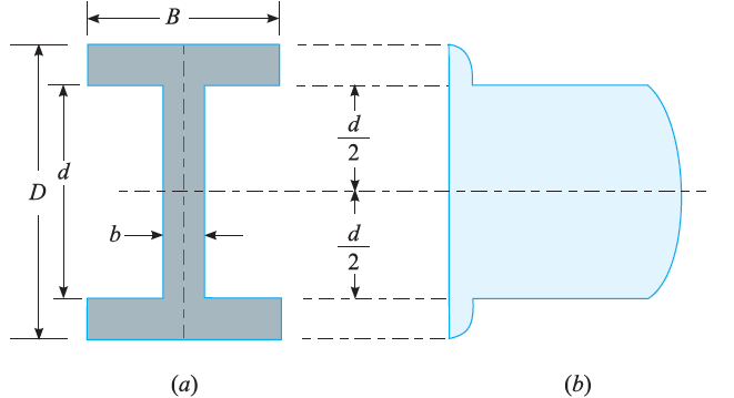
Consider a beam of an I-section as shown in Fig. (a)
Let B = Overall width of the section,
D = Overall depth of the section,
d = Depth of the web, and
b = Thickness of the web.
We know that the shear stress on a layer JK at a distance y from the neutral axis is given by,

Substituting all the values which are to be calculated by the procedure mentioned previously, we get,


Shear stress distribution diagram along T cross-section:
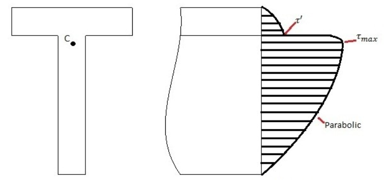
The calculation of the shear stress and all the parameters can be calculated in a similar way as mentioned earlier.
Whenever a beam is loaded, it deflects from its original position. The amount, by which a beam deflects, depends upon its cross-section and bending moment. The beam should needs to be enough to resist bending moment and shear force. The beam should also be stiff enough to resist its deflection. The beam should be stiff enough not to deflect more than permissible limit.

The curve in which the beam bends due to loading is called elastic curve.
The vertical distance (y) at any point in a beam between elastic curve and original axis of beam is called deflection at that point. Deflection is denoted by y, Δ or δ and is zero at the supports. Slope at any point is defined as the angle in Radian between the tangent to the elastic curve at that point and the original axis of the beam. It is denoted by θ or 
Consider a small portion PQ of a beam, bent into an arc (As shown in Fig.)
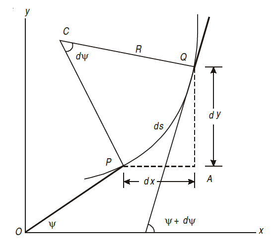
Let,
ds = Length of beam PQ
R = Radius of the arc, into which the beam has been bent
C = Centre of the arc
ds = Length of the beam PQ
R = Radius of the arc, into which the beam has been bent.
ψ = Angle, which the tangent at P makes with x – x axis, and
ψ + dψ = Angle which the tangent at θ makes with x – x axis
From the geometry of figure, we get,
∠PCQ = dψ
ds = R *dψ
considering ds = dx

We know that if x and y be the co-ordinates of point P, then

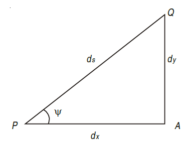
As  is small, tan
 =
=
Differentiating, we get,

We know that,


Substituting the value of (1/R), we get,

i.e.
The above-mentioned equation is known as Differential equation for bending, which also gives the relation between slope, deflection and radius of curvature.
The Macaulay’s method is explained as following.
1. This method is similar to double integration method.
2. It is used to find the slope and deflection at any point on the beam.
3. In this method, bending moment at any section is expressed in systematic
order.
4. The section x is to be taken in the last portion of the beam.
5. In this method, bending moment of each force or U.D.L. is separated by a
compartment of lines.
6. Integrating bending moment equation, we will get slope equation.
7. Again integrating slope equation, we will get deflection equation.
For example, consider a beam subjected to loading as shown in Fig. below.
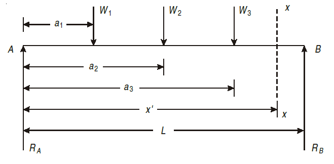
Step I. Determine the support reactions.
Step II. Consider a section x – x at a distance x covering all the loads from
left end of the beam.
Step III. Take moment of all forces about section x – x, considering sagging
B.M. as positive and hogging as negative.

Step IV. Use differential equation of deflection
i.e.


Step V. Integrating above equation, we get;

Step VI. Again, integrating above equation, we get

Step VII. The constant of integration c1 and c2 are calculated by applying
boundary conditions.
Step VIII. Substituting the value of constant, in equation obtained in step V gives general equation for slope and equation in step VI gives general equation for deflection.
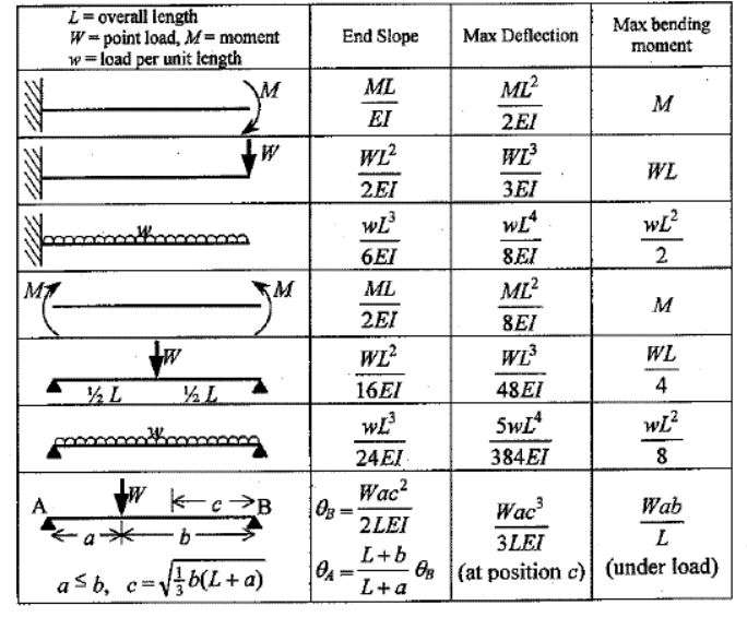
The slope and deflections can be found out using the formulae mentioned above and Macaulay’s Method. Some of the generalized formulae for slope and deflection of common beams is as shown in fig.
