Unit 4
Torsion, Buckling
“A member which is subjected to the couple which produce rotation about longitudinal axis is known as Twisting Moment or Torsion.”
When a force is applied tangentially to a cylindrical rod, at a certain radius, in the plane of its transverse cross-section, the rod is said to be subjected to twisting moment or torque. Torsion is also defined as the product of tangential force and the radius.
Figure below shows a circular shaft of length l and diameter d acted upon by a torque T.

The shear strain  of elements at radial distance r form the axis is constant for a particular value of T. The line OA thus twists to OB.
Let  be the angle of twist of a cross-section relative to another cross-section at a distance l apart. Then,


Now, tangential force on the element = 
Moment of tangential force on the element = 
Sum of moments for the whole shaft, 


But  is the polar moment of inertia of the shaft,
Thus


From (i) and (ii)

This equation is called as Torsion Equation.
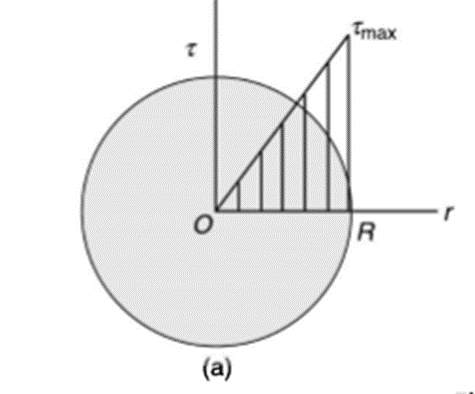
Torsion equation shows that for a given shaft, shear stress is proportional to the radius of shaft. Figure below shows a shear stress distribution in solid shaft of Radius R.
Polar moment of Inertia for solid circular shaft with diameter D is given as

Polar moment of Inertia for hollow circular shaft with outer diameter D and inner diameter d is given as

B. Polar Sectional Modulus
Polar sectional modulus is the ratio of sectional modulus to the maximum radius of shaft.
Mathematically,


For solid shaft,


For hollow shaft,


Now, we have from torsion equation,


The ability of shaft to resist the motion of twisting moment is called as strength of a shaft.
C. Torsional Stiffness
It is the torque required to produce unit angle of twist
It is given by,

D. Torsional Flexibility
It is the angle of twist produced by a unit torque applied


E. Torsional Rigidity
Torsional rigidity is the product of modulus of rigidity G and polar moment of inertia J
It is given by,

Stepped or composite shaft are either in series or parallel
Shafts in series:
When the two shafts are joined in series and a single torque is applied, both shafts are subjected to same torque.
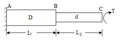


Also

The angle of twist for the shafts in series is the sum of the angle of twist of each shaft


Shaft in Parallel:
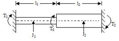
When the two shafts are joined in parallel, the torque applied to the composite shaft is the sum of the torques on the two shafts


The angle of twist in the shafts in parallel is same


Torque on strength basis
When the shaft is subjected to pure torsional moment, the torsional shear stress is given,


Therefore,

Torque on rigidity basis
From Torsion equation, we have,

Value of  in the above equation is in radian. Converting it into degrees

For solid shaft, we have

Therefore,


Where,  is in degree.
Torque found by strength basis and by rigidity basis is maximum torque.
Therefore,

Power transmission by shaft
It is the product of average torque and corresponding angle turned per unit duration of time.


Where, N is in rpm

The relation between average torque and maximum torque is

Where C is a constant,
Generally,

Torsional resilience is the strain energy stored within the elastic limit in a body (column or strut) subjected to torsion.
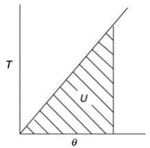
The total strain energy of shaft under the action of torque is the work done in twisting. Thus, for gradually applied torque T to the shaft of length  is
is

For solid shaft,


Therefore,


Torsional Resilience is nothing but the average strain Energy
Therefore,

Now,
Strain Energy per unit volume = 
As shear stress varies linearly. i.e. zero at axis and maximum at surface of shaft. Similarly strain energy also varies linearly. i.e. zero at axis and maximum at surface of shaft
Total strain energy is given by


Proof Resilience is defined as the maximum strain energy which can be stored in a body within a elastic limit is called as proof resilience.
In this case,

Consider a thin-walled closed tube acted upon by a torque T in a traverse plane as shown in figure.
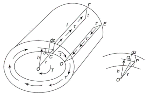
It may be assumed that the shear stress at a point across the thickness of the tube wall is constant.
Let  be the shear stress at point C where thickness is
  and
and  be the shear stress at point D where thickness is
Consider the strip CDEF,
For the equilibrium of the strip,


i.e. product of shear stress and thickness is constant at all the points on the periphery. This is the shear flow and is constant.
Let dz be the elemental length round the circumference. Then,
Force on the element = 
Moment about O is given by,

Where h is the perpendicular distance of shear vector from O.
Therefore,


Where, A is the area enclosed by mean circumference.
Now, Strain energy is

Also Strain energy is given by,


Therefore,


If shear stress is constant,


Where, Z is the Circumference of the thin walled tube.
Since,


Therefore,


Hence,

A member of a structure which carries a axial compressive load is called as strut. If the strut is vertical then it is called as column.
A long, slender column becomes unstable when its axial compressive load reaches a value known as the critical buckling load. If a beam element is set under a compressive load and magnitude of its length is larger than either of its other dimensions such a beam is called a columns. Because of its size, its axial displacement is very less than its lateral deflection known as buckling. Buckling doesn’t vary linearly with load but it occurs abruptly and is hence is very dangerous.
Slenderness Ratio: It is referred as the ratio between the length and least radius of gyration.
Elastic Buckling: Buckling where there is no permanent deformation is referred as elastic buckling.
Struts and column will fail by buckling, hence are analyzed by Euler’s Theory.
Assumptions made for Euler’s Theory are:
Critical Load (crippling load) Pcr
Critical load is the only load for which the structure will be in equilibrium in the disturbed position. If the load on the strut or column exceeds this value, then the column will fail by buckling. At this value the structure is in equilibrium regardless of the magnitude of the angle. At this value, restoring effect of the moment in the spring matches the buckling effect of the axial load represents the boundary between the stable and unstable conditions.
If the axial load is less than Pcr the effect of the moment in the spring dominates and the structure returns to the vertical position after a small disturbance – stable condition.
If the axial load is larger than Pcr the effect of the axial force predominates and the structure buckles – unstable condition.
Because of the large deflection caused by buckling, the least moment of inertia I can be expressed as,

Where, A is cross-sectional area of column or strut.
K is the radius of gyration and is given by

Note: The smallest radius of gyration of the column, i.e. the least moment of inertia I should be taken in order to find the critical stress.
According to Euler’s Theory,
Euler’s critical load is given by,

Where,  is Equivalent length of column (1st mode of bending)
Slenderness Ratio
It is the ratio of the length of a column to the least radius of gyration of a column.
It is denoted by 

We have,

And

Therefore,


Crippling Stress


In Euler’s theory, following cases may be considered.
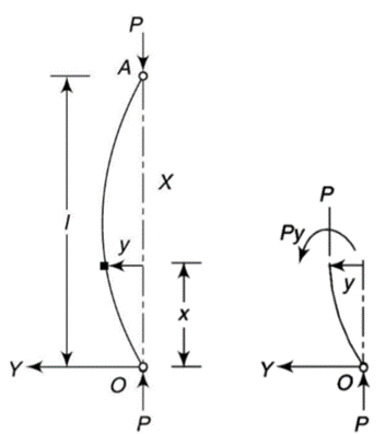
Y-axis is taken in such a way that deflection is positive.
From the equation of bending, viewing from right end,

The equation can be written as

Where, 
The solution of the above equation is

When both ends are hinged.
At  ,
, 

And at  ,
, 

If A = 0, y is zero for all values of load, hence, there is no bending.


Therefore, Euler’s Crippling load,


Comparing above equation with

We get,

2. Both ends fixed
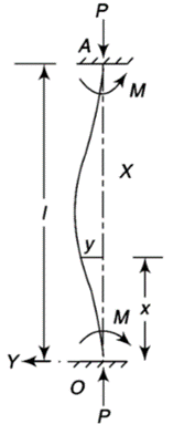
Let M be the end fixing moments, then governing equation becomes,

The equation can be written as

Where, 
The solution of the above equation is


When one end is fixed and other is free.
At  ,
, 

At  ,
, 


At  ,
, 


Therefore, Euler’s Crippling load,


Comparing above equation with

We get,

3. One end fixed and other free
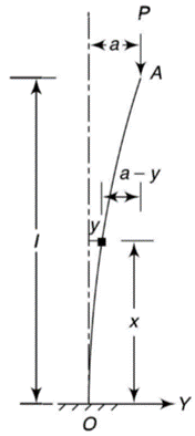
Take Y-axis towards right for positive value of y. Viewing from left we get,

The equation can be written as

Where, 
The solution of the above equation is


When one end is fixed and other is free.
At  ,
, 

At  ,
, 


At  ,
, 


Therefore, Euler’s Crippling load,


Comparing above equation with

We get,

4. One end fixed and other hinged
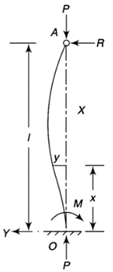
Let M be the fixing moment at end O.
For equilibrium of strut, a horizontal for R acts at free end
Then,

The equation can be written as

Where, 
The solution of the above equation is


When one end is fixed and other is free.
At  ,
, 

At  ,
, 


At  ,
, 


Therefore, Euler’s Crippling load,


Comparing above equation with

We get,

We can summarize the above conditions as given below:
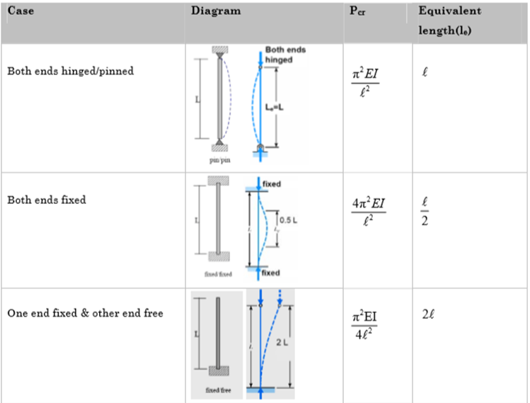

Crippling stress is given by,

The critical stress is directly proportional to modulus of elasticity and inversely proportional to square of slenderness ratio of column.
The graph plotted between critical stress and slenderness ratio is shown in figure below.
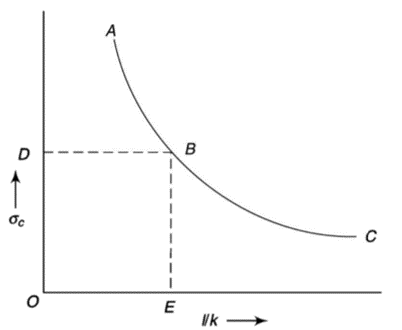
The value of  at point B is called as critical value of slenderness ratio.
For any slenderness ratio above this value, column fails for buckling and for any value of slenderness ratio less than this value, the column fails by crushing and not by buckling.
Hence, for short column, Euler’s Formula is not applicable.
Mathematically, Euler’s Formula is applicable,
If crushing stress  buckling stress


When the slenderness ratio is greater than or equal to  , then the Euler’s formula is applicable. This is the limitation of Euler’s formula.