Unit 6
Application Based Combined loading and stresses
In many structures the members are required to resist more than one kind of loading. For example, a beam can be subjected to the simultaneous moment of bending moments and axial forces (shown in Fig. a), a pressure vessel can be supported in order that it too functions as a beam (shown in Fig. b), or a shaft in torsion can have a bending load (shown in Fig. c). These examples are known as combined loadings.
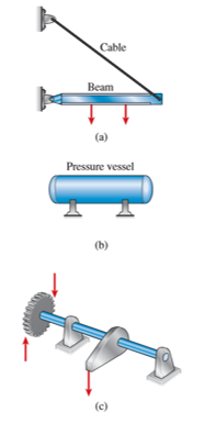
A structural member subjected to combined loadings may usually be analyzed by superimposition of the stresses and strains that are produced by each load acting distinctly. But, superposition of both stresses and strains is permissible only under certain conditions. First requirement is that the stresses and strains must be linear functions of the applied loads, which in turn requires that the material follow Hooke’s law and the displacements remain small. Another requirement is that there must be no interaction between the various loads, that is, the stresses and strains because to one load shouldn’t be affected with the presence of the other loads. Generally, structures satisfy these two conditions, and therefore the use of superposition is very common in engineering work.
The procedure to solve problems of combined stresses includes the following steps:

Consider the bar, subjected to two types of load—a torque T and a vertical load P, both acting at the free end of the bar.
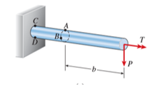
Arbitrarily select two points A and B for investigation. Point A is located at the top of the bar and point B is located on the side. Both points are located at the same cross section.

The stress resultants acting at the cross section are a twisting moment equal to the torque T, a bending moment M equal to the load P times the distance b from the free end of the bar to the cross section, and a shear force V equal to the load P.
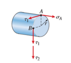
The stresses acting at points A and B are shown in Fig above.
The twisting moment T produces torsional shear stresses.

Where, r is the radius of bar and J is the polar moment of inertia.
 acts horizontally leftward at point A and vertically downward at point B.
The bending moment M produces a tensile stress at point A.

Where, I is the moment of inertia about the neutral axis. Bending moment produces no stress at point B, because B is located on the neutral axis.
The shear force V produces no shear stress at the top of the bar (point A), but at point B the shear stress is as follows:

Where, A is the area of cross-section.
At point A, shear stress  and tensile
  are acting. Hence, at point A we get,


The only stress acting at point B is shear stress  . Hence, at point B


Now that we have determined the stresses acting at points A and B and constructed the corresponding stress elements, we can use the transformation equations of plane stress or Mohr’s circle to determine principal stresses, maximum shear stresses, and stresses acting in inclined directions. We can also use Hooke’s law to determine the strains at points A and B.
The procedure described above for analyzing the stresses at points A and B can be used at other points in the bar.
The design of a structural member generally requires an investigation of the load acting within the member. It is done to make sure that the material can resist the load. When there are internal hinges in any beam or column members, it becomes necessary to determine the internal reaction forces.
As well as calculating the forces and moments transmitted through joints between members, we can also calculate the internal forces which one part of a member exerts on another. Internal loadings can be found by the method of sections.
The procedure to calculate internal forces is as follows:
To find the reactions at external supports, condition of equilibrium is used. These conditions of equilibrium are:

b. Algebric sum of the forces in Y direction is equal to zero

c. Algebric sum of the moments at a particular point due to all forces is equal to zero.

iii. Find reactions at connections.
iv. Keep all loads in their exact locations.
v. Pass a section cut through the member perpendicular to its axis at the point where the internal loads are to be determined,
vi. Draw FBD of cut member.
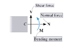
vii. For 2D problem find N, V, M (normal force, shear force and moment respectively) from equilibrium.
Consider the following member.
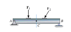
In the above example, first step is to draw FBD of the entire body and finding the support reaction of forces by using equilibrium equation.
At point A, there will be one horizontal reaction force  and one vertical reaction force
At point B, as there is the roller support, there will be only one reaction force, in vertical direction, 
To find the internal reaction forces and moments at point C pass an imaginary section cut through C, cutting the beam into two segments.
Draw the FBD for each section shown below:

FBD for each section
The forces and moment applied by the left-hand side onto the right-hand side are equal in magnitude but opposite in direction to the forces applied by the right-hand side on the left-hand side. Internal loadings on entire beam appear as external loads. Each segment must be in equilibrium.
We apply equilibrium equations to a segment and solve for internal force components.
There are two types of couples viz, bending couple and twisting couple. When these two couples acts in same or two different planes, then the system is said to be 2D system with couples.
In such cases, stresses are set up due to bending moment, torque and shear force. However, shear stress due to shear force is usually unimportant as its maximum value occurs at the neutral axis where the bending stress is zero.
Let,
 be the bending stress and
 be the maximum shear stress due to twisting
The for solid shaft under combined couples,

Where,
M is the bending couple or bending moment
T is the twisting couple or torque
D is the diameter of shaft
For vertical loading on shaft, the maximum values of bending stress occurs at the ends of vertical diameter whereas maximum value of shear stress at outer surface. As there is no normal stress on the longitudinal planes of the shaft,
Maximum principal stress is,


 is referred to the equivalent bending moment that would give same maximum bending stress.
Maximum shear stress is,


 is referred to the equivalent torque that would produce the same shear stress.
Let a column be acted upon by a thrust F, the line of action of which cuts the cross-section at a point on the x-axis at a distance h from the centroid O. If two equal and opposite forces are introduced along the axis of the column, then the system becomes equivalent to the load at O that produces a uniform direct stress along with a bending moment  about y-axis, producing a varying bending stress.
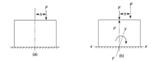
Then the combined compressive stresses at any point at a distance  from YY,

Where, A is the cross-sectional area
If  taken positive on the same side of the y-axis as the load, then bending stress will be of same type of direct stress and taken and positive. On left side,
  is negative and thus the sign taken is negative. And thus at the left edge o the section, stress will depend upon the value of the right term of the above equation i.e. it is more or less.
Stress distribution is given below:

The above condition is when the load is eccentric to one axis.
In case, when load is eccentric to both axes as shown below.
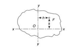
It will be equivalent to central load and bending moment about the two axes.
In the above equation, x and y are taken positive when on the same side of the axes as of the load.
In masonry column, it is desirable that tensile stresses are not set up. It is achieved if the line of action of load lies within the central area of the section. This central area is called as kernel or core of the section.
Shape of the kernel depends on the profile of the section.
Rectangular section
Consider the rectangular section with width b and depth d.
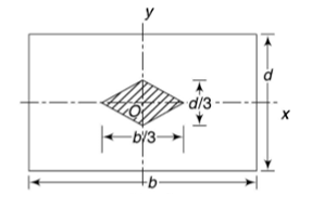


The tensile stresses may be developed if, x and y are negative.

In limiting cases if  and
and  ; and
; and


This equation gives the limiting values of h and k. In each quadrant the load must lie in the line produced by this equation.
When  and when
It shows that when the load lies on the either axis, it should lie on the middle third in the cross-section to avoid the tensile stress. Hence, the load must lie in the diamond area.
For the rectangular section, maximum eccentricity is  in x-direction and
  in y-direction.
Circular section
Consider the circular section with diameter d as shown below
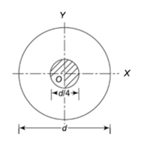
The maximum stress along any axis of diameter is


In limiting cases,  and
and


The equation gives the limiting value of eccentricity for all possible positions of the load. The kernel is the circle of diameter  with center O. To avoid tensile stress, load must lie within this section.
There come many times when there are radial and tangential forces are applied on the shaft.
The radial force subjects to direct shear stress. This radial force is called as shear force. Direct Shear stress is given by,

Where,
S is shear force
A is the area above the neutral axis
 is the distance of NA to the point where shear stress is found
I is the moment of Inertia
b is the width of the shaft
Direct shear stress is maximum at neutral axis
At neutral axis for a solid shaft,


Maximum direct shear stress is


The tangential force subjects torque on the shaft resulting into torsional shear stress.
Torsional shear stress is given by,

Where, T is the torque and  is the polar Sectional Modulus
For the solid shaft,

Hence, torsional shear stress is given by,


Total shear stress is given by,

Maximum shear stress at any point subjected to combined direct and torsional shear stress is given by

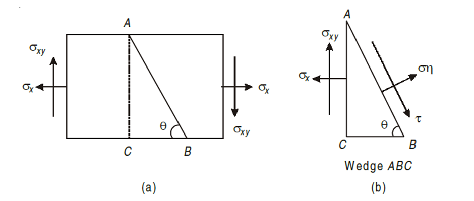
Consider a rectangular body of a uniform cross-sectional area and unit thickness subjected to a direct tensile stress along x – x axis accompanied by a positive (i.e., clockwise) shear stress along X-X axis
Let,
σx = Tensile stress in x – x direction.
τxy = Positive (i.e. clockwise) shear stress along x – x axis
θ = Angle which oblique section AB makes with x – x axis in clockwise direction.
Normal stress is given by,
 +
+
Tangential stress is given by,  -
- 
Resultant stress is given by,
 t
t
Major principal stress is given by,

Minor principal stress is given by,

Location of principal plane

Maximum shear stress,

= ±
Major principal strain 
Minor principal strain 
