Unit 1
Fundamentals of 3D modeling
Modeling is basically the process of taking a shape and molding it into a completed 3D mesh. The most typical means of creating a 3D model is to take a simple object, known as primitive, and extend or "grow" it into a shape that can be refined and detailed. Primitives can be a single point (called a vertex), a two-dimensional line (an edge), a curve (a spline), to three dimensional objects (faces or polygons).
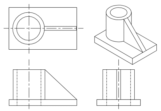
3D modeling is that the process of developing graphics and pictures that appear to possess three dimensions. But generally, it involves connecting a set of points with various geometric data such as lines and curved surfaces with the goal of creating a wireframe model that represents a three-dimensional object. Computer aided design and drafting (CADD) is a powerful technique to create the drawings. Traditionally, the components and assemblies are represented in drawings with the assistance of elevation, plan, and end views and cross-sectional views. In the early stages of development of CADD, several software packages were developed to form such drawings using computers. Figure below shows four views (plan, elevation, end view and isometric view) of a part. Since any entity during this kind of representation requires only two co-ordinates (X and Y) such software packages were called two-dimensional (2-D) drafting packages. With the evolution of CAD, most of those packages are upgraded to enable 3-D representation.
Designers typically use one of four main modeling methods, namely-
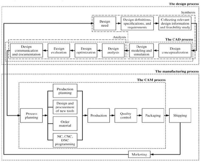
Fig. Typical Product Life Cycle
Design process: The product goes through two main processes from inception to a finished product which are the design process and the manufacturing process. Synthesis and analysis are the 2 main subprocesses of the planning process.
Synthesis: The philosophy, functionality, and uniqueness of the product arc all determined during synthesis process. During synthesis, a design takes sketches and layout drawings that show the relationship among the various product parts. These sketches and drawings are usually created using a CAD/CAM system or just hand-drawn on paper. They are used during brainstorming discussions among various design teams and for presentation purposes.
Analysis: The analysis subprocess begins with an effort to place the conceptual design into the context of engineering sciences to measure the performance of the expected product. This requires design modeling and simulation. An important aspect of analysis is that the "what if' questions that help us to eliminate multiple design choices and find the most effective solution to every design problem. The outcome of analysis is that the design documentation within the form of engineering drawings (also referred to as blueprints).
Manufacturing Process: The manufacturing process begins with the process planning and ends with the actual product. Process planning is taken into account the backbone or the manufacturing process since it attempts to determine the most efficient sequence during which to produce the product. A process planner must be aware of the varied aspects of manufacturing to plan properly. The planner typically works with the blueprints and should communicate with the design team to clarify or request changes within the design to suit manufacturing requirements. The outcome of the process planning may be a production plan, tools procurement, material order, and machine programming. Other special manufacturing needs like design or jigs and fixtures or inspection gages are planned.
Product Life Cycle Management
Product life cycle Management (PLM) is a system of managing the entire life cycle of the product.
PLM is that the Business Strategy of managing the whole lifecycle of a product from its conception, through design and manufacture, to service and disposal.
It Supports the Extended enterprise (Customers, Design and supply partners). PLM Spans from the Concept to the last stage – the life of a product or plant.
Need of PLM
“The use of computer systems to assist in the creation, modification, synthesis, analysis and optimization of a design of any product, machine or component of machine is defined as Computer Aided Design.”
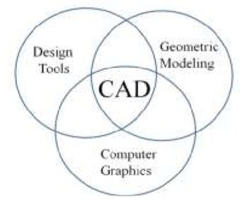
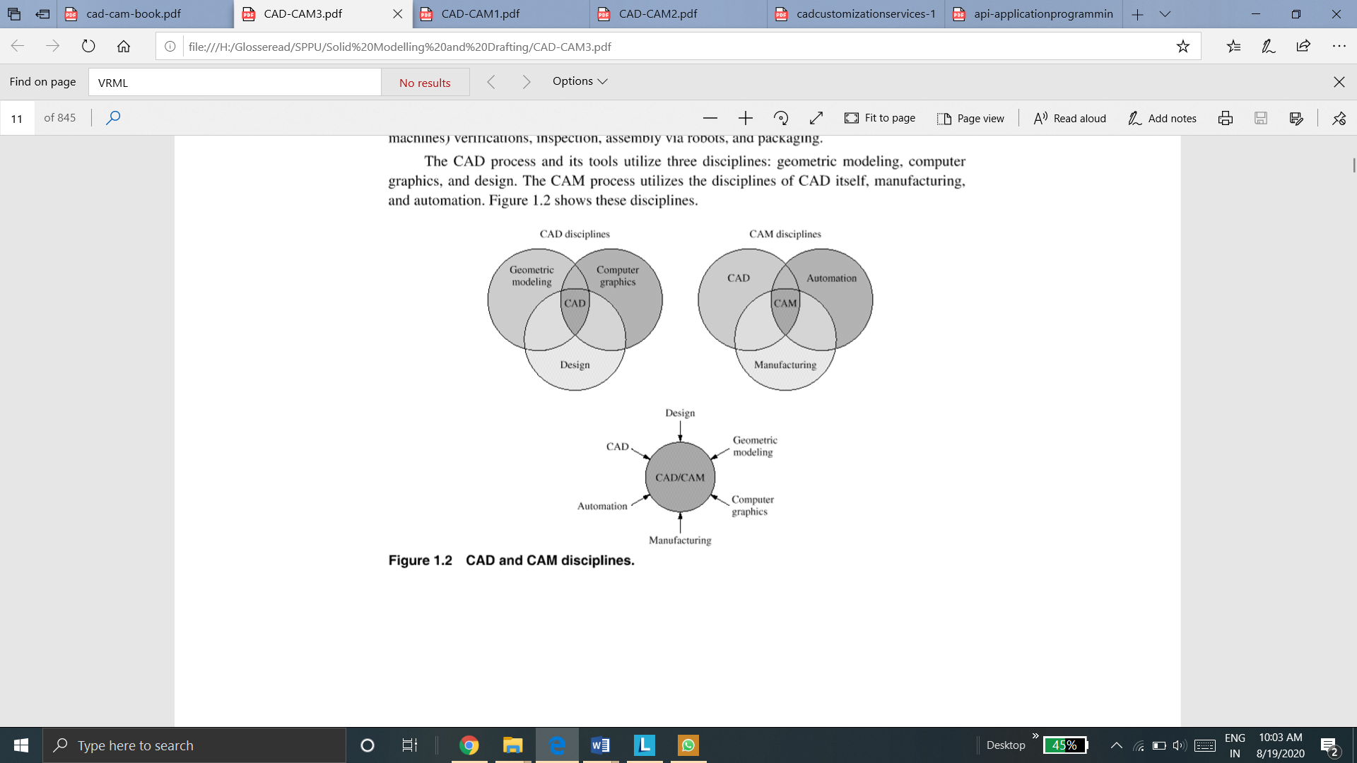
CAD is the combination of Computer Graphics, Geometric modeling and Design tools (Fig). The concepts of computer graphics and geometric modeling must be used innovatively to serve the design process. CAD is that the function of computer systems to support within the creation, modification, analysis, or optimization of a design.
Requirements of CAD
Essential requirements of CAD is shown below
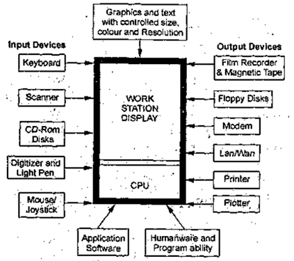
2. Software requirements
Application of CAD
Main Applications of Computer Aided Design (CAD)
Solid Modeling
This process is used to form solid components of desired shape by joining and cutting different solid volumes. The final solid model may be a virtual replica of an actual product but it are often seen and rotated sort of a real product.
Surface Modeling
This process is used to form surfaces of desired shape by trimming, stitching and joining different surfaces to create a final shape model.
Assembly
This process is used to assemble the models created in solid or surface modeling to create a final assembly. This is used to see the particular fitment of all models and see the actual working of assembly.
Drafting Detailing
This process is used to form the 2D drawings of components or assemblies; usually directly from a 3D model, although 2D CAD can create 2D drawings directly.
Reverse Engineering
This process is employed to convert the real component into 3D CAD Model. Different types of instruments like laser scanner, white light scanner, CMM (coordinate measuring machine) etc. are used to measure or decode the shape of real model. The virtual model obtained can then be modified during a CAD program
The CAD process and its tools uses three disciplines: geometric modeling, computer graphics, and design. The CAM process utilizes the disciplines of CAD itself, manufacturing, and automation. Figure below shows these disciplines.
Design process of product cycle
The design process contains series of steps that engineers apply in making functional products and processes. The parts of the process often got to be repeated repeatedly before production of a product can start. The parts that get iterated and therefore the number of such design cycles in any given project are often highly changeable.
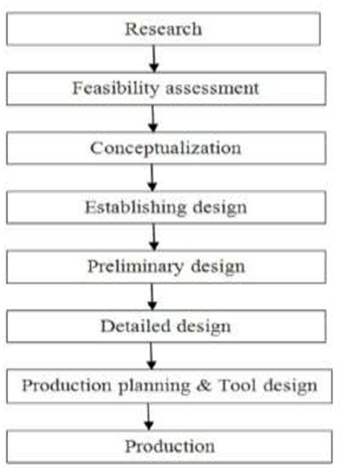
Design Process
CAD Tools
The different CAD tools that are used to perform various steps in design process is given below:
CAD system provides many sketching commands/tools, which allow us to create various 2D shapes using geometrical entities such as lines, circles, arcs, fillets, rectangles and chamfers. All CAD systems provides these sketching tools.
2. Modelling tools (3D operations)
We take the sketches that we create and apply various 3D operations to them to obtain different features and surfaces which we call CAD models. CAD system offer many 3D operation for solid and surfaces such as extrusion, revolve, cut, holes, ribs, chamfers, fillets, sweeps and lofts. These commands can be selected using the menu-bar or toolbar approach. 3D operations may require more than one sketch I order to completely define the feature or surface.
3. Viewing command
Once the object is created using 3D operations, or while in the process of creating models and sketches, CAD system enables us to view those models in many different ways. Most of the viewing operations on CAD system can be divided into three groups: view orientation, view modes, and view manipulations.
View orientation contains standard views such as front, top, right, and isometric. They basically align the object on screen such that it displays selected views.
View modes enables us to change the display of the model to different types such as wireframe, hidden, or shaded.
View manipulation enables us to dynamically rotate, pan, and zoom the model to gain better control over its viewing.
4. Productivity tools
All CAD system offer certain productivity tools/features that reduce the time required to create a model and also increase the accuracy of the model. Examples of productivity tools are geometric modifiers, geometric arrays and grids.
5. Management tools
CAD system offer management tools so that a user can group together the entities of similar nature, which in turn assists in editing, visualization, and efficient access to CAD models. Some of the management tools that CAD system offer are layers and colors.
6. Editing tools
These are used when one needs to retrieve the model later by opening its file to resume its modelling by performing new CAD/CAM operations. These operations contains either editing the existing model definition or adding new entities to it.
7. Coordinate system and sketch plane tools
Coordinate system and sketch plane are most important concepts in a CAD system. They are generally used to input, store and display model geometry and graphics. The three coordinate systems that achieve these tasks are Model coordinate system, working coordinate system, and screen coordinate system.
The major available modules are given below:
The operating system (OS) module offers functions for interacting with the operating system. This module offers a portable way of using operating system dependent functionality. This model assists the CAD/CAM system or software to interact with the operating system of the computer.
The geometric module is the heart of a CAD/CAM system. It offers users with functions to perform geometric modeling and construction. Editing and manipulation of existing geometry, drafting and documentation is enabled. This is the typical modeling operations that users can engage in arc model creation, cleanup, documentation, and printing/plotting. Shaded images can be produced as part of model documentation.
The applications module varies from one software system to another. However, there are common applications of most CAD/CAM systems. Mechanical applications contain mass property calculations, assembly analysis, tolerance analysis and synthesis, sheet metal design, finite element modeling and analysis, mechanisms analysis, animation techniques, and simulation and analysis of plastic injection molding. Manufacturing applications contain CAPP, NC, CIM, robot simulation, and group technology.
The programming module enables users to customize systems by programming them to fit certain design and manufacturing tasks. A CAD/CAM system needs advanced knowledge of the system architecture, its database format, and a high-level programming language such as C, C++, Java, Scheme, or others.
The communications module is important if integration is to be achieved between the CAD/CAM system, other computer systems, and manufacturing facilities. It is general to network the system to transfer the CAD database of a model for analysis purposes or to transfer its CAM database to the shop floor for production. This module also provides the purpose of translating databases between CAD/CAM systems using graphics standards such as IGES and STEP.
The collaborative module is emerging as an output of the widespread of the World Wide Web and the Internet. This module helps collaborative design. Various design teams in different geographical locations can work simultaneously on the same part, assembly, or drawing file in real time over the Web. One team can make changes and other teams can view and accept or reject.
There are various modeling approaches to make a 3D model. Some of them are:
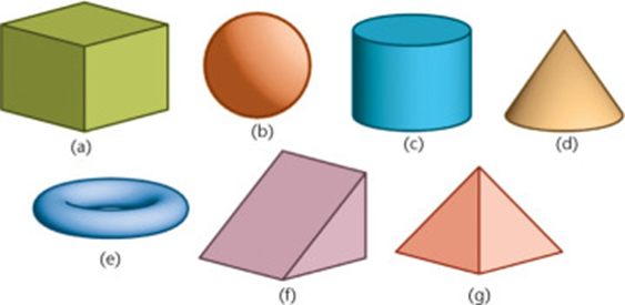
Many 3D objects can be visualized, sketched, and modeled in a CAD system by combining different and simple 3D shapes called primitives.
A 3D model of an object is generated by using a 3D geometric-entities known as primitives. They are the building blocks for many solid objects.
A common set of primitive solids that are used to build more complex objects are shown in figure.
A desired solid can be obtained by combining two or more solids.
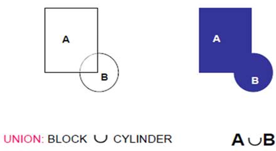
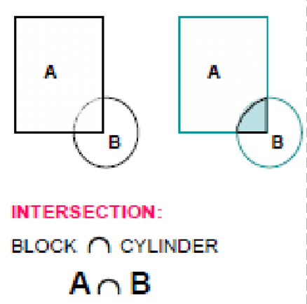
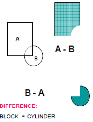
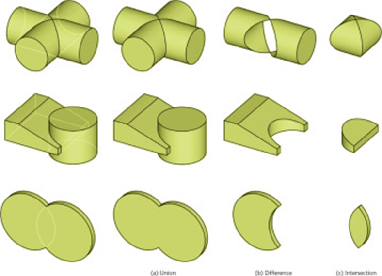
When we use Boolean set of operations on two or more primitives, it gives a desired solid geometry.
Normal Boolean operations are union, intersection and subtraction which are given below
1) Union
2) Intersection
3) Difference
2. Feature and sketch based modeling
Now-a-days, feature based modeling is most widely used approach of creating a 3D model.
Feature is defined as the combination of shape and operation to build the parts.
Shape is a 2D sketch.
Operation is an activity that converts the sketch into a 3D shape.
Steps in Feature and sketch based modeling are
First step is to create the shapes or sketches. A shape is a 2D profile or a cross-section.
ii. Create features
Apply feature operations to the sketches created in previous step. Different feature operations are extrude, revolve, sweep, loft, etc.
iii. Combine features
Different features are combined to form a 3D model.
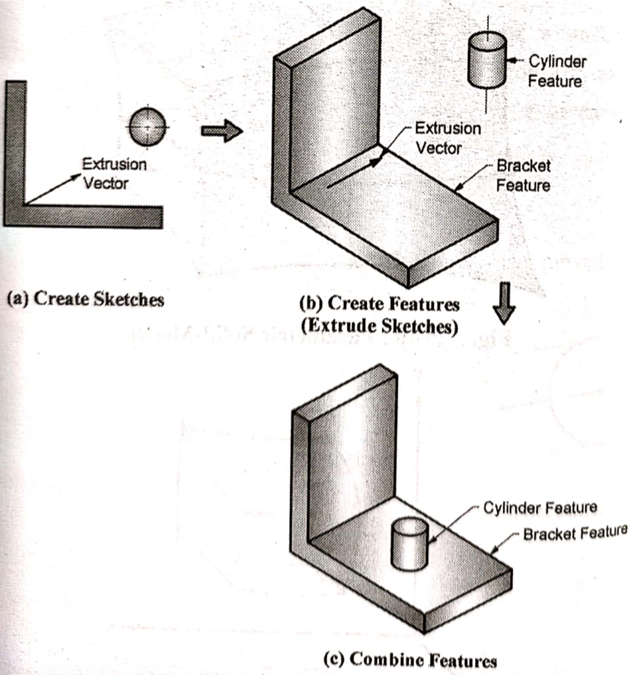
Most of the CAD softwares like Solidworks, CATIA, etc. uses this approach to create a 3D model.
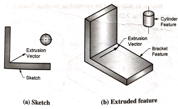
Extrude command is used to create 2 ½ extrusion models with a uniform thickness.
To create this type of models, a 2D sketch is required. This 2D sketch is the cross section of the desired model. Another input required to create this kind of model is a extrusion vector. The extrusion vector is always perpendicular to the plane of sketch. 2D sketch is extruded in a direction of extrusion vector, hence called as 2 ½ extrusions.
First step, we create the cross section in a sketch plane. Second, we extrude the cross section if the model has uniform thickness.
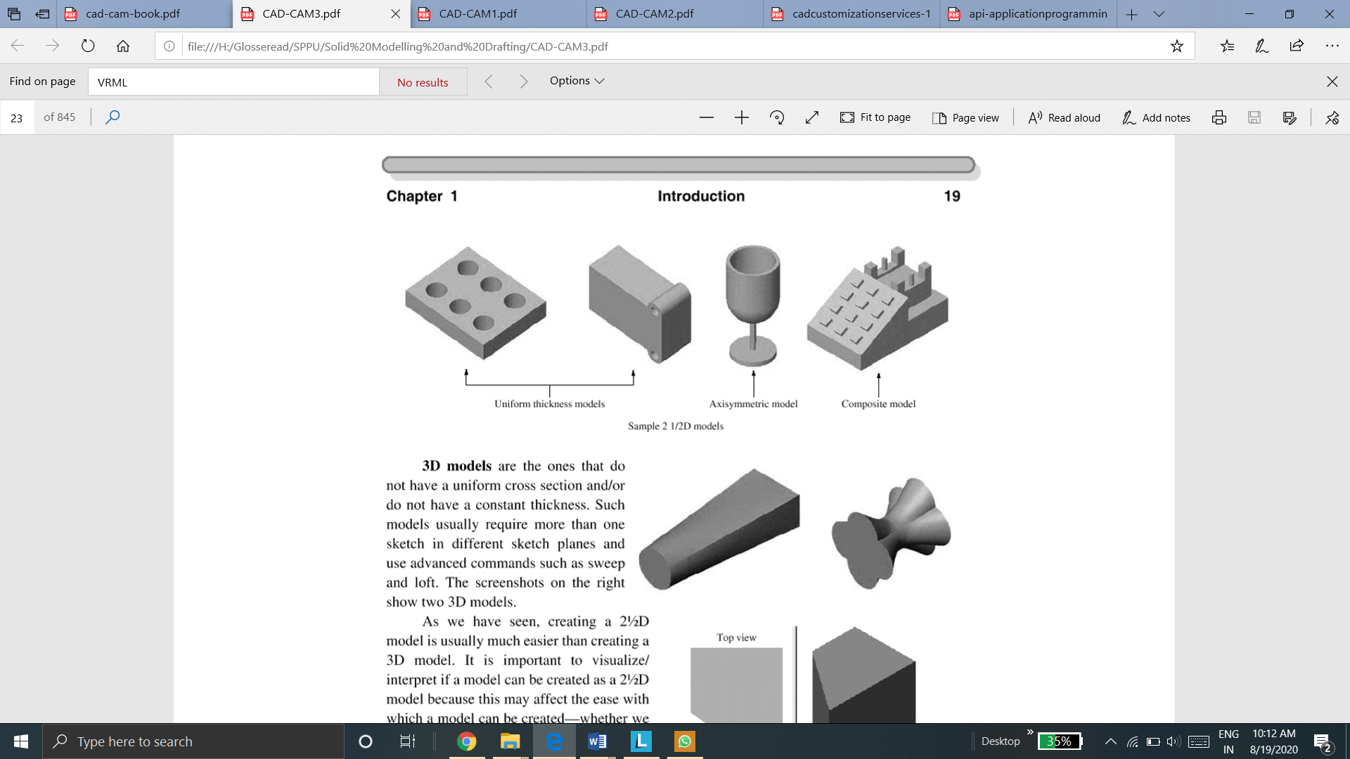
2 ½ D extrusion models
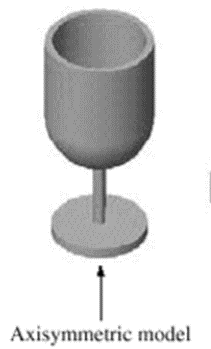
2. Axisymmetric models
Axisymmetric models are the models which are symmetric about its axis.
These are also the type of 2 ½ D models.
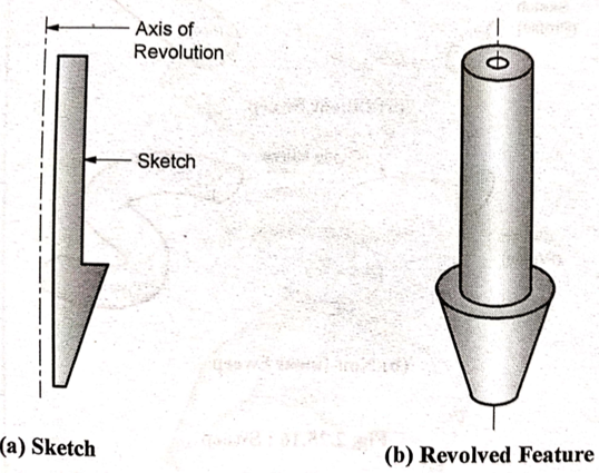
Revolve feature is used to create such kind of models. The input to create these models are a 2D sketch and axis of symmetry (revolution vector). Sketch and axis are in same plane. Sketch can be revolved for different angles to revolve. 360o revolve gives a full revolved sketch as shown below.
First, we create a sketch in the sketch plane with axis to revolve.
Second, we use revolve command and revolve the sketch about the axis for the required angle of revolution to create 2 ½ D axisymmetric model.
3. Composite models
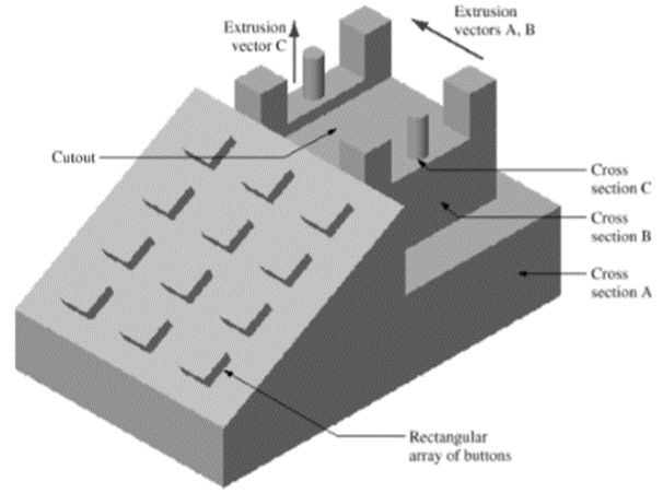
A composite geometric model is combination of 2 ½ extrusion or axisymmetric models with addition to some other features like boss, cut, fillet, chamfer, etc.
The composite object is the combination of multiple 2 ½ extrusion or revolve objects. These objects may have multiple extrude, revolve, cut, boss, hole, chamfer, fillet, etc. operations on the base 2 ½ model.
The model shown in a figure is a composite model. We extrude the three cross-section in the direction shown, cut out the excess material between the handset support pins, and use a rectangle array to create the buttons.
4. 3D object
3D objects are those who don’t have uniform cross-section and/or do not have uniform thickness. Such models usually requires more than one sketch planes and use advance commands such as sweep and loft.
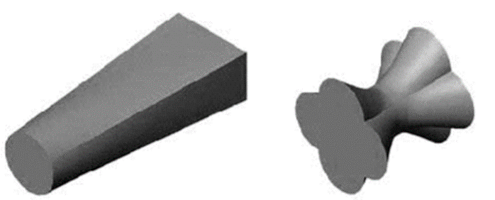
3D modeling is the process of developing graphics and images that have three dimensions. The process is complicated, but generally includes connecting a set of points with various geometric data such as lines and curved surfaces with the goal of creating a wireframe model that represents a three-dimensional object.
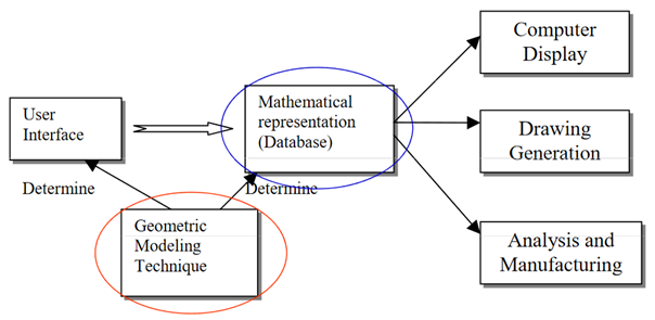
Role of geometric model in CAD system
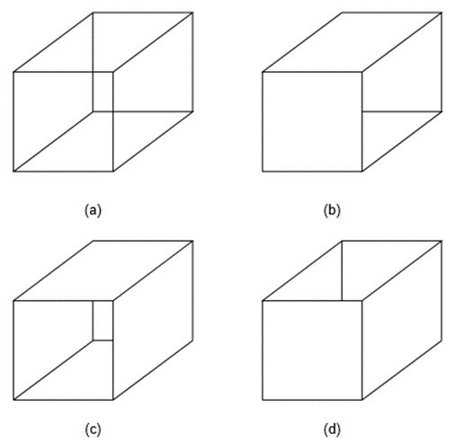
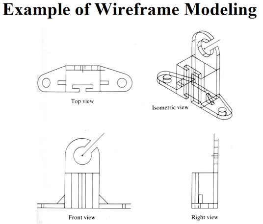
In wire frame modeling the object is represented by its edges. In the initial stages, wire frame models is in 2-D. Subsequently, 3-D wire frame modeling software was introduced. The wire frame model of a box is shown in Fig. (a) below. The object appears as if it is made out of thin wires. Fig.(b), (c) and (d) show three objects which could have the same wire frame model of the box. Thus, in the case of complex parts wire frame models can be very confusing. Some clarity can be achieved through hidden line elimination. Though this type of modeling may not offer unambiguous understanding of the object, this has been the method traditionally used in the 2-D representation of the object, where orthographic views like plan, elevation, end view etc. are used to describe the object graphically.
2. Surface Modeling
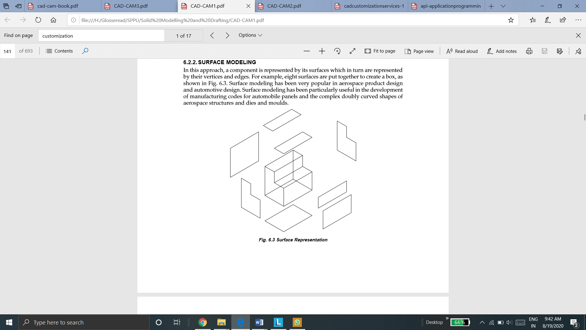
In this approach, a component is represented by its surfaces which then are represented by their vertices and edges. For example, eight surfaces are put together to create a box, as shown in Fig below. Surface modeling has been very famous in aerospace product design and automotive design. Surface modeling is very useful in the development of manufacturing codes for automobile panels and the complex doubly curved shapes of aerospace structures and dies and molds.
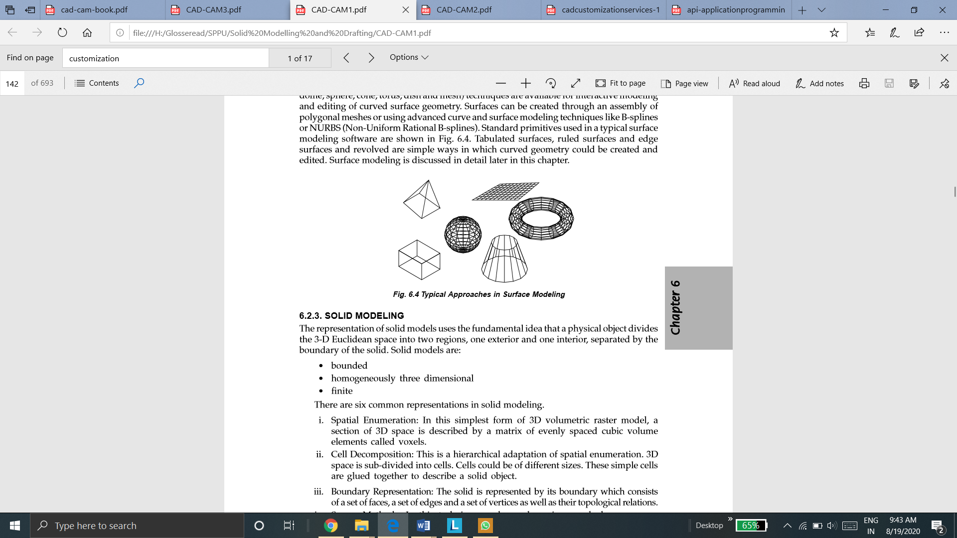
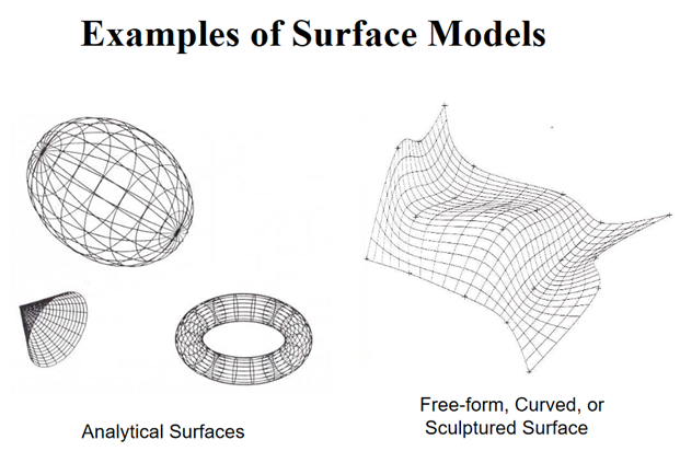
Apart from standard surface types available for surface modeling (box, pyramid, wedge, dome, sphere, cone, torus, dish and mesh) these techniques are available for interactive modeling and editing of curved surface geometry. Surfaces can be generated through an assembly of polygonal meshes or using advanced curve and surface modeling techniques like B-splines or NURBS (Non-Uniform Rational B-splines). Standard primitives used in a basic surface modeling software are shown in Fig. Tabulated surfaces, ruled surfaces and edge surfaces and revolved surfaces are simple ways in which curved geometry could be created and edited
3. Solid Modeling
The representation of solid models uses the bsic idea that a physical object divides the 3-D Euclidean space into two regions, one exterior and one interior, separated by the boundary of the solid.
Solid models are:
• bounded • homogeneously three dimensional • finite
There are six common representations in solid modeling.
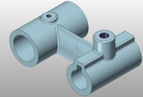
There are three basic 3D modeling strategies that can be employed to create standard 3D models
Spline or Patch Modeling In 3D space, a spline simply refers to a curve with two control points. NURBS and Bezier curves are the most popular splines used in a 3D art. If you are looking to create a 3D object, you can use a cage of splines to form the “skeleton.” while generting a 3D skin around the shape, a path of polygons can be formed to extend between two splines. The use of splines to build models can be the oldest form of 3D modeling. Spline modeling must be your first choice when forming a 3D scene that involves curve shapes. However, it is important to note that due to the long period of time associated with using this strategy, many 3D artists don’t see the need to apply it for their 3D modeling projects these days.
Box Modeling To start with, a primitive (such as a cube) is formed. Then after slicing the cube, details are added until the desired form is obtained. While bearing a lot of resemblance to traditional sculpting, box modeling is probably the most popular technique used for 3D modeling. This strategy presents a very quick and easy means to get acceptable results. Most 3D artists use this to create the basic shape of the model they want to form.
Poly Modeling / Edge Extrusion Although poly modeling may seem to be the most précised and effective strategy for handling 3D modeling projects, it is certainly not the easiest to get started with. This technique includes the creation of 3D mesh face-by-face, point-by-point. To get it “just right” this technique requires less tweaking of the mesh even though it is not as fast as box modeling.
Usually, it requires the use of a single 3D object consisting of 4 points (i.e. quad) to start out. This way, the 3D model is gradually created as a second quad attached to the first which is formed by extruding an edge of the quad.
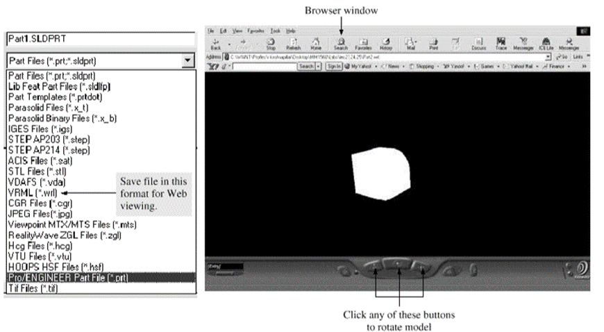
VRML (Virtual Reality Modeling Language) enables us to display CAD models in a Web browser. Moreover, we can manipulate these models. For example, we can rotate a 3D view in the browser window to look at other invisible sides of it.
We need to use CAD system to generate a VRML file before we can use the VRML plug-in. While the CAD system is running, save the CAD file in VRML format to generate a VRML file. Simply click this sequence:
File – Save As—select the VRML filename. The VRML file extension is .wrl.
We need a browser window to open the .wrl file to view it. While the VRML file is open in the browser window, we manipulate it using the buttons offered by the plug-in as shown below.
VRML is a standard file format for three-dimensional graphics data, whereas CGM and DWF are two-dimensional formats. Although VRML has limitations, such as loss of accuracy and large file sizes, most geometric modeling system vendors have opted to go with the VRML output capability because of VRML's support for three-dimensional work. Some even go a step further, providing the ability to put the VRML model into a Web page and add information such as text and hyperlinks to the page. Just as in Hypertext Markup Language (HTML) hypertext links-now used to link to other World Wide Web (WWW or the Web) data VRML files contain URLs that can point to any other type of file on the Web, including other VRML files. When VRML files are read by a viewer, a navigable three-dimensional model appears. Hot spots (links to other URLs) are identified by a graphical change in the cursor, much like the user encounters on HTML pages [Beazley 1996]. Clicking the mouse on a hot spot loads the file associated with the hot spot. By clicking on the different parts of a model, for instance, a user can open a window that displays information written by another member of the design team. When clicking on a different corner of the image, the user can read technical characteristics about the model and can see concerns posted by someone else on the team.