Unit 3
Solid Modeling
A set of principles that apply in a computer-aided design (CAD) context is referred to a Solid modeling. It is particularly when it is to simulate 3D objects.
How the eventual object would look like is forecasted by a solid modeling system and this system ensures that the design of the object is geometrically correct or not. It has enabled difficult engineering processes to be automated. Solid modeling also supports key processes in manufacturing like machining and assembly.
The solid modeling uses topological information as well as the geometrical information in order to represent the unambiguous and complete object. The solid definitions contains vertices (nodes), edges, surfaces, weight, and volume. Complete, valid and unambiguous geometric representation of physical object is the base of Solid modeling.
Solid modeling is the easiest and the most advanced way of geometric modeling. The wireframe model and surface model contains only the geometric data, while solid modeling contains topological information in addition to geometric data. Solid modeling is considered as the technological answer to integrate the design and manufacturing.
Solid model may be converted into wireframe model in the CAD software. This type of conversion is used to automatically generate orthographic views of the model. However, it is not possible to convert wireframe model into solid model due to its incomplete and ambiguous nature.
Solid modeling software helps to create precise models of parts and assemblies.
Analysis automation and integration is allowed only using solid models. Solid models has properties like weight, mass, moment of inertia, etc.
Solid model is created with the help of CAD softwares like AutoCAD, Solidworks, CATIA, CREO, etc.
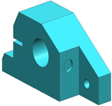
Geometry
Geometry is referred to the actual dimension that are used to define the entities of the object.
The graphical information like dimension, length, angle, area and transformations is the geometry of the model. Geometry gives the dimensions and locations of the solid object in a chosen coordinate system.
Topology
Topology is the connectivity and associativity of the different entities of the object. It describes the way in which the different entities of the object are connected together.
Topology gives the invisible information about the connectivity, neighborhood, associatively, etc.
Following figure shows shame geometry but different topology
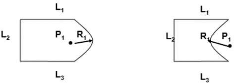
In the above figure, all geometric properties like lengths of line L1, L2 and L3, angle between these lines, radius of arc R1 and position of center of arc P1 are same in both figure. But due to different topology, both objects seem different.
Similarly, there exists two models with same topology but different geometry.
It is important to note that, neither topology nor geometry alone can completely define a solid model. A model to fully define needs both geometrical and topological data.

The above figure shows the different geometry with same topology.
The entities which are used to create solid models generally depends on the approach used. The primitive technique makes use of primitives and the features technique makes use of sketches. Various CAD systems provide both approaches in order to increase their modeling domain.
Primitives are referred as the building blocks of a solid model.
Solid entities are the basic building blocks of solid modeling.
Following are the most commonly used solid entities.
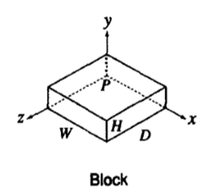
It is defined by height H, width W, and depth D. Its local coordinate system is (x, y, z) and origin O.
2. Cylinder
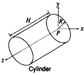
Cylinder is defined by radius R and height H.
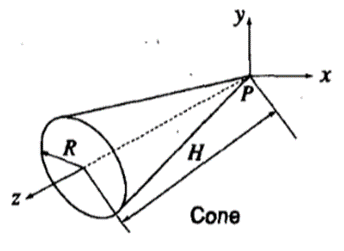
3. Cone
It is defined by its bas radius R and height H.
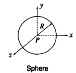
4. Sphere
Sphere is defined by radius R.
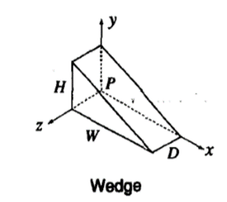
5. Wedge
Right angled wedge is defined by its height H, width W and depth D.
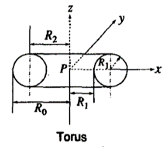
6. Torus
The torus is generated by revolution of circle about an axis laying in its plane. It is defined by inner radius Ri and outer radius Ro. It can also be defined by the radius of center line R2 of the torus body and radius of the body R1.
All these solid entities can be created using feature approach. They are all 2 ½ D objects. The block, cylinder and wedge are of uniform thickness. The cone, sphere and torus are axisymmetric.
Solid model gives complete, valid and unambiguous representation of physical object.
Basic Fundamentals of solid modeling are:
Geometry relates to the data which contains contains shape-defining parameters, like the coordinates of the vertices in a polyhedral object. Topology is the connectivity and associativity of the different entities of the object, i.e. the relational information between the different parts of an object.
2. Geometric closure
The solid models are finite in nature. These models are bounded in geometry. These models are non-dangling, all bodies are fixed or fully defined.
3. Set Theory
A set is defined as any collection of objects which are called as “elements” or “members.”
Universal set W, contains all points in E3 space, and the null set, Ø, is empty or has no elements.
Various set operations are: union (∪), intersection (∩), difference (–).
4. Regularized set operations
Boolean operations validates the validity of geometric models by avoiding the generation of wrong objects.
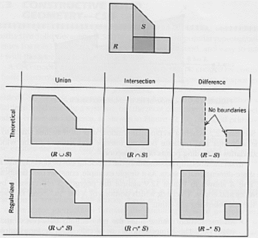
Conventional (regularized) and theoretical set operations.
5. Set membership classification
Set membership are classified into two sets X and S. It validates how various parts of X can be assigned to S by checking whether points are on its interior, exterior, or on its boundaries. X is divided into 3 subsets XinS, XonS, XoutS.
XinS means the part of X which is in S.
XonS means the part of X at the boundary of S
XoutS means the part of X which is out of S
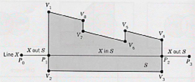
The solid representation of an object is based on the idea that a physical object classifies an n-dimensional space En into 2 regions: viz, interior and exterior which are separated by the object boundaries.
Mathematically, a point set S in the three-dimensional Euclidean space E3 is referred to any solid model.

Where, iS is the interior point set while bS is the boundary set.
iS represents the set of points which are in the interior of the solid mode.
And bS represents the set of points which are on the boundary or surface of the solid object.
The universal set can be defined as

Where cS refers to complementary set of iS U bS
The complementary set cS shows the points which are neither in the interior of the solid object nor on the boundary of solid model.
These are the points which are exterior of the solid model.
Consider the following example. It will elaborate the concepts of interior, boundary closure and exterior
Consider a unit sphere shown in figure
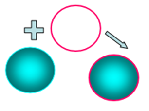
The sphere and its boundary together represent a closure.
And whatever is outside of this closure is exterior.
Mathematically,
Interior of sphere is represented as,

Boundary of sphere is represented as,

Hence the total closure is represented as,

Its boundaries geometrically closed the interior of the solid

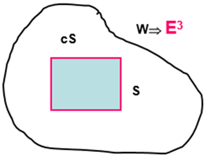
Properties of solid entities:
Part of a n-dimensional space produced by removing that part lying on one side of a n-dimensional hyperplane is called as half space.
In geometry, a half-space can be one of the 2 parts in which a plane divides the 3D Euclidean Space. More specifically, a half-space is one of the two parts in which a hyperplane parts an affine space. Means, the points which are not incident to the hyperplane are divided into two convex sets (i.e., half-spaces), such that any subspace connecting a point in one set to a point in the other should intersect the hyperplane.
A half-space is open or it is closed. An open half-space is one of the two open sets produced by the subtraction of a hyperplane from the affine space. A closed half-space is the union of an open half-space and the hyperplane which defines it.
If the space is two-dimensional, then a half-space is called a half-plane (open or closed).
A half-space is that portion of an  -dimensional space obtained by removing that part lying on one side of an
  -dimensional hyperplane. For example, half a Euclidean space is given by the 3-dimensional region which satisfy
  ,
,  ,
,  , while a half-plane, is referred by the 2D region satisfying
  ,
,  .
.
A half space is a regular point set in E3 and is given by:

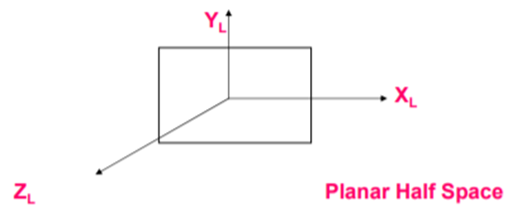
There are various types of half spaces:
A planar half space is represented as:

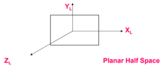
Planar half spaces are classified as Unevaluated boundary based, spatial based.
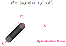
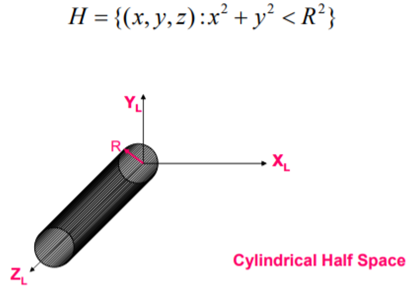
2. Cylindrical half space
A cylindrical Half Space is a given by:
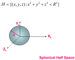
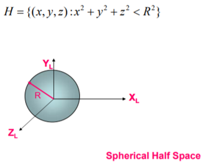
3. Spherical half Space
A spherical Half Space is a given by:
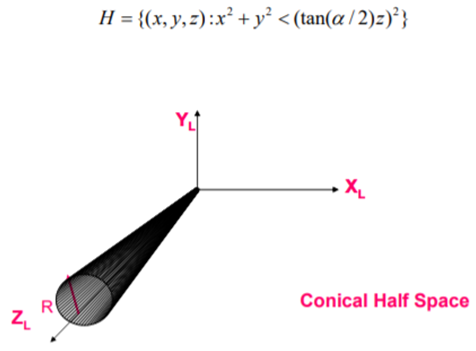
4. Conical Half Space
A conical Half Space is a given by:
5. Toroidal half space
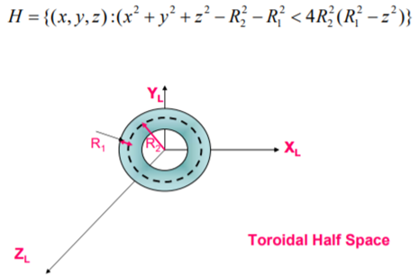
A toroidal Half Space is a given by:

Construction of solid model from half spaces
A solid model can be created by combining different half spaces. Complex objects can be constructed by combining Half Space with the help of set operations.
Set operations are used to create a solid model from half spaces.
Advantages:
Disadvantages:
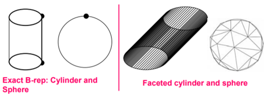
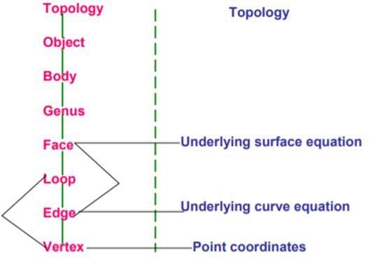
Solid model is defined by their enclosing surfaces or boundaries. This method contains the geometric data of the faces, edges and vertices of an object as well as the topological data on how these are connected to each other.
A closed space in 3D space (surface connect without gaps) represents a solid. Points inside and points outside solid are separated by the boundary.
The B-rep is constructed on the concept that a physical object is packed by a set of faces, which belongs to a closed surface.
A B-rep object is pictured in figure below:
A boundary representation of a solid model consists of:
B-Rep can be represented by two schemes:
A data structure of a B-Rep model is given below:
Data structure of B-Rep
Each feature in B-Rep model is varied independently. Geometry is kept in parallel with object topology.
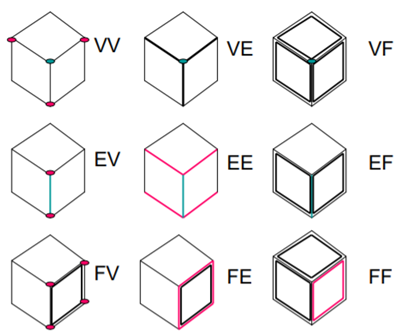
The following figure shows Adjacency Topology in B-rep

Adjacency Topology in B-rep
V represents Vertex
E represents Edge
F represents Face
Orientability and Topological Atlas
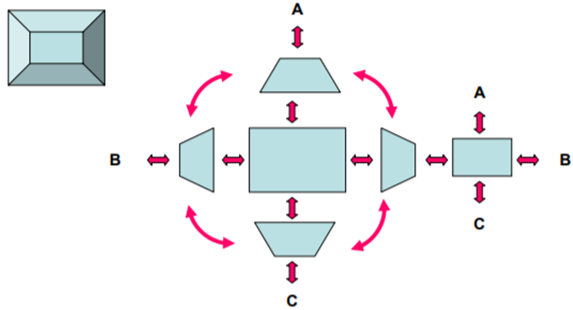
The simplest data structure keeps track of adjacent edges. This type of a data structure is known as atlas.
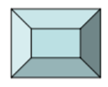
Consider a following solid model,
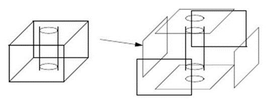
The topological atlas of the above solid model is given by,
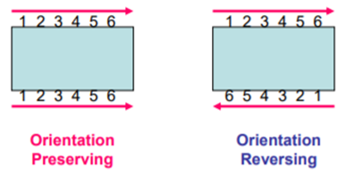
The orientability indicated with arrows or numbers as shown below. The arrows in orientation preserving are in two opposite rotational directions i.e., clockwise and anticlockwise. While orientation reversing arrows are in the same rotational directions.
B-Rep has to fulfill some of the conditions. These conditions are to disallow self-intersecting and open objects.
This condition contains –
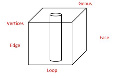
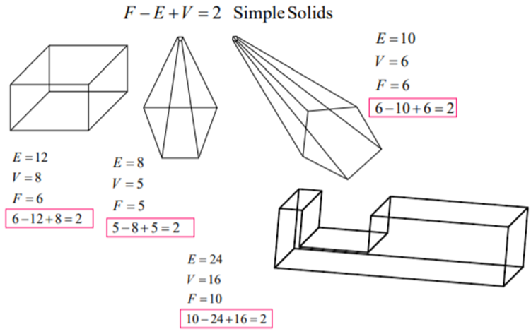
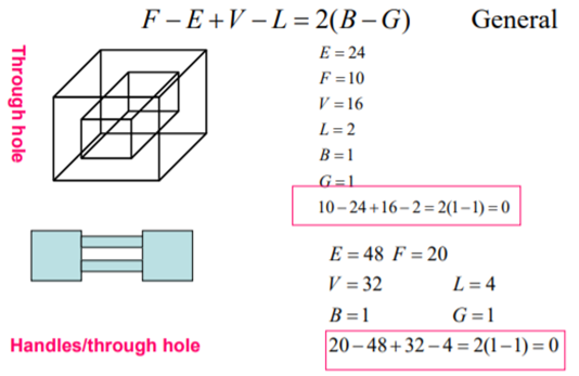
The validity of a solid is checked through the mathematical evaluation called Euler’s Formula or Euler-Poincare Law. A quantitative relationship is given by Euler-Poincare law among faces, edges, vertices, faces’ inner loops, bodies or through holes (genus) in solids.
Euler’s equation is used to verify the topological validity of Boundary representation models. The B-rep model is topologically valid only if it satisfies Euler’s equation.
Euler (1752) a Swiss mathematician had proved that homomorphic polyhedral to a sphere are topologically valid if they satisfy the equation below:
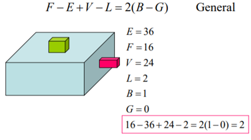
A general Euler’s equation of a 3D object is
F – E + V – L = 2(B – G)
Where,
F – number of holes in face,
E – number of edges,
V – number of vertices,
L – number of loops,
G – number of genus,
B – number of separate bodies.
Euler’s Equation for a simple 3D object (without internal void or hole, without through hole) is
F – E + V = 2
As for simple 3D object, L = 0, G = 0 and B = 1.
A general Euler’s Equation for a 2D object or open object is given as
F – E + V – L = B – G
A connected structure of vertices, edges and faces that always satisfies Euler’s formula is known as Euler object. The process that adds and deletes these boundary components is called an Euler operation.
Validity checking of some simple objects
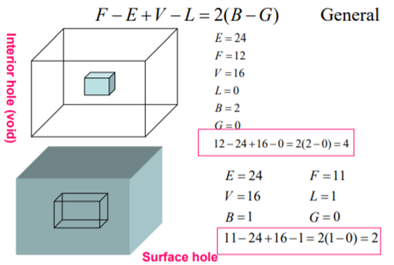
Validity Checking for Polyhedra with inner loops
Validity Checking for Polyhedra with holes
Validity Checking for Polyhedra with through holes (handles)
A constructive solid geometry is one of the most widely used approaches to create a solid object.
Faces, edges, vertices are not defined in explicit but inn implicit. Hence, CSG representation is unevaluated. Since CSG models are built from solid elements, they are always valid type of model. CSG models are always complete and unambiguous in nature.
In CSG, a combination of simpler solid objects or 3D geometric entities called as primitives generally represents objects.
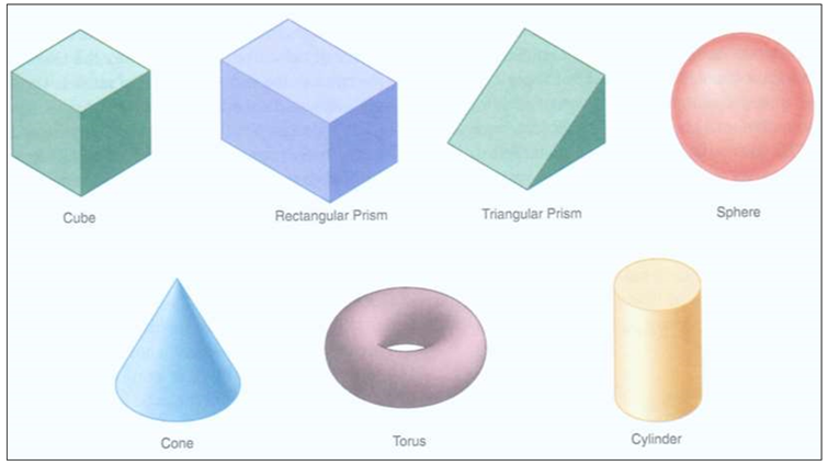
Examples of the primitives are cube, cylinder, cone, torus, sphere, etc.
Following are some primitives.
Primitives
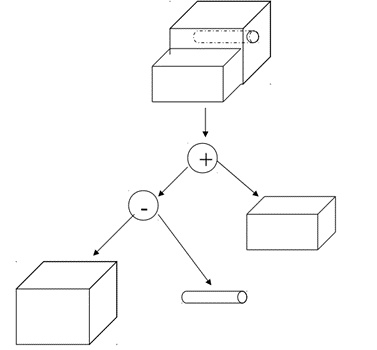
A CSG model represents that physical objects is generated by combination of primitives through specific rules called Boolean Operations. A complete creation of solid model is done by combining these “instances” logic operations referred as Boolean Operators.
Each primitive solid is thought to be a set of points, a boolean operation is carried on point sets resulting in a solid model. With the use of Boolean set of operations on two or more primitives, a desired solid geometry is resulted.
Before the boolean operation are to be performed, the relative location and orientation of the two primitives should be set.
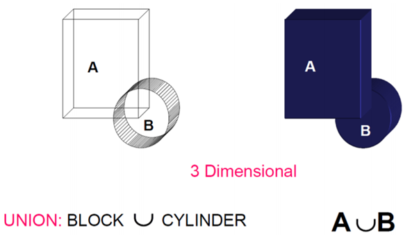
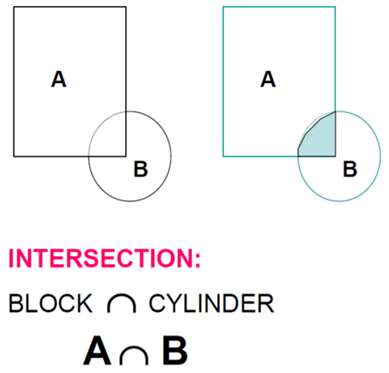
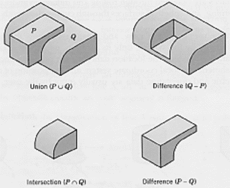
Normal Boolean operations are union, intersection and subtraction which are given below
1) Union
The Boolean Operation “Union” represents the sum of all points in each of two defined sets - (logical “OR”). Also referred to as Join, Combine, Merge, Add
2) Intersection
The Intersection Operator refers tothose points common to each of two defined sets (logical “AND”)
In Intersection, set must share common volume. Intersection is also referred to as common, conjoin.
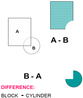
3) Difference
The Boolean Operator “Difference” represents the points in a source set minus the points common to a second set - (logical “NOT”). It is also referred to as subtraction, remove, cut.
Examples of Boolean operations:
Data Structure CSG Model - CSG Tree
Data structure implies the geometric shape through a procedural description instead of defining model shape explicitly. Example: object is not defined as a set of edges & faces but by the instruction: union primitive1 with primitive 2.
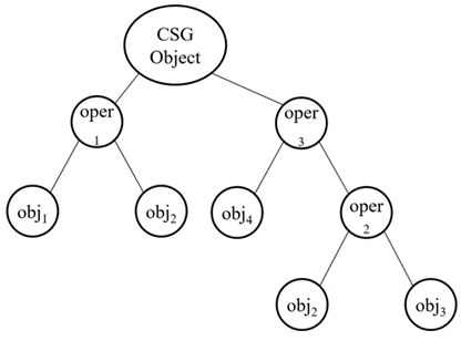
This procedural data is saved in a data structure called as CSG tree. The data structure is simple in nature. It saves easy to manage compact data. The history of applying Boolean operations on the primitives are also saved in CSG tree. In CSG data structure, data is stored in a binary tree format. The primitives are represented by the outer leaf nodes of tree. Boolean operations performed are represented by the interior nodes.
Format of CSG tree is shown below.
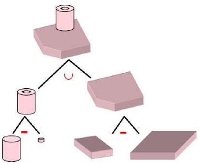
Few examples of solid model constructed in CSG are shown below with the help of CSG Tree.
In Sweep representation, a solid model of an object is created by moving a surface (or curve) along a given path.
To create the sweep solid, translation and rotational sweeping methods are used. Sweeping may also be used to detect possible interference between moving parts. Sweeping simulate and analyze material removal operations in manufacturing process.
Sweeping generates objects for B-rep and CSG type of representations. Thus, it becomes an input option in many types of representations.
There are three types of sweeps:
In a linear sweep, a surface or curve is moved in a linear or circular path.
Types of linear sweep are:
In transitional sweep, a surface or curve is moved by a given distance in space in a direction perpendicular to that plane of surface or curve. The translational sweep is also known as extrusion.
b. Rotational Sweep:
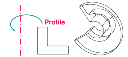
In rotational sweep, a surface or curve is rotated about an axis of rotation or axis of symmetry by a given angle.
2. Non-linear sweep
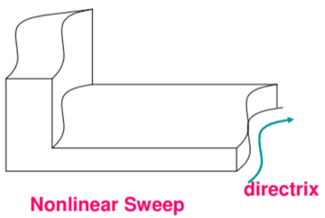
In a non-linear sweep, a surface or curve is moved along a curved path.
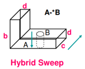
3. Hybrid Sweep
In a hybrid sweep, the two surfaces or curve are swept in two different directions and then resulting swept volume are guild together to form the object model.
In analytical modeling solid objects are described mathematically in a three-dimensional space by the parametric equations. The method is created for FEM. The ASM follows similar technique as 3-dimensional iso-parametric formulation in FEM.
E.g. 8 nodded hexahedron or a nodded polyhedron
It is mainly for design applications. It is not for manufacturing. It does not involve orientable surfaces as in B-rep and CSG.
Tensor product method is used as used in the case of surfaces. ASM solids can be referred as tri-cubic, Bezier and B-spline solids. It is analogous to bicubic, Bezier and B-spline surfaces in 2-D parametric space (u, v).
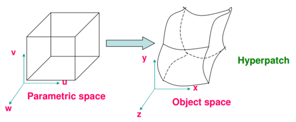
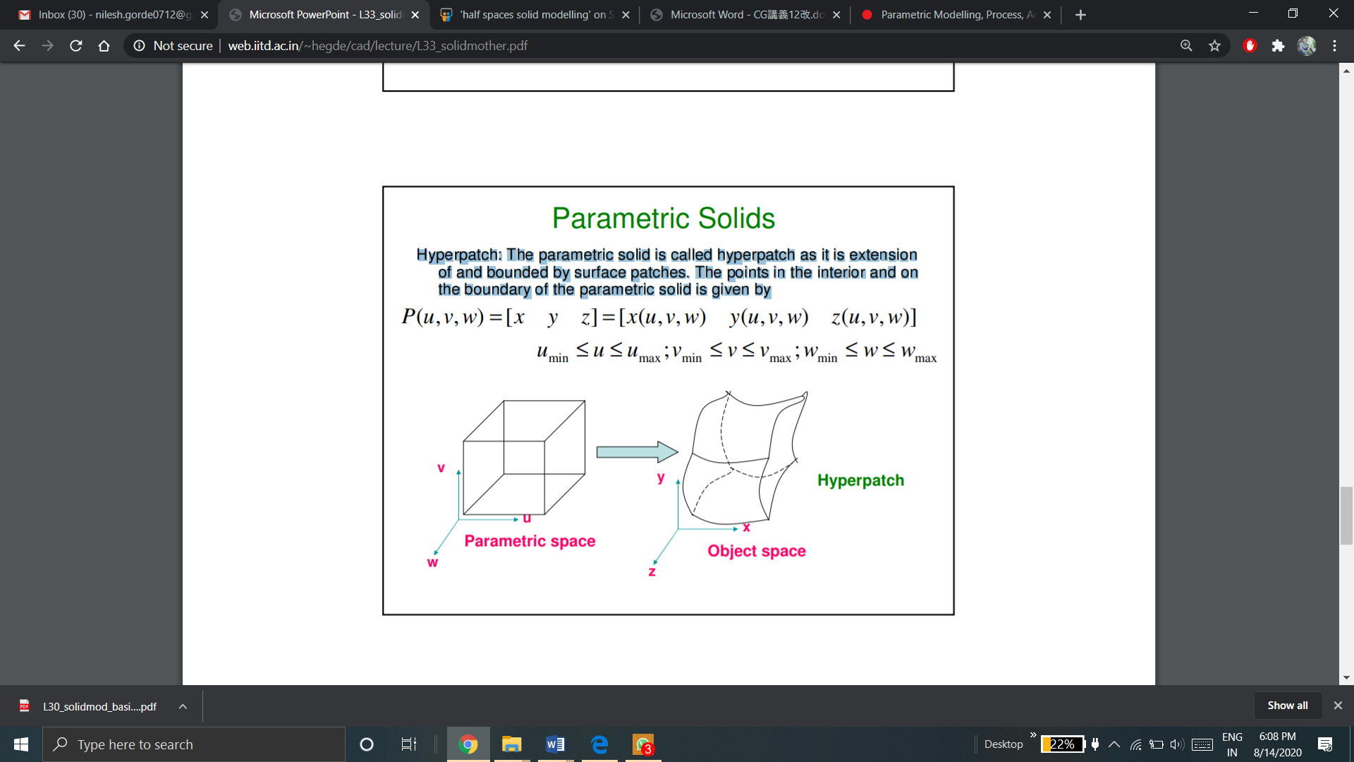
Hyperpatch: The parametric solid is referred to hyperpatch. Hyperpatch is extension of and also bounded by surface patches. The points in the interior and on the boundary of the parametric solid is given by
This hyperpatch is represented in a parametric space as a simple 3D objects as shown in the figure.
The object is partitioned into hyperpatches, in analytical modeling. The hyperpatches are shown with the use of surfaces and curves. After creation of number of hyperpatches, then these hyperpatches are assembled.
A cubic polynomial in each parameter is sufficient for most practical applications
Application of Analytical modeling:
In parametric modeling the designer models a shape by using geometric constraints and dimension data on its elements. The geometric constraints describe the relation between the elements--for example, two faces are parallel, two edges lie in a plane, a curved edge is tangent to a neighboring straight edge, and so on. The dimension data include not only the dimensions assigned on the shape but also the relations between the dimensions. These relations are provided by the designer in the form of mathematical equations. Thus, parametric modeling constructs the required shape by solving the equations that express the geometric constraints, those derived from the dimensions, and those obtained from the dimensional relations. In parametric modeling, a shape is usually constructed in the following manner.
Note that the steps in parametric modeling modify a shape through the use of geometric constraints, dimensional data, and/or dimensional relations rather than by directly modifying the shape elements. Hence the designer can generate many design alternatives without considering the details of the shape's elements and concentrate on the functional aspects of the design. The two types of parametric modeling are based on the way they solve the equations that express the geometric constraints-those derived from the dimensions, and those obtained from the dimensional relations. One type solves the equations sequentially, whereas the other type solves them simultaneously. With the former, the shape varies, depending on the sequence in which the constraints are assigned. With the latter, the same shape is obtained regardless of the sequence of the constraints but it may be in trouble when conflicting constraints are assigned.
Feature-based modeling enables the designer to model solids by using familiar shape units. A solid being created carries information about those shape units in addition to information about the elementary shape entities (vertices, edges, faces, etc.). For example, the designer can use commands such as "make a hole of a certain size at a certain place" and "make a chamfer of a certain size at a certain place," and the resulting solid will carry the information on the existence, the size, and the location of the hole and the chamfer. The shape units are called features and the modeling activity using those features is called feature-based modeling. The set of features to be provided in a solid modeling system can be determined by its most frequent applications.
Now-a-days, feature based modeling is most widely used approach of creating 3D model.
Feature is defined as the combination of shape and operation to build the parts.
Shape is a 2D sketch.
Operation is an activity that converts the sketch into a 3D shape.
Examples of feature operation are:
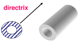
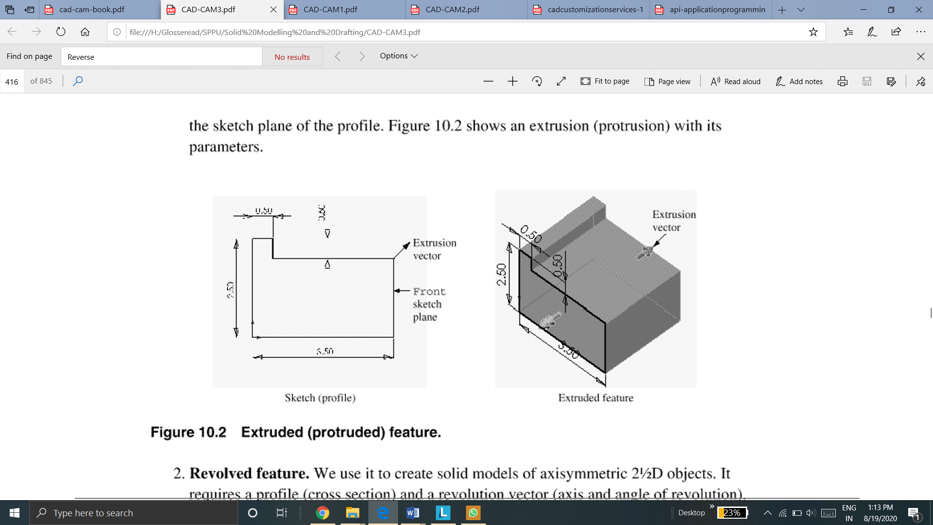
Extrude feature is used to create 2 ½ extrusion models with a uniform thickness. It requires a profile and an extrusion vector. The extrusion vector is always perpendicular to the sketch plane of profile.
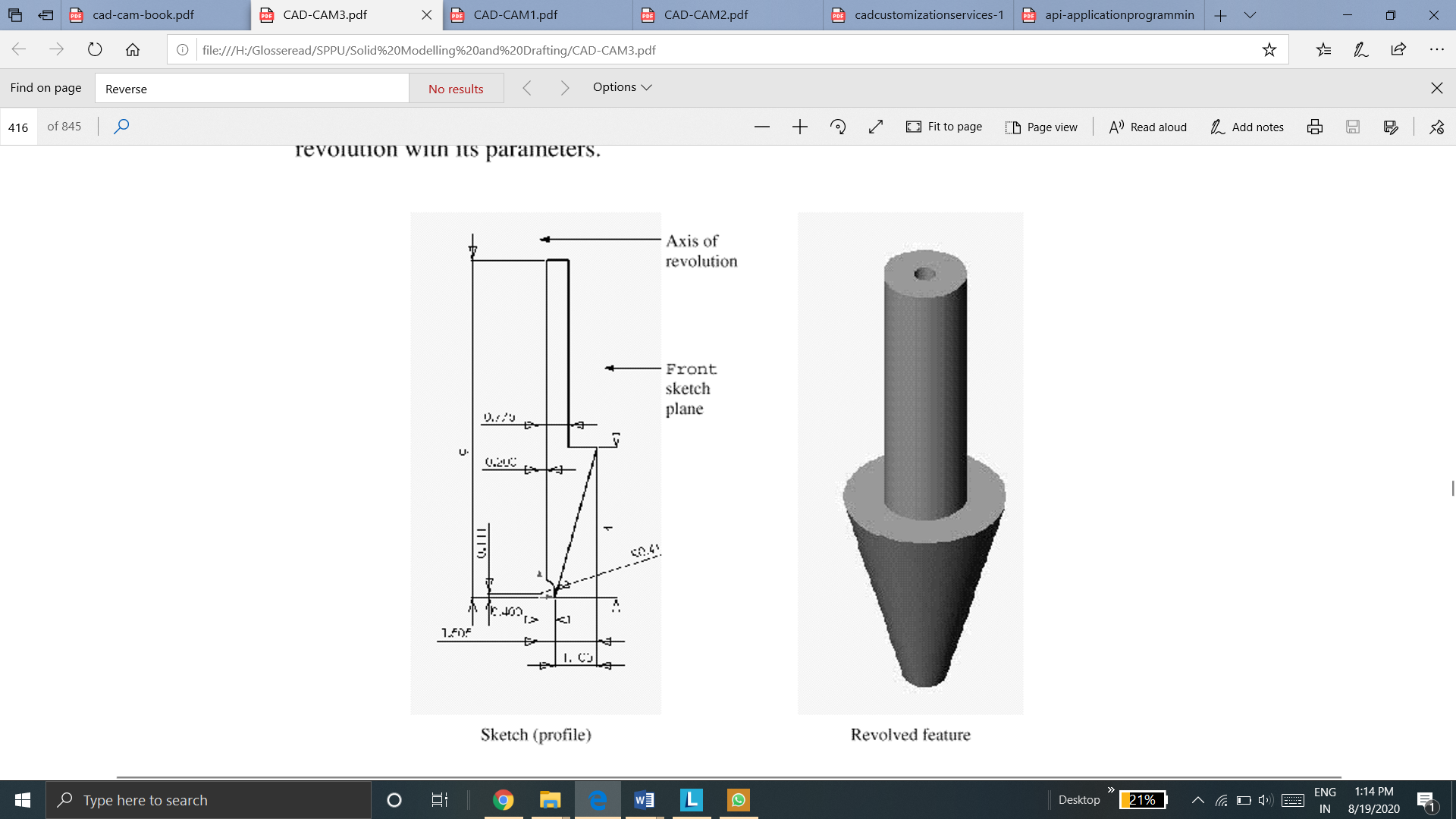
2. Revolve
Revolve feature is used to create axisymmetric objects. It requires a profile and a revolution vector (axis and angle of revolution). The axis or revolution is always in the sketch plane of the profile.
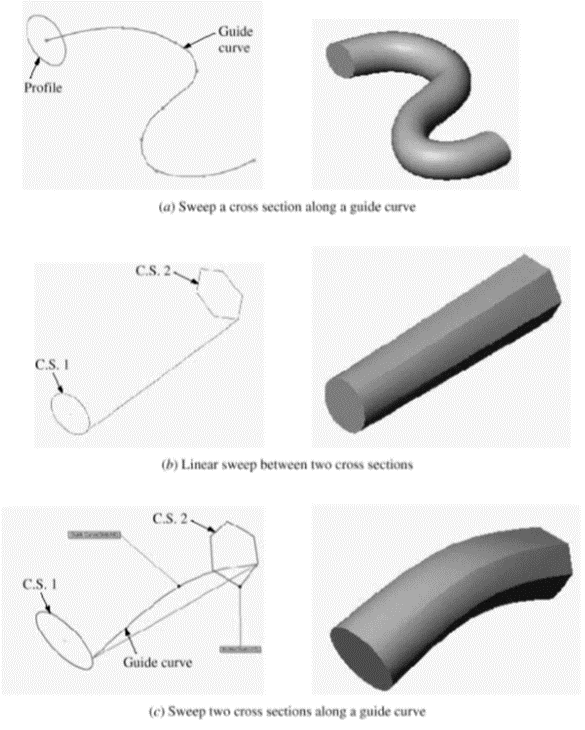
3. Sweep
Sweep feature sweeps a sketch or cross section along a guide curve. There are two types of sweeps: linear and non-linear sweeps.
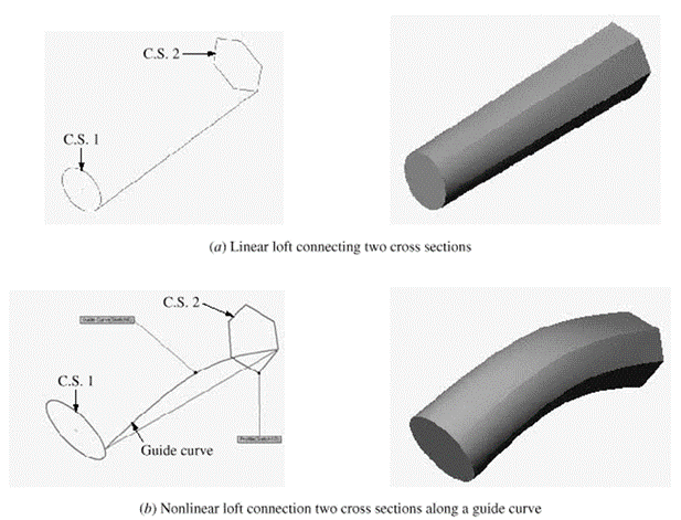
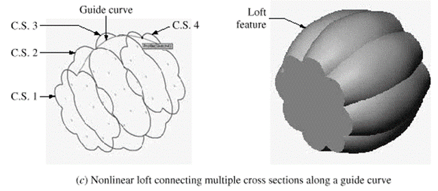
4. Loft
Loft blends multiple cross section along a guide curve to create a solid. We use loft to blend multiple cross-sections linearly along the lines connecting the corner points of the cross section are shown in fig.

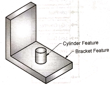
5. Boss
Boss is an addition of an extruded or revolved feature to a base feature
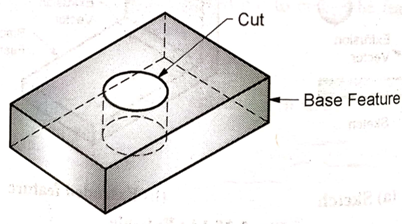
6. Cut
Cut is the subtraction of an extruded or revolved feature to a base feature.
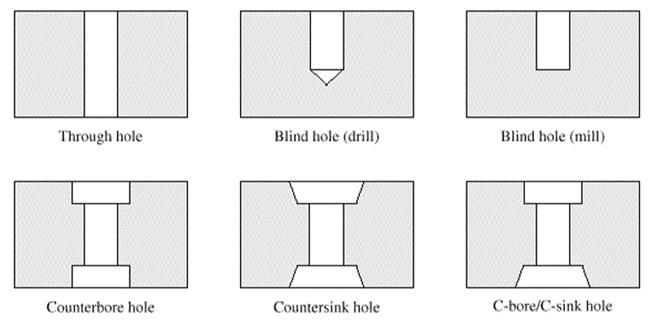
7. Hole
Hole is the subtraction of a cylinder from a solid or a base feature.
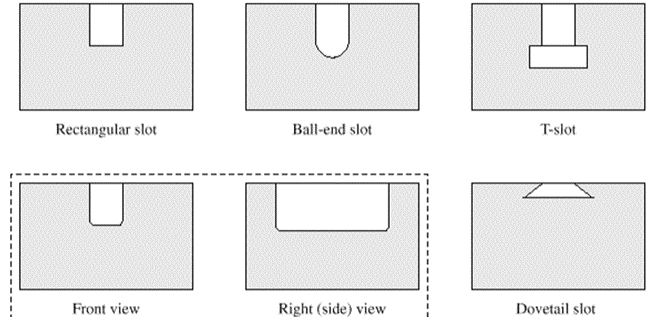
8. Slot
Slot is the subtraction of the extruded feature from a solid or a base feature.
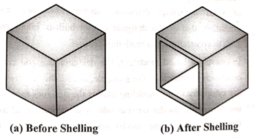
9. Shell
Shell feature is used to create a thin walled hollow solid.
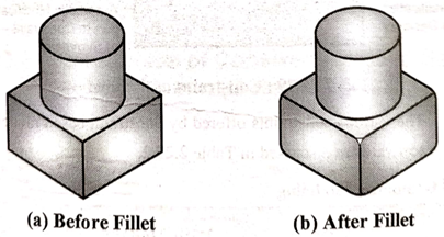
10. Fillet
Fillet is used to round off or smoothen the sharp corners and edges of the solids
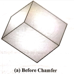
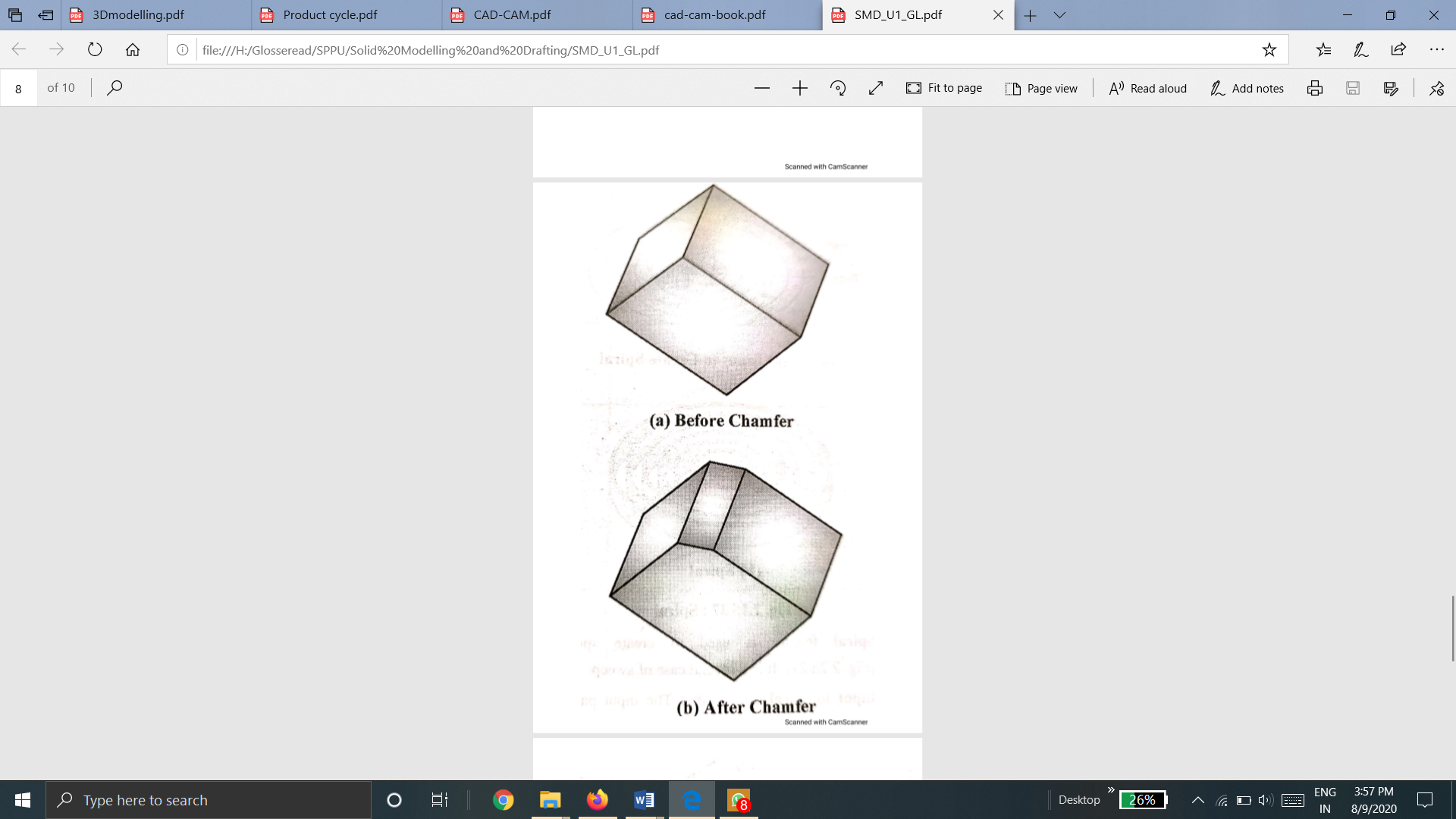
11. Chamfer
Chamfer feature is used to remove sharp edges and corners from the solid by creating beveled edges.
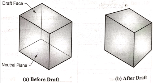
12. Draft
Draft feature is used to create taper on the surface of the object.
Steps in Feature based modeling are
First step is to create the shapes or sketches. A shape is a 2D profile or a cross-section.
ii. Create features
Apply feature operations to the sketches created in previous step. Different feature operations are extrude, revolve, sweep, loft, etc.
iii. Combine features
Different features are combined to form a 3D model.
Popular features supported by most feature-based modeling systems are manufacturing features such as chamfer, hole, fillet, slot, pocket, and so on. They are called manufacturing features because each one can be matched to a specific machining process. For example, a hole is created by drilling and a pocket by milling. Therefore, with the information on the existence, size, and location of the manufacturing features, an attempt can be made to generate process plans automatically from a solid model.
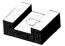
It is better to model a solid such as the one shown in Figure by using the feature commands Slot and Hole instead of by using simple Boolean operations. The solid model created by feature commands will make process planning easier, if not fully automatic.
One problem with feature-based modeling is that it cannot provide all the features necessary for many applications. As mentioned earlier, each application may require a different set of features. To get around this problem, many feature-based modeling systems provide a language in which a feature can be defined whenever it is needed. When a feature is defined, the parameters specifying the size of the feature also have to be defined. Just as primitives of various sizes could be created by assigning different values to the parameters, features can be created in many different sizes by changing parameters. Creating models of different sizes by assigning different values to the parameters is one type of parametric modeling.
Solid model database gives the detail of the distribution of solid volume in space. Through direct model query, Mass property data is obtained. If volumetric data is known, only required input is material density to calculate mass properties.
Various calculations are done in the CAD software from this mass property data. These calculations are:
Areas of individual facets are calculated – (for triangular facets, absolute value of half the cross product of two sides). The individual areas of each facets is added to get a total. This technique is typically easier for boundary representations than CSG. The answer is not exact but often within 0.5%.
2. Volume Calculation
Another main property of the solid object is volume. To calculate volume, one easy method is based upon Monte Carlo Technique.
Monte Carlo Technique:
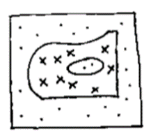
Consider a 2D example given below. Steps to calculate volume is,
In a given a 2D area, bounding box of known dimensions is generated. After randomly casting rays (vectors), area of intersection is noted.
The area is then found by multiplying the ratio of hits/total rays cast by the area of the bounding box.
This technique can be repeated in the other coordinate directions and analyzed to approximate volume.
3. Moment of Inertia
Moment of Inertia cannot be computed analytically due to complexity of geometry.
It is computed numerically through algorithms which
– divides a solid into smaller and less complex volumes (octree volumes or ray casting)
– calculates moments of smaller volumes
– sums elemental results
4. Other Calculations
Radii of gyration, products of inertia, principal axes are calculated from moment of inertia and Principal moments are calculated using principal axes and products of inertia.
Mass properties on CAD/CAM systems:
CAD/CAM systems typically calculate the mass properties. Several mass properties commands and/or modifiers exists on CAD/CAM systems calculation for 2D planar areas, 2 ½D objects, and 3D objects.
In using mass property commands, it is user’s responsibility to ensure the correctness of units of the density so the proper units for the mass and inertial properties are produced. It is also the user’s responsibility to be aware of the errors that may occur in the calculations and try to reduce these error analysis permits.
CAD systems provide users with options to control the calculations of the mass properties of CAD models. These options include the choice of measurement units for length (mm or inches) and angles (radians or degrees), the choice of decimal places, and the choice of density units.
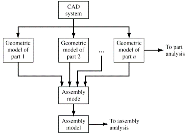
Assembly modelling is a technology and method used by CAD and product visualization computer software systems. It is used to handle multiple files which shows components within a product.
In an assembly model, in order to define a larger and complicated product representation, components are brought together. Assembly modeling is a tool that enables and lets in the collaboration amongst designers, analysis people, production people, and others in order to insure their assembly works together.
Constructing an assembly starts with bringing in a base component. It is selected due to its central role. The base component is fixed. Each component which is brought in requires to be oriented and located relative to the base or other components in the assembly. Geometric relations (constraints) are used among components to position them nicely for analysis and presentation.
Assembly
A collection of pointers to piece parts and subassemblies is referred as assembly. An assembly is a part file. That part files must include component objects.
Subassembly
A subassembly is an assembly that is used as a component object within a higher level assembly. A subassembly consists of component objects of its own.
Component Object
A component object is the entity that includes the pointer from the assembly and the master component part.
Mate
Mates are defined in a virtual assembly model for contact areas of objects in perfect situations like frictionless contacts or fully bonding relations. In actual world, the geometric mates in a virtual model is different from the mating constraints at actual physical contacts.
Various mating conditions are
Two surfaces of two different objects are made coincident with each other.
Two circular surfaces of two different objects are made concentric with each other.
Two planes of planner surfaces of two different objects are made coincident.
One planer surface is made as a tangent surface with the circular surface of another object.
Two surfaces of two different objects are made parallel with each other.
Two surfaces of two different objects are made perpendicular with each other.
Two planes from two different objects are given offset of given value.
Two surfaces are made intersecting at a given fixed edge.
Two edges are made intersecting at a given fixed point
Angles are given between two surfaces or planes.
A object is related to a specific coordinate system.
An example of a assembly with its exploded view is given below
An assembly tree with an example is shown below which shows the assembly of a pulley block
Assembly tree for pulley block assembly
There are two approaches in assembly modeling
Bottom-up approach is a logical and traditional approach of assembly modeling. It is the most common approach. The individual parts are generated independently. Then these parts are inserted into the assembly. As required by the design these parts are located and oriented (using the mating conditions). The first part which is inserted is referred as the base and is fixed.
If the parts have been already created, then this is the most preferred technique.
This approach also makes it easier to maintain the relationships of parts compared to the top-down approach.
Properties of bottom-up approach are given below:
Bottom-Up Approach
2. Top-Down Approach
In top-down type of approach, with an assembly layout sketch, firstly the assembly file is created. Here, either in the assembly file, the parts are made or the concept drawing of the parts are inserted in the assembly file and then they are finalized. Simply, before bringing them into the assembly file, the final geometry of the parts isn’t defined.
The top-down approach is perfect for huge assemblies.
Properties of Top-Down Approach
Top-Down Assembly Approach
The method of design that makes manufacturing easier of the group of parts that will form the product after assembly is referred to Design for manufacturing (DMF).
It is a tool that is used for the selection of the most cost-effective material as well as the process that can be used in the production in the product design’s early stages.
DMF is mainly used to reduce overall part production cost. It helps to minimize complexity of manufacturing operations. It uses common datum features and primary axes. It reduces overall cost by reducing material, overhead, and labor cost. DFM makes the product development cycle time as short as it can.
Principles of Design for Manufacturing
2. Design for Assembly (DFA)
The method of design of the product that is used to make assembly easier is referred to as Design for Assembly (DFA).
It is a tool that helps to assist the design teams in the design of products which will transition to productions at a less cost by focusing on the number of parts, handling and ease of assembly.
DFA is generally only reduces product assembly cost. DFA makes number of assembly operations minimum. Individual parts in DFA are said to be more complicated in design. DFA makes the material, overhead, and labor cost minimum.
The product development cycle time is shorten in DFA.
It is a requires involvement of Assembly Engineers.
Principles of Design for Assembly
3. Design for Safety (DFS)
When designing a product, it is critical to instill that design with considerations for safety. This becomes not only a sign of an experienced engineer, it is simply the right thing to do – especially in consideration of preventing accidents, injuries, and fatalities long after the design and construction phases of a project have ended. We call this Design for Safety (DFS). Because the various stakeholders in a project (architect, engineer, contractor, owner, and so forth) must interact with each other to achieve this safety objective.
It does not deal with cost reduction but with the safety of user and the product.
Principles of Design for Safety