Unit 4
Geometric Transformation
“Geometric Transformation is the change of the orientation, shape and size of the geometric model in the database and graphic image in the computer graphics.”
Transformations are the operations applied to geometrical description of an object to change its position, orientation, or size are called geometric transformations.
Any two-dimensional graphic element or object is constructed out of points. Hence, transformation of any two-dimensional graphic element essentially means the transformation of all the points of geometric entity.

Geometric Transformation
Need of Geometric Transformation
Use of Geometric Transformation
The geometric transformations are used for following purposes:
Basic Geometric Transformations:
The basic geometric transformation used in modelling in computer graphics are:
a) Translation
b) Shear
c) Rotation
d) Scaling
e) Reflection
“Translation is defined as the movement of every point on the geometric model in the same direction by same distance.”

Translation of any graphic element is translation of every points on that graphic element.
A translation moves all points in an object along the same straight-line path to new positions. The path is represented by a vector, called the translation or shift vector

Consider a point P(x, y) is translated by a distance tx in x direction and ty in y direction as shown in figure. The new point after translation is P’(x’, y’)
Coordinates of new points are given by


The above equation can be written in matrix form as


The above equation is called as the translation equation
Where,
 new position of point
 original position of point
 Translation Matrix
“A rotation is a transformation in which the object is rotated about a fixed point.”
For a positive angle, rotation is in anticlockwise direction and vice versa. The rotation of any graphic element is the rotation of all the points of that element.
In rotation, the graphic element or object is rotated about the origin or Z-axis by an angle  as shown in the figure below
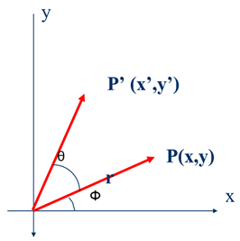
Consider a point P(x, y) is rotated about the origin (z-axis) by an angle  in anticlockwise direction as shown in figure. The new point after translation is P’(x’, y’)
Let
r = the constant distance of a point from origin
 = Original angular position of a point from horizontal.
From fig


Also,


And


From above equations we get


In matrix form we get


This is the rotation equation and
 Rotation Matrix
“A scaling transformation alters size of an object.”
Scaling changes the size of an object and involves two scale factors, Sx and Sy for the x- and y- coordinates respectively. Scales are about the origin.
Scaling is of two types:
When scaling factors are equal then the scaling is uniform scaling

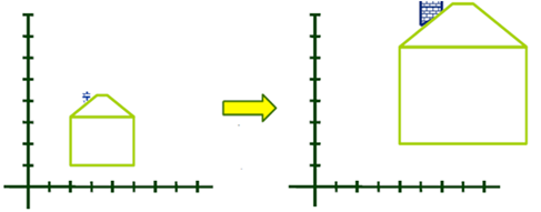
Uniform Scaling
2. Non-uniform Scaling
When scaling factors are unequal then the scaling is non-uniform scaling

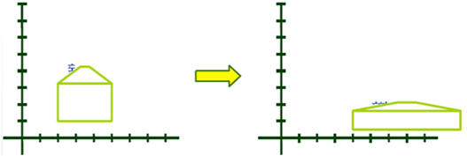
Non-Uniform Scaling
Scaling of the object is the scaling of all the points on the of that object or element.
Consider the point P (x, y) be any point on the object to be scaled and P’ (x’, y’) be the corresponding point on the scaled object.
Let
 = Scaling factor in x direction
 = Scaling factor in y direction
Therefore, the new coordinates of the point are given as


In matrix form,


This is the Scaling equation and
 Scaling Matrix
“Reflection is the transformation in which the object is flipped or reflected about a line.”
In Reflection is a transformation that produces a mirror image of a graphic element about any other axis or line. It is obtained by rotating the object by 180 deg about the reflection axis.
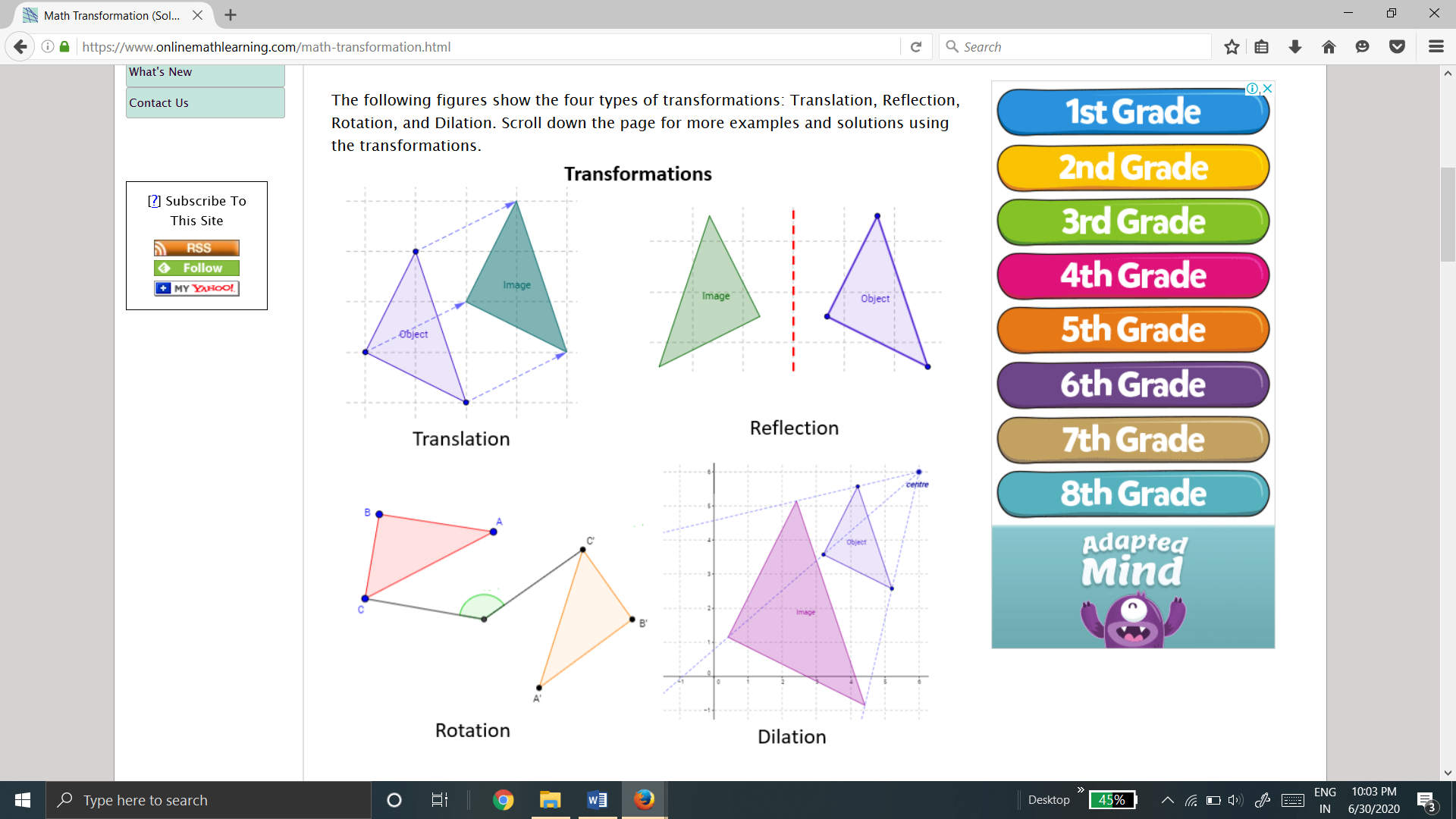
Reflection can be about various lines such as:
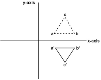
Fig. Reflection about X- axis
Consider a point P (x, y) on the object to be reflected or mirrored about x-axis and point P’ (x’, y’) be corresponding point on the reflected object.
From fig, the new coordinates are given as


In matrix form


This is the reflection equation to reflect or mirror an element about x-axis and
 Reflection Matrix or Mirror Matrix about x-axis
b. Reflection about Y- axis:
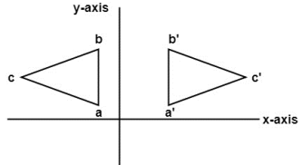
Fig. Reflection about Y- Axis
Consider a point P (x, y) on the object to be reflected or mirrored about y-axis and point P’ (x’, y’) be corresponding point on the reflected object.
From fig, the new coordinates are given as


In matrix form


This is the reflection equation to reflect or mirror an element about y-axis and
 Reflection Matrix or Mirror Matrix about y-axis
c. Reflection about origin:
Reflection about origin is nothing but reflection about both axis.
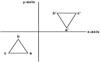
Fig. Reflection about origin
Consider a point P (x, y) on the object to be reflected or mirrored about origin and point P’ (x’, y’) be corresponding point on the reflected object.
From fig, the new coordinates are given as


In matrix form


This is the reflection equation to reflect or mirror an element about origin and
 Reflection Matrix or Mirror Matrix about origin.
d. Reflection about line y=x:
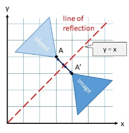
Reflection about y=x
Consider a point P (x, y) on the object to be reflected or mirrored about line y = x and point P’ (x’, y’) be corresponding point on the reflected object.
From fig, the new coordinates are given as


In matrix form


This is the reflection equation to reflect or mirror an element about line y = x and
 Reflection Matrix or Mirror Matrix about y = x
e. Reflection about line y=-x:
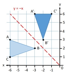
Fig. Reflection about y=-x
Consider a point P (x, y) on the object to be reflected or mirrored about line y = -x and point P’ (x’, y’) be corresponding point on the reflected object.
From fig, the new coordinates are given as


In matrix form


This is the reflection equation to reflect or mirror an element about line y = -x and
 Reflection Matrix or Mirror Matrix about line y = -x
“A transformation in which all points along a given line remain fixed while other points are shifted parallel to by a distance proportional to their perpendicular distance is shear transformation.”
A shear transformation distorts the shape of the graphic element or object such that the distorted shape appears as if the object were composed of internal layers that had been caused to slide over each other.
Shearing of object consists of linearly deforming it along either x-axis or y-axis or both.
Types of shear:
a) X – direction shear:
X shear shifts the coordinate x values.
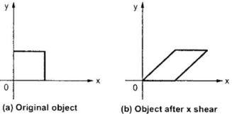
Fig. X – direction shear of graphic element
Consider a point P (x, y) on the object which is subjected to shear in x-direction to occupy a new position P’ (x’, y’)
From fig, the new coordinates are given as


Where  shear parameter in x-direction
In matrix form


This is the X-direction shear equation and
 X-direction Shear Matrix
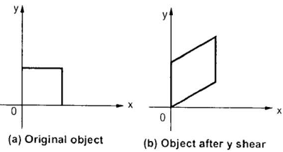
b) Y – direction shear:
Y shear shifts the coordinate y values
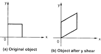
Fig. Y– direction shear of graphic element
Consider a point P (x, y) on the object which is subjected to shear in y-direction to occupy a new position P’ (x’, y’)
From fig, the new coordinates are given as


Where  shear parameter in y-direction
In matrix form


This is the Y-direction shear equation and
 X-direction Shear Matrix
The rotation of a point, straight line or an entire image on the screen, about a point other than origin, is achieved by first moving the image until the point of rotation occupies the origin, then performing rotation, then finally moving the image to its original position.
The moving of an image from one place to another in a straight line is called a translation. A translation may be done by adding or subtracting to each point, the amount, by which picture is required to be shifted.
Translation of point by the change of coordinate cannot be combined with other transformation by using simple matrix application. Such a combination is essential if we wish to rotate an image about a point other than origin by translation, rotation and again translation.
To combine these three transformations into a single transformation, homogeneous coordinates are used. In homogeneous coordinate system, two-dimensional coordinate positions (x, y) are represented by triple-coordinates.
Homogeneous coordinates are generally used in design and construction applications. Here we perform translations, rotations, scaling to fit the picture into proper position.
To convert the coordinates of a 2D graphic element into homogeneous coordinates, the original coordinates are multiplied by a homogeneous parameter ‘h’ and the third coordinate is added whose value is the same parameter ‘h’.
Mathematically,

Where,

Hence, any 2 x 2 transformation matrix in two-dimensional cartesian system are modified to 3 x 3 transformation matrix in homogeneous coordinate system.
Example of representing coordinates into a homogeneous coordinate system:
For two-dimensional geometric transformation, we can choose homogeneous parameter h to any non-zero value. For our convenience take it as one. Each two-dimensional position is then represented with homogeneous coordinates (x, y, 1).
Let P (x, y, 1) be the original point of any graphic element in homogeneous coordinate system.
After performing certain transformation, new coordinates of point P is P’ (x’, y’, 1)
We can write the transformation equation as


Where,
 Homogeneous transformation matrix.
The transformation equation and transformation matrix of basic 2D geometric transformation in homogeneous co-ordinate system are:
The translation equation is

Homogeneous Translation Matrix is

2. Rotation
The rotation equation is

Homogeneous Rotation Matrix is

3. Scaling
The scaling equation is

Homogeneous Scaling Matrix is

4. Reflection
The reflection or mirror equation to reflect about x-axis is

Homogeneous Reflection or Mirror Matrix about x-axis is

b. Reflection about y-axis
The reflection or mirror equation to reflect about y-axis is

Homogeneous Reflection or Mirror Matrix about y-axis is

c. Reflection about origin
The reflection or mirror equation to reflect about origin is

Homogeneous Reflection or Mirror Matrix about origin is

d. Reflection about line y = x
The reflection or mirror equation to reflect about line y = x is

Homogeneous Reflection or Mirror Matrix about line y = x is

e. Reflection about line y = -x
The reflection or mirror equation to reflect about line y = -x is

Homogeneous Reflection or Mirror Matrix about line y = -x is

5. Shear
The shear equation in X-direction is

Homogeneous Shear Matrix in X-direction is

b. Y-direction shear
The shear equation in Y-direction is

Homogeneous Shear Matrix in Y-direction is

“These are also called as opposite transformations.”
If T is a translation matrix than inverse translation is representing using T-1. The inverse matrix is achieved using the opposite sign.
During the development of composite transformation matrix, many a times, it is necessary to use the inverse of some basic geometric transformation matrices.
Various Inverse Transformation matrices for various 2D Inverse geometric transformations are:
The inverse translation matrix is obtained by replacing the translation parameters  and
and  with
with  and
and  respectively in translation matrix.
Therefore, inverse translation matrix is given as

2. Inverse Rotation
The inverse rotation is obtained by the rotation parameter  with
with  in rotation matrix.
If rotation matrix rotates the graphic element in anticlockwise direction then inverse rotation rotates the graphic element in clockwise direction.
Therefore, the inverse rotation matrix is


3. Inverse Scaling
The Inverse scaling matrix is obtained by replacing the scaling parameters  and
and  with
with  and
and  respectively in scaling matrix.
If Scaling matrix increases the size of the graphic element, then inverse scaling matrix reduces the size of graphic element.
Therefore, inverse scaling matrix is given by

4. Inverse Reflection
The inverse reflection matrix is same as that of the reflection matrix.
Therefore,


A number of transformations or sequence of transformations can be combined into single one called as composition. The resulting matrix is called as composite matrix. The process of combining is called as concatenation.
A concatenated transformation is the combination of two or more transformation such as: translation, rotation, scaling and reflection. A single transformation matrix, known as composite matrix or concatenated matrix can be obtained from such combination of transformations. This helps to improve the performance of graphic package.
The concatenated transformation of any graphic element is the concatenated transformation of all the points on that element.
Suppose we want to perform rotation about an arbitrary point, then we can perform it by the sequence of three transformations
The ordering sequence of these numbers of transformations must not be changed. The composite transformation is performed by multiplying matrix in order from right to left side.
Example showing composite transformations:
The enlargement is with respect to center. For this following sequence of transformations will be performed and all will be combined to a single one
Step1: The object is kept at its position as in fig (a)
Step2: The object is translated so that its center coincides with the origin as in fig (b)
Step3: Scaling of an object by keeping the object at origin is done in fig (c)
Step4: Again translation is done. This second translation is called a reverse translation. It will position the object at the origin location.
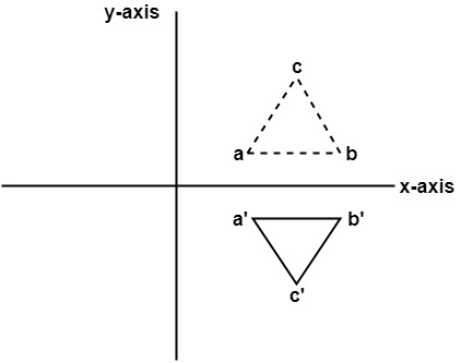
Mathematical representation of the composite transformation for the above example:
In the above example object is first translated.
Therefore, translation matrix is given by

Let (a, b) be the centroid of the object(triangle)
In this case,


As the object is translated so that its centroid coincides with origin.

In the second step, the object is scaled by parameters Sx and Sy.
The scaling matrix is given by

And finally, the object is again translated back to its original position. It becomes an inverse translation
Inverse Translation matrix is given by

But


The concatenated transformation matrix is


And the transformation equation is

General Pivot Point Rotation or Rotation about Fixed Point:
1) For it first of all rotate function is used. Sequences of steps are given below for rotating an object about origin.
2) Translate object to origin from its original position as shown in fig (b)
3) Rotate the object about the origin as shown in fig (c).
4) Translate the object to its original position from origin. It is called as reverse translation as shown in fig (d).

In the above case, Object is first translated such that the center of object coincides with the origin. Then the object is rotated about and angle  and again translated to its original place.
In this case, concatenated matrix is


The two basic tasks required to display an image of an object on a graphics device are: (I) specifying the location of all the points on the object in space, and (2) determining which locations on the display monitor are to be occupied by those points. Thus, a coordinate system is necessary to provide a reference for specifying the location of a point both in space and on the monitor.
In CAD modeling it is often required to transform the objects from one coordinate system to another.
There are three major types of coordinate system commonly used in CAD modeling.
“The model coordinate system is the reference space of model with respect to which all the geometrical data of model is stored in database.”
This is the only coordinate system that modelling software recognizes when storing or retrieving the graphical information in or from model database.
The CAD software stores the graphical information in the model database with reference to the coordinate system known as model coordinate system.
The world coordinate system is a reference coordinate system used to describe what the world of interest looks like, as its name implies (i.e., what types of objects exist in the world and how they are located). For example, this system can be used to describe the locations and orientations of desks, chairs, and the blackboard if the world in which we have an interest is a classroom.
2. User Coordinate System (UCS) or Local Coordinate System or Working Coordinate System (WCS):
Now, to describe the shape of each object in that world. The shape of an object is defined by the coordinates of all the points or some characteristic points on the object with respect to a coordinate system attached to the object. This coordinate system is called the model coordinate system
“User Coordinate System is defined by the user for the convenience of input of the graphical information.”
In CAD modelling, the user inputs the graphical information with reference to the coordinate system known as user coordinate system.
If the geometric model has a complex geometry or a specific orientation, it is highly inconvenient to input the graphical data in a model coordinate system.
Figure below explains the difference between model coordinate system and local coordinate system.
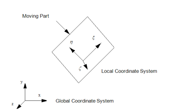
Model and User coordinate system
3. Screen Coordinate system:
“Screen Coordinate system is a 2D Cartesian Coordinate System whose origin is located at the corner of the graphics display screen.”
This 2D coordinate system refers to the physical coordinates of the pixels on the computer screen, based on current screen resolution.
This system is display-device dependent. The coordinate system of the screen is a cartesian coordinate system. The origin (0,0) is at the top left of the screen. Positive x increases toward the right and positive y increases toward the bottom.
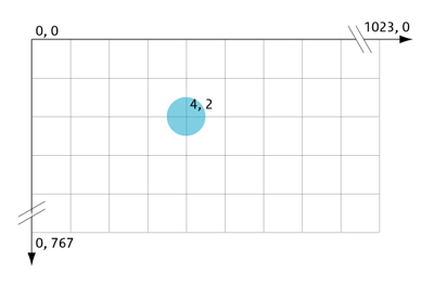
Fig. Screen Coordinate System
“Mapping of the Geometric model changes the graphical description of model from one coordinate system to another without changing the position, orientation, size and shape of the model.”
In CAD modelling, the user inputs the graphical information with reference to the working or user coordinate system (UCS or WCS) of the sketch plane, while CAD software stores the graphical information in the model database with reference to Model Coordinate System (MCS).
The modeling software needs to convert the graphical information from one coordinate system to another coordinate system. Mapping of geometric model changes the graphical description of model from one coordinate system to another without changing the position, orientation, size and shape of the model.
Just like geometric transformations, mapping also plays central role in geometric modeling. The geometric mapping is used in modeling, analysis, animation, etc.
Mapping is used to convert the coordinates of points on the model from one coordinate system to another.
Types of Geometric Mapping:
“If the axes of the two coordinate systems are parallel, then the mapping is called translation mapping.”

Let, dx = distance of the origin of original system (O) from the origin of the new coordinate system (O’) along X-direction.
dy = distance of the origin of original system (O) from the origin of the new coordinate system (O’) along Y-direction.
Coordinate of point P in new coordinate system are:
x’ = x + dx
y’ = y + dy
The above equation in matrix form can be written as

Or

Where,
 Coordinates of point P in original coordinate system X-Y
 Coordinates of point P in new coordinate system X’-Y’
 Translational mapping matrix
2. Rotational Mapping:
“If both the coordinate systems have common origin but the axes are at an angle, then the mapping is called rotational mapping.”
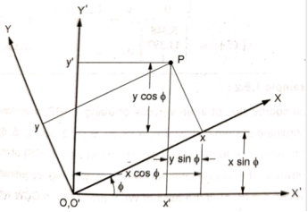
Let, ɸ = angle made by the axes of original coordinate system with the axes of new coordinate system.
Coordinate of point P in new coordinate system are:
x’ = x cos ɸ - y sin ɸ
y' = x sin ɸ + y cos ɸ
The above equation in matrix form can be written as

Or

Where,
 Coordinates of point P in original coordinate system X-Y
 Coordinates of point P in new coordinate system X’-Y’
 Rotational mapping matrix
3. General Mapping:
“It is the combination of rotational and translational mapping.”
If both the coordinate systems don’t have common origin and the axes are at an angle, then the mapping is called general mapping.
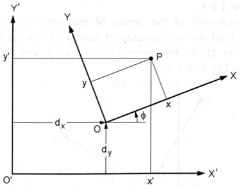
Let, dx = distance of the origin of original system (O) from the origin of the new coordinate system (O’) along X-direction.
dy = distance of the origin of original system (O) from the origin of the new coordinate system (O’) along Y-direction.
ɸ = angle made by the axes of original coordinate system with the axes of new coordinate system.
Coordinate of point P in new coordinate system are:
x’ = x cos ɸ - y sin ɸ + dx
y' = x sin ɸ + y cos ɸ + dy
The above equation in matrix form can be written as

Or

Where,
 Coordinates of point P in original coordinate system X-Y
 Coordinates of point P in new coordinate system X’-Y’
 General mapping matrix
“It is the process of converting a 3D object into a 2D object.”
It is also defined as mapping or transformation of the object in projection plane or view plane. The view plane is displayed surface.
Terminologies used in projection:
Center of projection
The center of projection is a view point from where all the projection rays start.
Projectors
The projectors are the projection rays used for obtaining the projection of an object.
Projection plane
The projection plane is the plane on which the two-dimensional image of an object is obtained.
Based on the position of center of projection with reference to the projection plane, the methods of projection are broadly classified into two types:
If the center of projection is at infinite distance from the projection pane, all the projections are parallel to each other. Such method of projection is called as parallel projection.
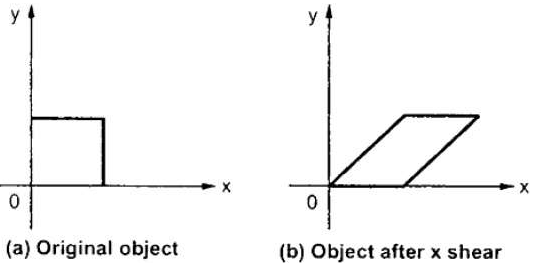
Fig. Parallel projection
In order to display picture that is in its true shape and size, Parallel Projection is used.
From each vertex on the object, by extending parallel lines until they intersect the plane of the screen, the parallel projection is formed. The projection of vertex is nothing but the the point of intersection.
Parallel projections are utilized by architects and engineers for making working drawing of the object. For complete representations, using different planes, requires two or more than two views of an object. The parallel projection method is used in drafting; to produce the front, the top and the side view of an object.
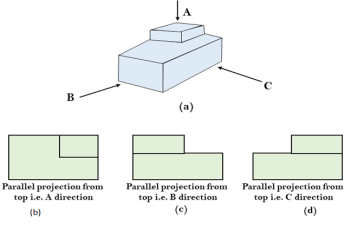
The parallel projection are further classified into two types:
In orthographic type of projection all the projectors are parallel to each other as well as perpendicular to projection plane.
In this method of projection, one of the principal axes of MCS of the object is perpendicular to the projection plane, while remaining two principal axes are parallel to the projection plane.
Orthographic projection
b. Axonometric or oblique projection
In axonometric projection all the projectors are parallel to each other and inclined to projection plane.
In this method of projection, the principal axes of MCS of the object are inclined to the projection plane. Therefore, axonometric projection shows several faces of model at one glance.

Axonometric projection
Some of the axonometric projections are
Dimetric: In these two projectors have equal angles with respect to two principle axes.
Trimetric: The direction of projection makes unequal angle with their principle axes in dimetric projection.
But the most commonly used axonometric projection is an isometric projection.
Isometric projection
In isometric projection, the projection planes intersect each principal axis of MCS of the object at the same distance from the origin. All projectors make equal angles generally angle is of 30°.

Isometric projection
2. Perspective Projection:
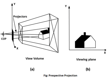
If the center of projection is at finite distance from the projection plane, all the projectors meet at the center of projection and they are non-parallel. Such a method of projection is called perspective projection.

Fig. Perspective projection
In perspective projection, farther away the object from the viewer is, smaller it appears. This property of projection tells us about depth. To drawing three-dimensional scenes, artist generally use perspective projection.
Vanishing points and perspective foreshortening are the two important characteristics of perspective projection. Because of foreshortening object, the lengths looks smaller from the center of projection. By increasing the distance from the center of projection, object will appear smaller.
The perspective projection helps in adding an artistic effect and enhancing realism to the projected view.
Vanishing Point:
“Vanishing point is the point where all lines looks that they meet. There may be one point, two point or three-point perspective projections.”
One Point:
“When there is only one vanishing point, it is one-point perspective”
Two Points:
“When there are two vanishing points then it is two-point perspective. One point is in the x-direction and another point is in the y –direction.”
Three Points:
“When there are three vanishing points then it is referred to three-pint perspective. First is in x-direction, second in y-direction and third in 2 directions.”
In Perspective projection lines of projection are not parallel but they coincide. The lines converge at a single point called a center of projection. The projected image on the screen is obtained by points of intersection of converging lines with the plane of the screen. The image on the screen is seen as of viewer's eye were located at the center of projection, lines of projection would correspond to path travel by light beam originating from object.
Drawing of a 3D model is an important part in designing process. In order to understand the idea, it is very important to represent it on paper. Projection of planes plays an important role in engineering drawing of any engineering model.
Architects and engineers use various plans, sections and elevation to depict designs and detail constructions of objects. Designers often use remote manufacturing, in an attempt to keep cost low. Designers also produce working drawings so that prototypes can be manufactured. This leads to improvements being made to the product. These working drawings are generally made on a CAD software, but skilled workers still prefer to draw it by hand. Designers find sketching in orthographic projection very useful.
Isometric projection gives more detail of the product. Hence designers also find isometric projection more useful. It shows exactly how the product or model will exactly look like.
The perspective projection helps in adding an artistic effect and enhancing realism to the projected view.