Unit 5
CAD Data Exchange
In CAD system, component database is the heart of the CAD model. Component database contains the graphics entities such as points, lines, arcs, curves, circles etc. Along with graphic entities it also includes the co-ordinate points that define the location of these entities. In all downstream applications of CAD that contains finite element modeling and analysis, process planning, estimation, CNC programming, robot programming, programming of co-ordinate measuring machines, ERP system programming and simulation, this geometric data is used. In order to achieve at least a reasonably high level of integration between CAD, analysis and manufacturing operations, the component database must contain:
In designing a data structure for CAD database the following factors are to be considered:
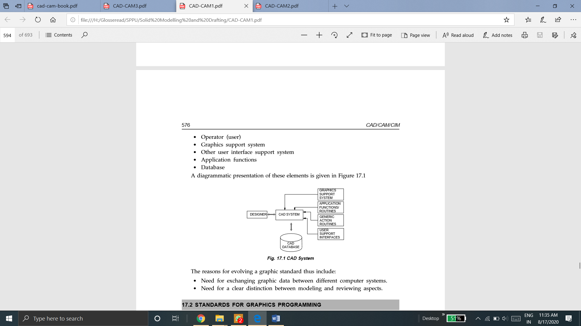
In order to achieve the above requirements, some type of standardization has to be followed by the CAD software designers. The elementary elements connected to a CAD system are:
A diagrammatic presentation of these elements is given in Figure
Need for CAD Data Exchange
Design projects requires data to be shared between suppliers and designers. Different CAD systems are generally used by different companies. All CAD systems contains their own formats of database. So, in order to share these data, the CAD data must be exchanged from one format to another. These database formats are generally confidential and also proprietary. For this reason, data conversion between systems becomes necessary. The exchange or conversion of CAD data from one format to another format is called as CAD data exchange.
For example, consider one company develops a CAD model while another performs analysis work on the same model. At the same time a third company takes responsibility of manufacturing the product. The CAD systems available in market usually are different in their application aims, user interfaces and performance levels. They also differ in data structures and data formats. Hence, accuracy in the data exchange process is very important. This is the reason that robust exchange mechanisms are required.
Other reasons for the need of CAD Data Exchange are:
The kernel is the heart of a CAD system. It is also referred as solid modeling kernel or geometric modeling kernel. The code that determines that how the image one can see on the screen is actually described with math is referred to Kernel. As descrption of manufacturable shapes in a mathematical representation includes making choices of how each shape can be calculated and can be stored, Hence this becomes of upmost importance. A geometric modeling kernel is referred to a 3D modeling component that is found in modeling software. Example of these modeling softwares are computer-aided design (CAD). It is impossible to produce the images that one can on the screen without the kernel.
Graphical Kernel System is an ANSI as well as ISO standard. It standardizes 2D graphics functionality at a relatively low level. The basic purposes of these standard are:
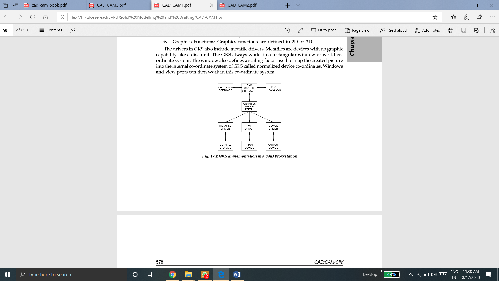
Figure shows the GKS implementation in a CAD workstation. The features of GKS include:
In GKS, the drivers consist of metafile drivers. The devices which don’t have graphic capability like a disc unit are Metafiles. The Graphics Kernel System continually works in a rectangular window or WCS. The window represents a scaling factor into the internal co-ordinate system of GKS that is used mapping of the created picture known as normalized device co-ordinates. Windows and view ports may work in this type of normalized co-ordinate system.
GKS offers two outlines to define the user created pictures. They are primitive functions and attribute functions.
Examples of primitive functions are:
The appearance of the image is defined by attribute functions.
e.g. color, line-type etc.
In every CAD package data is stored internally in a format that is well suited for that particular package. When the user finishes its work, then on the hard drive, this data is written into files. These proprietary formats are possible to read by only the specific program. These are of no use to other programs.
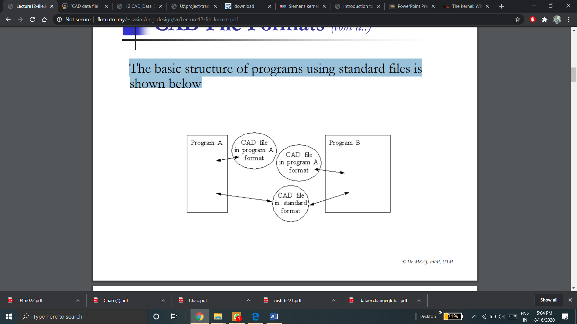
For most present-day engineering applications, it is important to transfer CAD models between different computer programs. Between dissimilar programs, the best method for storing and transferring CAD geometries are Standard file formats. Files are generally stored on disks as ASCII or binary file format with a structure that agrees upon by organizations which represents different interest groups in the CAD or CAM sectors. When these standard formats are used data can be easily transported between any systems. But some vendors do not conform fully to these standards.
The basic structure of programs using standard files is shown below
Although initially targeted for the geometric data of a product, today it is able to retrieve other pieces of information from a CAD file:
The various types of product information that are targeted by the exchange process varies over the life cycle of the product. More emphasis is offered to the geometric and design intent aspects of the data exchange at earl stages of the design process. Whereas metadata and application data are necessary at after stages of the product and process development.
Various Types of CAD data are:
Shape data: both geometric and topological information, part or form features. Fonts, color, annotation are the part of the geometric data.
Non-shape data: Non-shape data includes graphics data like shaded images, and model global data. These are measuring units of the database and the resolution of storing the database numerical values.
Design data: Design data includes information which designers create from geometric models for analysis purposes. It also includes Mass property and finite element mesh data.
Manufacturing data: Manufacturing data includes information as tooling, NC tool paths, tolerancing, process planning, tool design, and BOM.
It is the property that enables the unstopped sharing of resources between different systems. Data interoperability refers to the ability to share data between different components or machines. It is done via software and hardware. It can also be referred as the exchange of data and resources between various computers by local area networks (LANs) or wide area networks (WANs). In other words, interoperability is the ability of two or more components or systems that exchanges information as well as makes use of the information which is exchanged.
Data interoperability can also be defined as the ability of a system, software or product to exchange and make use of information with other systems, software or products. This exchange of data is without special effort on the part of the user. Two systems must be able to exchange data and subsequently present that data in the way that it can be understood by any user, to be interoperable.
Simply, Data Interoperability is the exchange and representation of data or information.
Data Interoperability
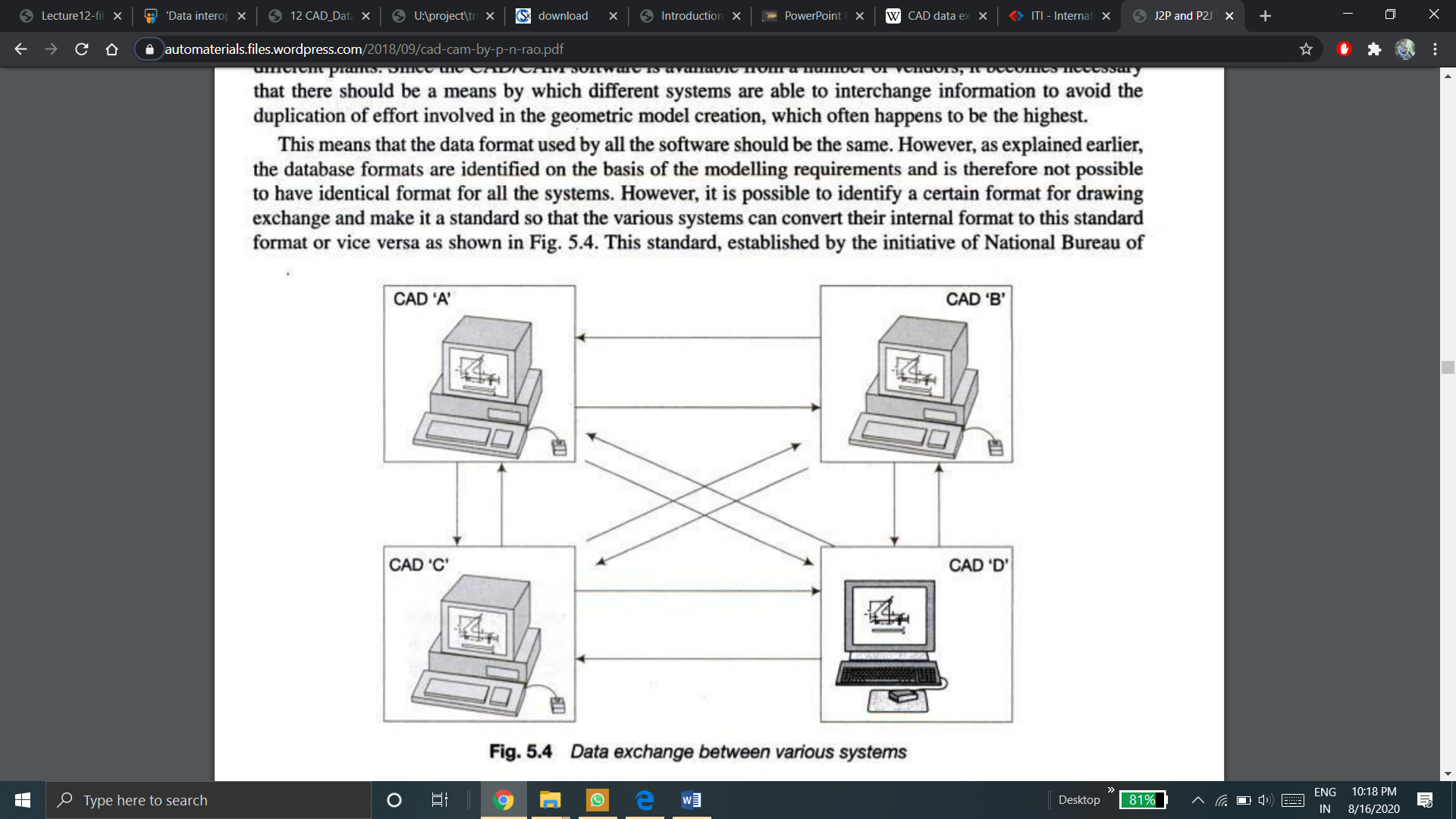
In order to exchange the data, the data format used by all the software should be same. However, the data formats are identified on the basis of modeling requirements and is therefore is not possible to have identical formats for all the system. However, one can identify certain format for drawing exchange and can make it standard. It makes possible for various system to convert their internal format to this standard format or vice versa.
The different internal mathematical representation schemes is the most critical problems in data interoperability. The internal accuracy of the geometric definitions in the modeling kernel of the various CAD systems is also one of the most critical problems in data interoperability. In particular, the trouble rises up from the accuracy and the convergence standard used when performing calculations with curves and surfaces. All this will arise within the original system or it can arise during the pre-processing and post-processing phases of CAD data. It is performed with neutral format such as IGES or STEP.
Interoperability problems has origin from many aspects associated to the modeling practices, to the various modeling core of every CAD system as well as to a less implementation of the pre-processing interface for neutral translation formats. Poor modeling practices bring about bad geometry within the originating system, that’s regularly the cause of poor data exchange. Efforts to use proven modeling techniques must be encouraged at the source.
To convert or migrate data from various distinct platforms, CAD data conversion is performed. Then data is unified under one common platform.
CAD data conversion helps an organization to keep its vendors and dealers updated about the latest improvisations of design. CAD migration is the best way to keep them updated with seamless flow of technical data and resources if the internal teams are working on a given project. CAD exchange helps engineering and product-design teams to manage effectively that too in the most complex product development which includes many design configurations.
Aspects for CAD data conversion
There are key aspects that are essential and to be considered while performing CAD conversion from one system to another:
1. Migrate new products only:
Migration of new product refers retaining all existing information in the old CAD systems. It is feasible when changes to old product lines are not common else new products are fully new. It isn’t a that safe approach as it has modeled parts as well as it is suitable when the opportunity comes up to reprocess earlier designed parts.
2. Migrate Products on the go as required:
This type of aspect is less strategic than a default one. It results in taking no time to focus on existing business goals. Is not an effective methodology irrespective whether it is feasible or not. It generally results in
- Ineffective use of technical team which should have to focus on development of new product instead of lowering component conversion.
- Product development disruptions which also results in late to market arrival.
3. Migrate Targeted Product Lines, and Projects
It is lucrative to migrate the product lines which give the best value on the investment after revising the conversion charges and the price of existing data. Focusing on long-term benefits generally shows constructive results.
4. Migrate a Percentage of the Product Line
This type of approach targets some amount of percentage of products which are chosen for their price. It converts a percentage of the product line which enables one to focus on broader picture. This strategy is an effective approach to get the maximum out of the conversion process.
5. Migrate based on sales volume of a product
To identify which product portfolios should be chosen to convert, the continuous accumulation of huge legacy information makes difficult. In such cases, the history of sales helps to determine the correct products that may be a good bargain upon conversion and would result the ROI.
Types of Data Conversion methods
There are three main methods of data conversion.
Direct data translators offer a direct solution that entails translating the information that is stored in a product database from one CAD system format to another that too in generally one step.
2. Neutral File Exchange
An intermediary neutral format is used in Neutral file exchange to translate data among CAD systems. This approach begins from a pre-processor that is embedded in the original CAD system. This generates the neutral file from the originating CAD format. The CAD system which is targeted, post-processes the neutral file and then conversion of it into the target native format takes place. Some examples of neutral formats are given by standards organizations such as IGES and STEP. While other files are proprietary but are still largely used and also are regarded as quasi industry standards.
3. Third-party Translation
Several companies generally specialize in CAD data exchange software which can read from one CAD system and can write the data in another CAD system format. There are only few companies that offer low-level software toolkits that can directly read and write the major CAD file formats. Most CAD developers license these toolkits in order to add import and export abilities to their products. There are also few companies which make use of the low-level exchange toolkits as the base for building standalone end-user exchange and validation applications. These types of systems have their own proprietary intermediate format. Some of which will enable reviewing the information at a time of translation. Few of these translators work stand-alone and others need one or both of the CAD packages that is installed on the translation machine as they use code known as APIs from these systems. This code is used to read or write the information. For other CAD applications, few companies additionally use these low-level toolkits to generate import or export plug-ins.
Direct data translators offer a direct solution that entails translating the information that is stored in a product database from one CAD system format to another that too in generally one step.
In a direct data translator, there generally is a neutral database. The shape of the neutral database should be general and governed by the less needed definitions of any of the modelling data types. It should also be not dependent on any vendor format. Major CAD systems, such as Solidworks, Creo, Catia, etc. has ability to directly read or write other CAD formats. This is done by simply using File Open and File Save As options. This option is restricted by the way of means that many CAD formats are proprietary and hence direct translators are unidirectional, partially functional and are not standardized.
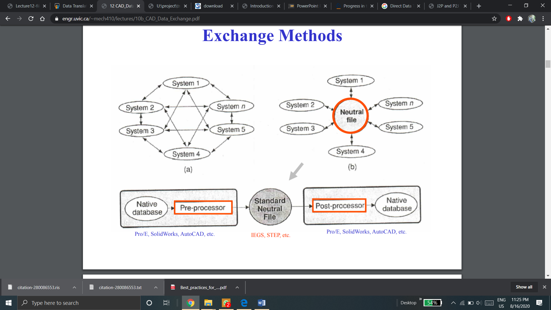
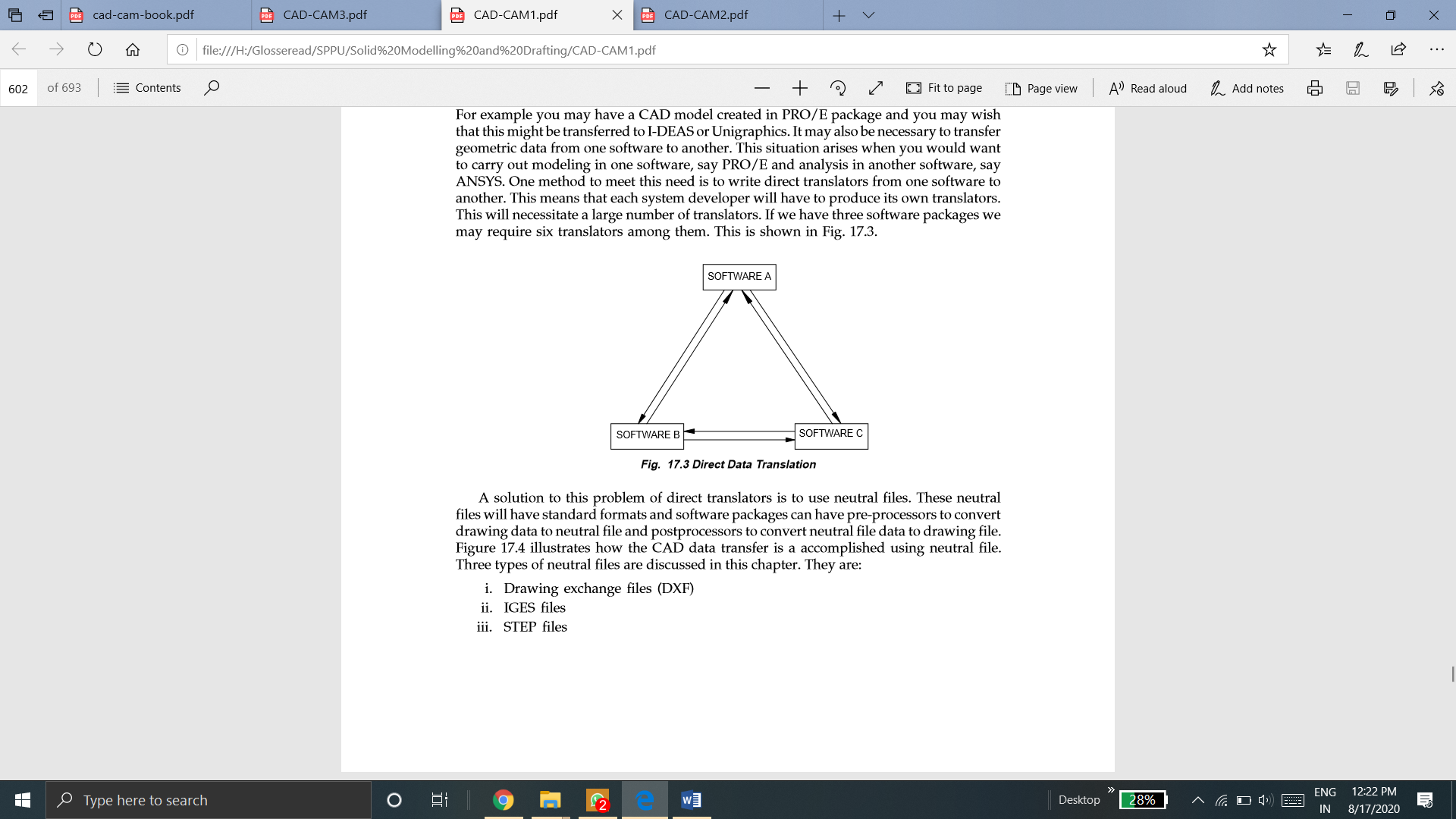
Direct data translators are the tools used in the CAD system to directly convert the CAD data from one CAD system to another. Due to direct Data translators, there is no need convert the CAD data into a standard file format. But all CAD systems do not support direct data translators. In direct data translation, once the CAD data is converted from one CAD system to another CAD system, it cannot be always converted back into its original format. Some of the CAD data may not be functional after the conversion, this shows partial functionality of Direct Data translators.
Requirement of translation of drawings generated in one drafting package to another often comes up. For example, you may have a CAD model created in PRO/E package and you may wish that this might be transferred to I-DEAS or Unigraphics. It can also be important to convert geometric infortion from one software to another. This situation arises when you would want to carry out modeling in one software, say PRO/E and analysis in another software, say ANSYS. One approach to meet this requirement is to write direct translators from one software to another. This means that every system developer needs to create its own translators. This will necessitate a huge number of translators. If we have three software packages we may require six translators among them. This is shown in Fig
The use of neutral files is a answer to the problem of direct translators. These neutral files consists of standard formats and software packages includes pre-processors in order to convert drawing information to neutral file and postprocessors to translate neutral file data into drawing file. Figure below explains how the CAD data conversion is achieved with use neutral file.
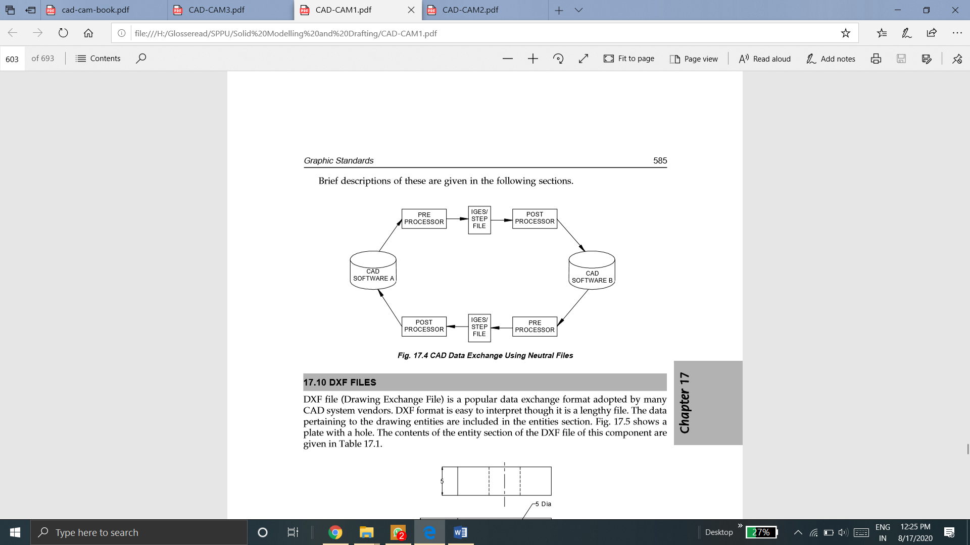
Neutral file exchange make use of an intermediary neutral format to convert information among CAD systems.
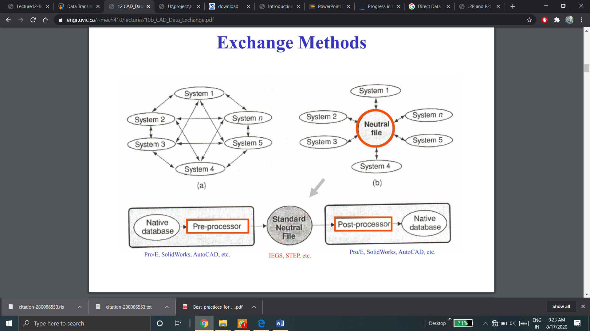
This method origins from a pre-processor that is embedded in the original CAD system that creates the neutral file from the original CAD file format.
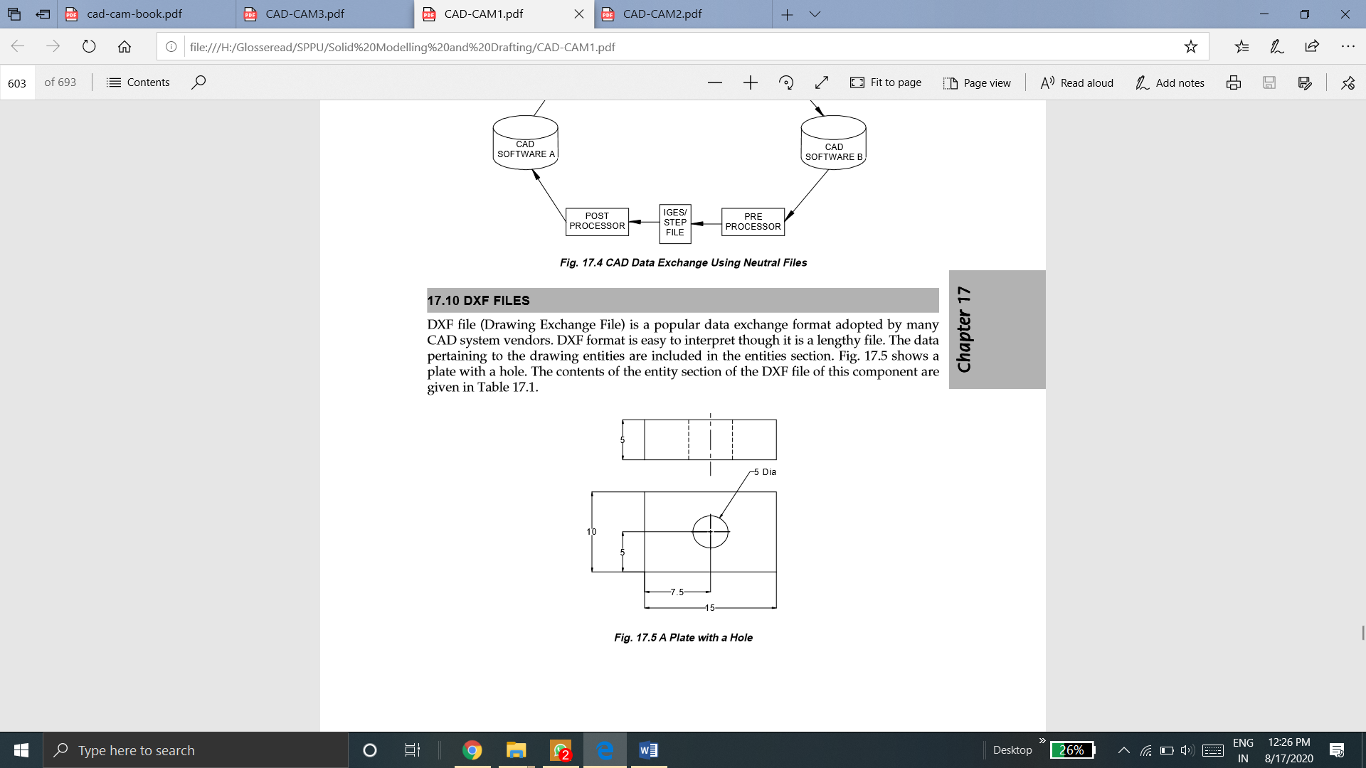
Various neutral CAD file formats are illustrated below:
Drawing Exchange Format DXF format has been developed and supported by Autodesk. It is for the use with the AutoCAD drawing files. DXF is not an industry standard developed by any standards organization. Rather due to large use of AutoCAD made DXF a default standard for use of a many of CAD/CAM vendors.
A DXF File is simply an ASCII text file extension of .dxf. It is specially formatted text. The full architecture of a DXF file is as follows:
HEADER Section
HEADER section contains general data about drawing like that in Global section of IGES. It includes the AutoCAD system variables database version number. Each parameter contains a variable name and associated value. This information is used for database conversion purpose.
CLASSES Section
This section of DXF file architecture holds the data for application-defined classes whose instances seems in the BLOCKS, ENTITIES and OBJECTS sections of the database. In the class hierarchy, class definition is fixed permenantly.
TABLES Section
This contains definitions for the following symbol tables which directly relates to the object types available in AutoCAD.
BLOCKS Section
This contains block (symbol) definition and drawing entities that make up each block reference in the drawing.
ENTITIES Section
This section contains the graphical objects in the drawing. It includes block references.
OBJECTS Section
This contains the non-graphical objects in the drawing. All the objects that are neither entities nor symbol table records are saved in this section. Examples of entries within the OBJECTS section are dictionaries that include multiple line styles as well as groups.
TERMINATE Section
It indicates the end of the file.
A DXF file is made of many groups. Each of the group occupies 2 lines in the DXF file. The first line is a group code. DXF file are either standard ASCII text or special binary form files which are more compact.
A DXF file created on the higher version of AutoCAD cannot be read on the other systems based on the lower version of DXF.
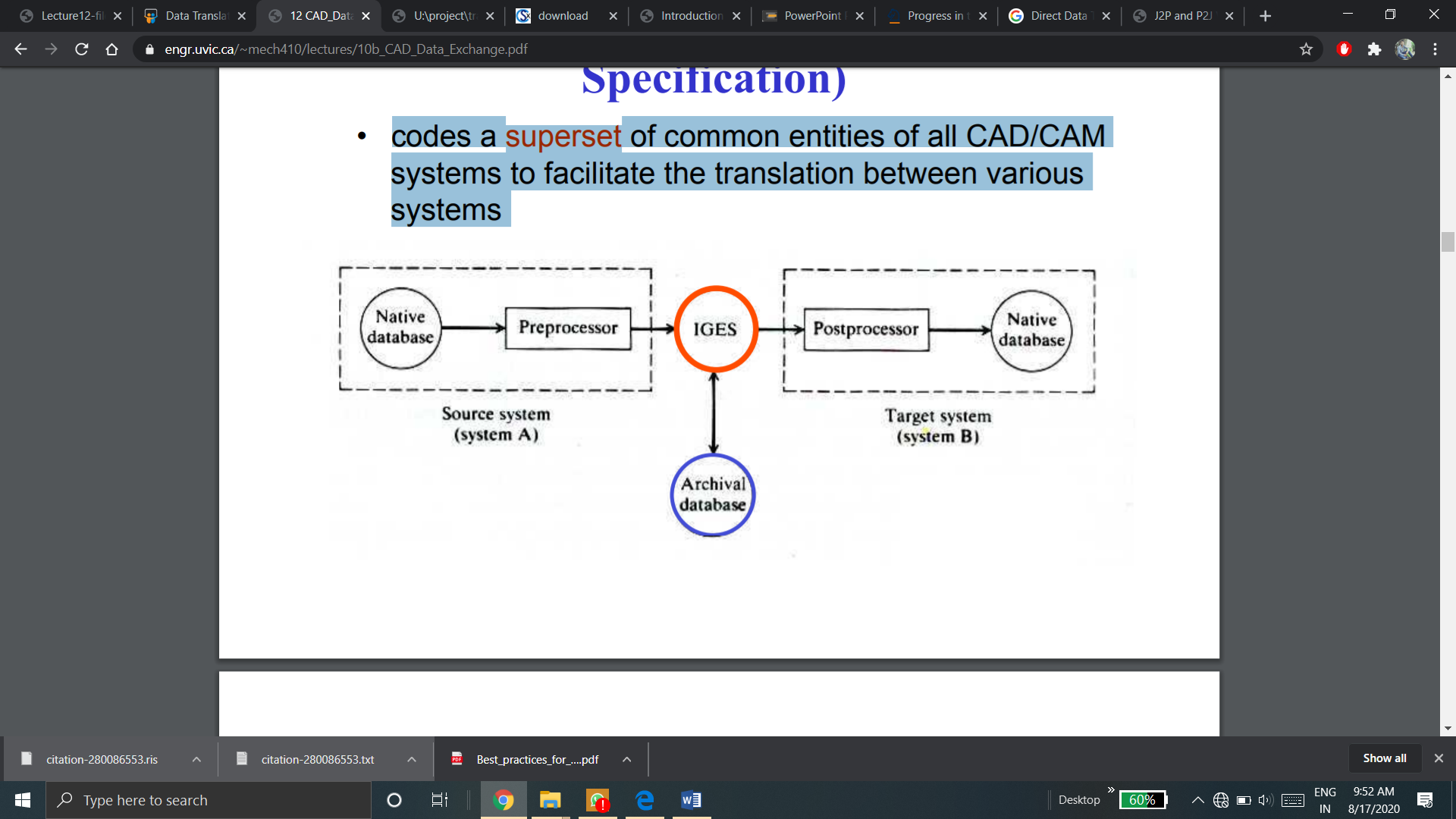
DXF file (Drawing Exchange File) is a popular data exchange format adopted by many CAD system vendors. DXF format is easy to interpret though it is a lengthy file. The data pertaining to the drawing entities are included in the entities section. Fig. shows a plate with a hole.
2. IGES
Initial Graphics Exchange Specifications (IGES) was first developed by National Institute of Standards and Technology (NIST) in 1980. Then it was adopted by the American National Standards Institute (ANSI) in the same year. It converts primarily shape (both geometric data and topological data) as well as non-shape data that is said as CAD-to-CAD exchange. It codes a superset of general entities of all CAD/CAM systems to facilitate the conversion among various systems.
Flag Section
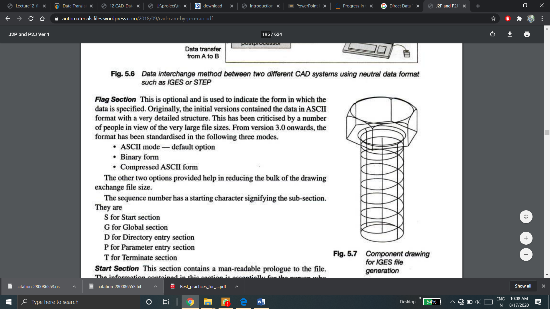
This is optional and is used to indicate the form in which the data is specified. Originally, the initial versions contained the data in ASCII format with a very detailed structure. This has been criticized by a number of people in view of the very large file sizes. From version 3.0 onwards, the format has been standardized in the following three modes.
The other two options offerd help in reducing the bulk of the drawing exchange file size.
The sequence number has a starting character signifying the sub-section.
They include
S means Start Section
G means Global section
D means Directory entry section
P means Parameter Entry section
T means Terminate section
Start Section
This section contains a man-readable prologue to the file. The information contained in this section is essentially for the person who would be postprocessing this for any other application. Any number of lines can be contained in this section.
A simple listing of IGES file for the drawing is shown in fig below
Global Section
This contains information about details of the product, the person originating the product, name of the company originating it, date, the details of the system which generated it, drafting standard used and some information required for its postprocessing on the host computer.
Directory Entry Section
For each entity present in the drawing is fixed in size and contains 20 fields of 8 characters each. The purpose of this section is to offer an index for the file and contain attribute information. Some of the attribute information such as colour, line type, transformation matrix, etc., may be present directly or through a pointer (to a record in the same file) where the necessary information is stored. It also contains the pointer to the parameter data section entry which actually contains the requisite parameter data.
Parameter Data Section
This data section is associated with the entities. For maximum convenience, a free format is given permission. It may contain any number of records.
Terminate Section
The terminate section includes a single record which specifies the number of records in each and every four preceding sections. It is for the checking purpose.
Limitation of IGES and DXF files
The IGES and DXF files were developed to exchange product data definition data instead of product data. Product data refers to the data related to the overall life cycle of the product.
Even though the specification of the IGES and the DXF file has been broadened to encompass some of these product data, the data carried by those files are inherently inefficient to be the product data supporting the entire life cycle.
3. PDES
PDES (product data exchange specification) is referred as the replacement to IGES. IGES organization developed PDES. PDES is aimed at defining a more conceptual model. Parts will be based on solids and defined in terms of features such as holes, flanges, or ribs. Instead of dimensions, for the parts that are to be manufactured, PDES should define a tolerance envelope. PDES also include non-geometric data like materials used, manufacturing process and suppliers. PDES could be a whole computer model of the part.
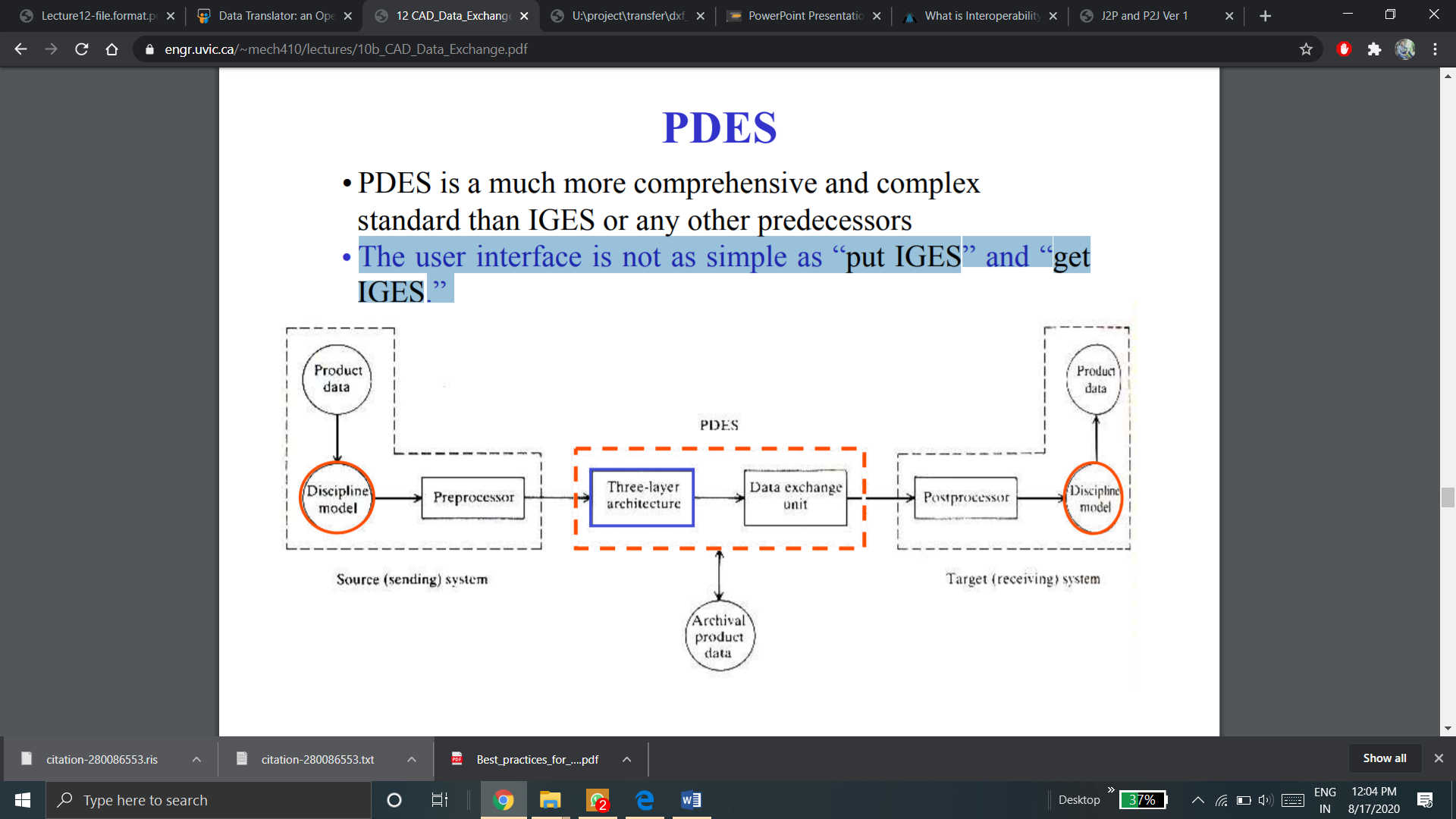
PDES is a much extra complete and complicated standard than IGES or some other predecessors
The user interface is not simple like the way to “put IGES” and “get IGES.”
PDES with use of STEP is the end result of an international attempt to develop a product design standard.
This format attempts to incorporate all aspects of product modeling including: geometry (B-Rep, CSG, Features), tolerances, electrical/electronics, function information, process plans, etc.
4. STEP
Seamless conversion of product data is essential to CAD/CAM/CAE systems. STEP stands for Standard for the Exchange of Product Data. It is the enabler for such seamless information transfer. It offers a global standard for storing, sharing as well as exchanging product information between various CAD systems. Although STEP itself is the basis for Product Data Management System (PDM). It consist of techniques of representing all important product specifications like materials, tolerances, shape information, finishes and product structure.
Whereas the Initial Graphics Exchange Specification (IGES) standard has widespread use, it has its shortcomings. It does not convey the extensive product information needed in the design and manufacturing cycle. Often IGES translators are required to move design data from one CAD system to another. STEP is often seen as a alternative for IGES. Though IGES can be in active use for few extra time within the future. Although the current focus of STEP is on mechanical parts, STEP is a data exchange standard that would apply to a wide range of product areas, including electronics, architectural, engineering and construction, apparel and shipbuilding.
STEP Architecture:
STEP architecture has four main components:
In a CAD modeling package, STEP data export has the below options:
(i) wire frame edges
(ii) Datum curves and points
(iii) shells
(iv) surfaces
(v) solids
The aim of this type standard is to allow the conversion of a computerized product model that too with all its supporting types of data in a neutral format.
5. ACIS
ACIS is another object oriented three-dimensional geometric modeling engine. It is designed for use as the geometry foundation in a 3D modeling application. ACIS is written in C++ and consists of a set of C++ classes and functions. A developer make use these classes and functions in order to produce an end user 3D application. ACIS complements existing applications by offering a unified environment for the modeling of curves, surfaces and solids. ACIS offers a foundation of common modeling functionality and flexibility to be adapted and extended for particular application requirements. ACIS integrates wire frame modeling, surface modeling and solid modeling by enabling these relacement representations to exist naturally in a unified data structure that is implemented in a hierarchy of C++ classes. ACIS bodies can have any of these forms or combinations of them. Linear and quadratic geometry is represented analytically and non-uniform rational B-Splines represent free-form geometry. ACIS is a boundary-representation (B-rep) modeler, which means that it defines the boundary between solid material and empty space.
ACIS ARCHITECTURE
The ACIS is designed by making use of software component technology. A software component is a functionally specialized unit of software. It is a collection of software packages (functions, classes, etc.) which are grouped together to serve some unique purpose. ACIS serves as a constituent part of a entire software system or product. A product is referred to one or more software components which are assembled collectively and sold as a package. Components can be arranged in various combinations to form various products.
Some of the ACIS components are:
Advanced Blending - Optional husk for blending beyond standard ACIS blending
AG spline - Spline library and interface
ACISMFC - Support for MFC based applications
Boolean - Unite, intersect and subtract operations
Clearance - Determine minimum distance between bodies or faces
Constructors - Basic topology construction; wire frame construction and editing; analysis (area, length, mass properties)
Cellular Topology - Divide lumps into sets of cells Euler
Operations - Expand, separate and combine lumps
Faceter - Generate faceted (polygonal) representation
Generic Attributes - Attributes that allow applications to exchange data
Graphic Interaction - Commonly needed graphic display functionality
Kernel - Basic entity and attribute support, topology and geometry entity classes; construction geometry classes
Local OPS - Optional husk for locally manipulating models
Meshing - Optional husk for representing a surface as a network of polygonal elements
Sweeping - Sweep a profile along a path
6. Parasolid
In most of the high-end CAD/CAM systems, the proprietary geometric modeler are embedded within the modeling application. Parasolid nothing but a is a portable kernel which can be used in multiple systems in both high-end as well as mid-range. In the early 1990s a number of software developers decided to adopt Parasolid. By adopting Parasolid, start-up software companies have eliminated a major barrier to application development - a high initial investment. This enabled them to effectively market softwares with strong solid modeling functionality at lower-cost. Today Parasolid is used as component software in many of the world’s leading CAD/ CAM systems. Unigraphics and Solid Edge, Parametric Technology, Solid Works Corporation ANSYS, Mechanical Dynamics, McNeal-Schwendler and Bentley systems are today using Parasolid. Companies such as Boeing, Israel Aircraft Industries and Mitsubishi Motors use Parasolid for internal development.
Parasolid’s modeling abilities contains:
In a nutshell, Parasolid incorporates object-oriented routines needed to create real life, complex models great accuracy, reliability and speed. Some of the functionalities in Parasolid are:
7. STL
There are many various ways to 3D print an object. But almost all of them use computer aided design (CAD) files for printing.
CAD files are usually a digitalized representation of an object. CAD files are used by engineers and producers to convert ideas into a computerized models which may be digitally tested, improved and also can be 3D printed.
CAD files must be translated into a language or file type in 3D printing or additive manufacturing. These file type are which a 3D printing machines can understand.
STL stands for Standard Tessellation Language. It is a file type or a language which is most commonly used for stereolithography and also in addition to additive manufacturing processes.
CAD models must be broken up into layers before they are printed in 3D, as additive manufacturing works by adding one layer of material on top of another.
STL files cuts CAD models giving the 3D printing machine, the information it requires to print each layer of an object separately.
A STL file is a format that is used by Stereolithography software to create data that is required to generate 3D models on Stereolithography machines. In fact, the extension .STL is known to be derived from the word "Stereolithography."
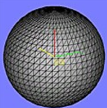
STL file is a triangular representation of a 3D object. The surface of an object is divided into a logical series of triangles. Each triangle is distinctly defined by its normal and 3 points representing its vertices.
The STL file is a full listing of the xyz coordinates of the vertices and normal for the triangles that describe the three dimensional object.
The aim to create a STL file is to achieve a balance among unmanageable file length and a well-defined model with clean curved geometries.
STL file has a translation issues.
The number of triangles that represent the model may be defined by the user in various CAD systems. If too many triangles are produced, the STL file length may be unmanageable.
If very less triangles are produced, curved areas are impossible to defined correctly and a cylinder may like a hexagon (refer example given below).
STL File Format
There are two formats of STL File:
Specialized software exists for specific fields, in the whole product manufacturing lifecycle, generating a requirement to ensure one has the right software which should be in the right place. It is without a doubt that many software solution offers have stood up to challenge this status quo, which has not been easy.
Hence, various software developers have developed the culture to complement others weaknesses and functionalities. Standardized neutral formats are used to universally bridge the gap between the different languages. ISO standards such as STEP and JT have came-up to a level where they are globally used by suppliers as an conversion format. As these answers give a good place to start, it is also necessary to know how the quality of the data or Product Data Quality (PDQ) is preserved and maintained in the overall process.
Quality of data refers to whether the modeled data meets a specific set of criteria that too in terms of 3D geometry data translation. It is necessary to satisfy the topological and tolerance needs of what one is converting to. This step becomes the basic step of having nice quality data.
In CAD data exchange, accuracy and consistency of the data plays an important role.
Accuracy: Accuracy of CAD data means how accurately the CAD data is converted from one CAD system to another.
Consistency: Consistency of a CAD data transfer means, same quality of data should be converted in every CAD data interoperability.
The requirements of the CAD file formats are different for different systems. These requirements for various system are discussed below:
Three-Dimensional Printing (3DP) a powder based rapid prototyping process. This technology was developed at the MIT and was licensed to many corporations.
The three main requirements of CAD file formats for 3D printing system or any other additive manufacturing based system like Fused Deposition modelling (FDM), Selective Laser Sintering (SLS), Stereolithography (SLA), Laminated object Manufacturing (LOM), etc. are:
Lot of people choose STL file format for 3D printing.
The most important consideration to consider here is the resolution of your model. If one tries to export an STL with a low resolution, the model will look faceted. Also your model will become very huge and difficult to share, if one exports an STL file with very high resolution. AMF(additive manufacturing file format) is the file format developed of additive manufacturing systems.
2. CAE
Computer-aided engineering (CAE) is nothing but the wide usage of computer software that aid in engineering analysis tasks.
Most of the CAE software do not support the files created in CAD software. It is needed to be converted.
The file format requirement for CAE software are IGES and STEP formats.
Those formats are great because they are supported by all CAE software as a way to exchange model information.
There are also proprietary CAD formats developed by software vendors to suit their own needs (Solidworks, Catia, Inventor, etc.). As proprietary CAD formats helps vendors to save data more specific to their software, hence proprietary CAD formats are useful for them. It is also a way to protect their technology.
3. FEA
Finite Element Analysis or FEA is the simulation of a physical phenomenon using a numerical mathematic technique referred to as the Finite Element Method, or FEM.
Like CAE, FEA systems also require and support STEP and IGES file formats of CAD data.
4. CFD
Computational fluid dynamics (CFD) is a department of fluid mechanics which makes use of numerical analysis and data structures to investigate and solve problems which consists of fluid flows.
Following standard file formats are supported by CFD systems
Along with these standard file formats, some of the CFD systems also support some proprietary file formats developed form some CAD software vendors. Few examples of such file formats are:
5. CAM (subtractive manufacturing)
Computer Aided Manufacturing (CAM) is referred as the use of software and computer-controlled machinery that helps to automate a manufacturing process.
NC, CNC machine tools are examples of subtractive manufacturing in CAM
In order to manufacture a component directly form CAD data, the most commonly required CAD file format is DXF/DWG file format.
Other file formats that supported are: IGES, STEP, etc.
6. Multi Body Dynamics (Motion Simulations)
A multibody dynamic (MBD) system is one that contains a solid bodies, or links, which are linked to each other by joints that limit their relative motion.
Multi body dynamic system requires the translation of CAD data.
Mechanical models are usually stored in the DWG format. The geometry of each part is exported to the STL file format.
There is some CAD software like Solidworks which has its own motion simulation. The CAD data file from Solidworks can directly be used for multi body dynamics.
7. Computer Aided Inspection (CAI)
Computer-aided inspection (CAI) is nothing but the use of computer-based software tools that helps quality engineers, machinists and inspectors in producing product components. Its basic goal is to generate a speeded production process and components with more accurate dimensions and material consistency.
Various CAI system does not require CAD data interoperability. Various neutral CAD files supported by CAI systems are STEP, IGES, ACIS, DWG, etc.
8. Computer Aided Technologies (CAx)
Computer-aided technologies (CAx) is the use of computer technology to aid in the design, analysis, and manufacture of products.
The most known standards used in the product data exchange between computer-aided technologies systems are
9. AR/VR applications
AR may be referred to as a system that fulfills three primary features, which is a combination of real and virtual worlds, real-time interaction, and accurate 3D registration of virtual and real objects.
Virtual reality applications are applications which uses virtual reality (VR), an immersive sensory experience that digitally simulates a virtual environment.
AR/VR Application based systems requires VRML file format. In order to achieve this file format, CAD file is directly converted into VRML language-based data file if the kinematics and animations are missing in CAD data.
In order to present the desired animations in VR, additional DCC programs must therefore be installed. The position and orientation of each individual part for each stage of animation must therefore be saved in VRML file
Meshing packages have the problem of dealing with a host of geometry problems. Many of these problems can be categorized as file conversion issues. Basically, the geometry that is used in a meshing package isn’t been generated there while in one of various CAD packages. Misrepresentations in the geometry can be introduced by exporting these type of files out of CAD as well as into a neutral file format (example are IGES, STEP, SAT) which are accepted by the meshing software. A second translation can be important if the CAD and meshing packages don’t support the same file formats. It can possibly introduce even more bigger problems.
Another worry that is caused by file translation is due to tolerances.. If the tolerance of meshing software is finer as compared to the tolerance of CAD package, this disparity in tolerance can purpose next geometry modification operations in the meshing package deal to inadvertently generate sliver features that tends not to be easy as well as tedious to deal with. This tolerance trouble additionally causes misalignment problems between among volumes of assemblies, hindering the sharing of coincident geometry to create a conformal mesh.
Several approaches for addressing the geometry cleanup issue typically offer operations which are automatically applied to the geometry. Very powerful way in lots of cases, they commonly lack the potential for the user to have control over the resolution of these CAD problems by still maintaining the option towards automation. The ITEM environment offers tools to both diagnose these common issues and to offer a list of solutions from which the user may select that will correct the problems.
Features in a solid model which must be carefully considered and addressed before meshing, for the purposes of mesh generation, commonly fit in one of the four categories given below:
Having ability to recognize when a problem exists also what operations are needed to apply to resolve problems in each of the four types described above, is certainly an art-form and needs significant experience to grow to be proficient. ITEM is intended to give the user assistance along in the manner by detecting potential issues and suggesting answer they might consider. Hence, ITEM wont take the place of an skilled user.