Unit 6
CAD customization and Automation
Traditional way of design was designing or drawing on sheets. 2D drawing was required. But now-a-days 3D drawing model has gained more importance in market. This is because of the limitations of 2D drawing. There are various methods of manufacturing which require a CAD fie for manufacturing like 3D printing, CNC, etc. In order to create 3D model easily and rapidly, CAD system need to be customized. CAD customization had also gained importance in today’s market. CAD customization has been made easy due to APIs. Along with customization, Product and Manufacturing Information PMI is also important. PMI helps user to give or edit dimensions to a 3D model. Model Based Definition has helped reduce the cycle time from receipt of a design to the shipment of product.
The various limitations of 2D drawing are illustrated below:
2D drawings are unable to capture the complications of product design. Assembly and fit is not considered by 2D drawings. Products which are produced from a 2D sketch need a lot of work because there may be lots of errors. If products are produced by lots of people, the checking process gets more and more complicated. The drawings are pressured to go backward and forward again and again until lastly, after exhausting hours, the process is completed.
3D models give a lot of data regarding fit and potential problems. Because 2D drawings are unable to display that information, adequately, they are pressured into physical prototyping. In the case of a 2D drawing, the only manner that can stop issues is to create the prototype, tear it down, and rebuild it again. This prolongs the product development cycle dramatically as you’re pressured to involve reworks and re-engineering of prototypes.
Making changes in designs is a time-consuming process, and it’s even more tedious for 2D designs. Designs may need to be regenerated many times in various views to capture all the details of one part. When changes are happening, they need to be reflected in all of the drawing views, needing the designer to regenerate many drawings. This is completely non-sense when 3D CAD models are fast to make an easy to edit and multi functional file.
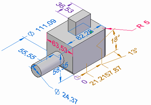
Product manufacturing information (PMI) is essential engineering or manufacturing information embedded within a 3D CAD file. It is governed by ASME and ISO industry standards.
PMI may include the following information:
3D PMI is a big step to digital transformation as well as quality control for any company or department.
Once design engineers finish their 3D CAD design, they spend extra time to generate 2D drawings from their 3D design to pass-on product & process information like GD&T.
Then manufacturing as well as quality control engineers depend on those 2D drawings to MANUALLY input GD&T and other information into their CMM (coordinate-measuring machine) or CAM (computer-aided manufacturing) software. It may be occasionally interpreting ambiguous data from 2D designs.
Translating and depending on 2D drawings are useless when important & correct information can be added within the 3D CAD. This gives more time & resources for design as well as manufacturing and greatly reduces the ability for mistake or error.
Basically, this becomes a first point to connect departments and companies into digital transformation & automation.
PMI can be divided into two types of levels.
Product and Manufacturing Information (PMI) contains non-geometric information which is fixed directly to a 3D CAD model to refer engineering and manufacturing specifications, dimensions, and text along with geometric dimensioning and tolerancing (GD&T). PMI is piece of Model Based Definition (MBD). Also together PMI and MBD elements are a part of a Digital Twin.
Application of PMI to a 3D model can minimize or eliminate the usage of 2D drawings and may be used downstream to perform tolerance analytics and inspection of coordinate-measuring machine (CMM).
PMI is a type of command in NX which provides the ability to generate or attach dimensions and annotations to create the 3D model. Along with this it needs model views to be similar to the views on a drawing. These dimensions and annotations are associative to the three-dimensional geometry. If it is determined that a 2D drawing is needed then the PMI may be inherited from the 3D model and automatically carried out to the drawing views.
Product Manufacturing Information also called as PMI includes dimensions and annotations which are added to the 3D model as well as which can be used in the processes like review, manufacturing, and inspection.
PMI dimensions also offer an necessary design modification tool in synchronous and ordered modeling. By changing dimension values, one can edit the model. One can lock and unlock dimensions in order to control the way that connected model faces respond to dimension value edits. Additionally, one can control the direction where the dimension edits are applied. This simplifies the design, testing as well as update process.
The Solid Edge PMI application attaches the functionality of adding dimensions and annotations which generates wholly rendered 3D model views along with 3D section views, drawing formatting, and publishing the data.
Model-based definition (MBD), sometimes called digital product definition (DPD), is the practice of using 3D models (like solid models along with 3D PMI and associated metadata) in 3D CAD software to offer specifications for single components and product assemblies. Geometric dimensioning and tolerancing (GD&T), component level materials, assembly level bill of materials, engineering configurations, design intent, etc. are the types of data which is included. Other approaches have historically needed accompanying usage of 2D engineering drawing to give such information.
MBD is the process consisting of only ONE reference source which is a 3D CAD model with semantic PMI or three dimensional annotations must be the definitive authority model downstream.
It is a unifying factor for design, manufacturing, quality along with other disciplines to move far from conventional drawing-based workflows to CAD model-based totally with all production definition and geometry contained in one digital place
MBD is the practice of putting either conventional or GD&T dimensions to the 3D model itself t the time of the design process. The engineer or designer can put these dimensions on the model for different uses.
Traditionally, designers used to develop in 3D CAD using tools like NX, CATIA, Creo, Solidworks, and others, however, their product and process information is then projected down into 2D drawings--some on literal paper--which is not machine readable.
Thus, the manufacturing or quality control engineer needs to MANUALLY enter the GD&T and other vital information.
There is no need to project the data into 2D drawings with the use of MBD. The CAD file can be directly converted to systems for manufacturing, inspection, etc. This is because of MBD.
MBD guarantees for minimum errors or mistakes, maximum time saved along with company-encoded knowledge that is to be performed quicker with quality repeatability.
MBD in Data and Analytics
Examples of Data and Analytics are Industry 4.0, advanced manufacturing, digital twin, digital thread and model-based enterprise. These terms and MBD make use of good quality data to solve business issuer or maximize improvement of business products.
Unfortunately, that data, for many manufacturers, is not been used.
Quality and inspection departments conduct the validation of products that comes out of the shop floor or measuring parts and also that comes with pass or fail decisions. But, that data is not usually reintroduced and returned to ecosystem and usually discarded regardless of being highly valuable.
MBD makes sure to have data that is tied to the model for improved designs, improved parts, improved operations along with improved business decisions.
MBD in Inspection
NOW-a-days, MBD plays an important role in the inspection of the product.
After the identification of measurement tasks aka Bill of Characteristics, information is stored in MBD model to generate FAI (first article inspection) or PPAP (production part approval process) documents. Using PMI, the model is given 3D dimensioning. Measurement plan is assigned to generate inspection program for CMM. After gathering results, statistical analysis is carried out. Final step is to tie back to MBD model for single source of truth.
MBD in Additive manufacturing
AM offers the ability to create complex designs never before imagined. Many of these designs are too complex to document in a conventional 2D drawing File. These new can designs be correctly documented only with the help of MBD.
The most important application of PMI is 3D viewing. With the use of PMI, it is possible to view the CAD model in 3D along with the dimensions and tolerances. One can edit the dimensions and change the 3D model according to the requirement.
PMIs in 3D viewing can be a device that assists the user of this analysis to have directly the PMIs data in 3D models in prior phases. In future, imagination of a tool is possible that enables to perform the tolerance analysis directly from a three dimensional model in DMU with PMIs.
PMI in NC-Simulation
During the use of NC-Simulation, one critical point is programming. The software of NC has to detect all the PMIs and Features in order to create the sequences of manufacturing. The main technique concerning the conversion of data for the programming in NC is classified in 3 phases: the first phase is the implementation in the model CAD of the information important for the finish (Features). Then an interface insures their transmission to a programming NC tool. In this last phase, the sequences of manufacturing importance, the tools and various technological factors for manufacturing are selected according to the converted data. 3D viewing with PMIs can be a solution for the interface among CAD systems and NC programming. During the creation of NC programs, PMI in 3D model can be used efficiently. These programs are used in NC simulation.
PMI in Finite element analysis
For finite element analysis, the user has to access several information concerning the product to be simulated. The main PMIs used for the simulation are functional dimensions with minimum and maximum tolerances: simulations can be made for each limit. Moreover, for sensitivity studies during the simulation (critical parameter, etc.), the user varies the value of a dimension between the upper and the lower value of its tolerance. The other PMIs as roughness are used for particular cases. PMIs will be a tool that helps the user to take the information he needs for the modelization of the product used for the simulation. PMI may be used directly by the user in 3D model for generating the simulation model as well as for leading sensitive studies.
PMI in Tolerance analysis
The tolerance analysis is a fundamental point for design engineers in performing tolerance studies and optimizing tolerance budgets. Few tools already exist and use generally 5 steps which are given below:
• Generation of the design
• Definition of functional parameters for every component
• Verification of the functional parameters for every element
• Generation of the functional assembly model
• Performance of the functional parameters analysis of the assembly
Functional features are defined and related to one another according to the Geometric Dimensioning and Tolerancing (GD&T) Datum references and feature control constraints (i.e. form, orientation, location...). PMIs are also fundamental because they are the basis of all this study.
In engineering departments, R&D centers & Design departments we use CAD to reduce the product development cycle time. CAD helps us to achieve this with maximum efficiency. CAD software gives us speed, efficiency & accuracy. If you still believe that your cad solution can be better and more automated, please contact us and let us help you achieve this. All you need to do is to make a list of your requirements and how you want to automate the your workflow.
Customization of CAD software assists customers to do things quickly, efficiently and perfectly. Most leading CAD software like CATIA, Solid Edge, SolidWorks, CAD software, Inventor, etc. enables users to customize by making use of their own respective API package. CAD customization may be a little macro to a whole workbench within the software. Organizations incline in the direction of customization for KBE, design and process automation or for the integration with the other tools.
CAD Customization is referred as the process used to automate the repetitive task included in design and drafting or modification of the general utility into a specialized, tailor-made application of Industrial & commercial products. The inputs may be like the type of Software Requirement Sheet or may be a CAD file with different details. The deliverables may be in the shape of executable, GUI files, Database files as well as Documentation.
Customization of CAD products was been able to be done from the beginning. CAD customization challenges the popular “One Size Fits All” tagline. Industry specific CAD products can be developed due to CAD customization. Overhead cost to the company was added due to maintenance of multiple CAD products. Many companies that develop these type of products know that they are unable to offer specialized features for every industry and every type of user. These companies offers API, Documentation and developer tools that may be used in order to customize the product.
CAD customization can be used for the following:
Steps for CAD customization
Before developing customized CAD software, make some preparations as follows:
Method for customizing CAD software
Most CAD systems provide the following two mechanisms
Visual Basic Applications or simply VBA is an event driven programming language developed by Microsoft. It also enables integration with various applications which make use of VBA. The implementation of VBA in CAD customization is simple to study and use. Developers can generate application prototypes as well as receive feedback on designs in a faster way. VBA offers an exceedingly efficient path for manipulating CAD objects and also exchanging data with different applications.
Another approach for customizing CAD software is by developing add-ons by making use of open source API’s and toolkits. One is able to develop API implementations by making use of a developer toolkit. In recent days, most of the API’s evolve as open source that makes the complete operation a smoother. API’s may be fabricated as per the necessities and may be applied as an extra feature. One crucial factor is that the API should be compatible with the CAD software being used.
Advantages of CAD customization
Customization of CAD software has indeed introduced us to many benefits which are as follows:
Disadvantages of CAD customization
The main application of customization Interface are as below:
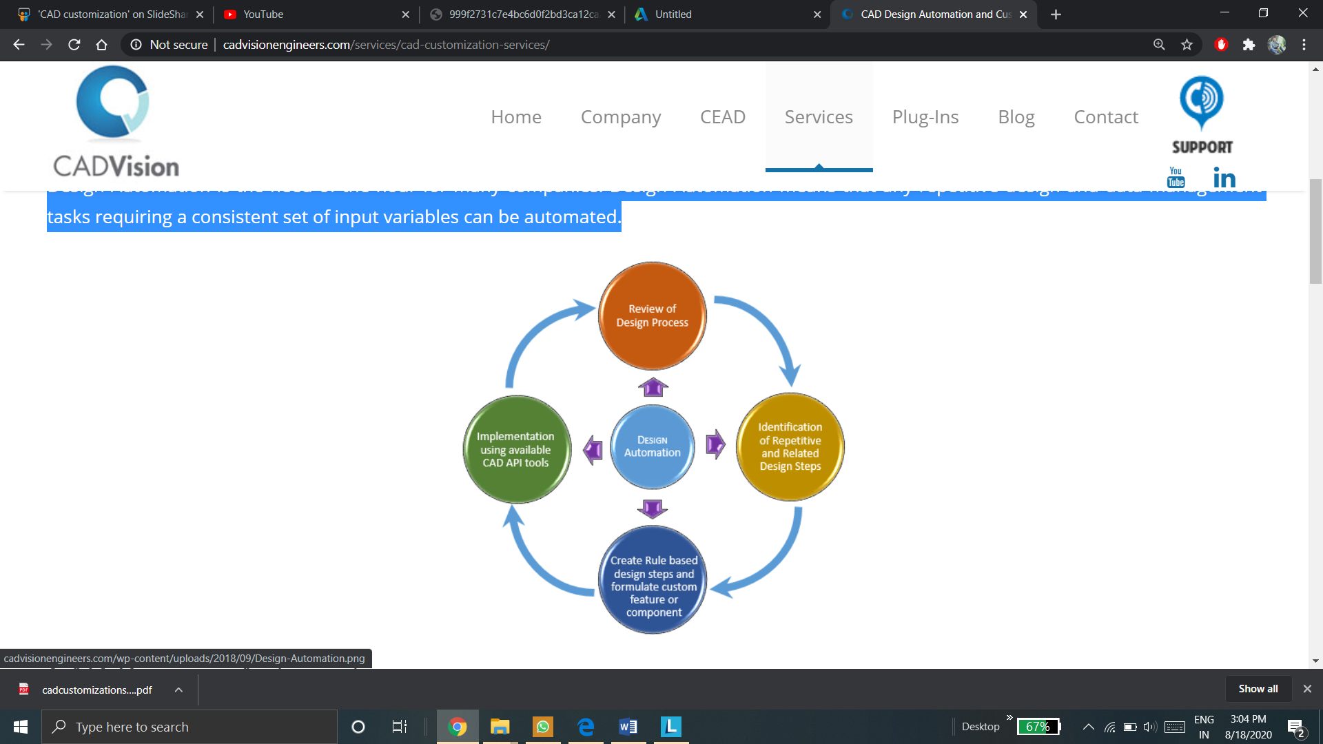
Various advantages are obtained when CAD customization with design automation are integrated in engineering application. The production of a drawing and design of a mechanical component may be created, with great precision, with CAD customization. This enables engineers to make fast modifications to all of the issues observed in the design. In simple words, the design may be customized in accordance with the requirements outlined prior or later the CAD design is created. Also, mechanical customization and manufacturing automation pass hand in hand in connection with CAD software application.
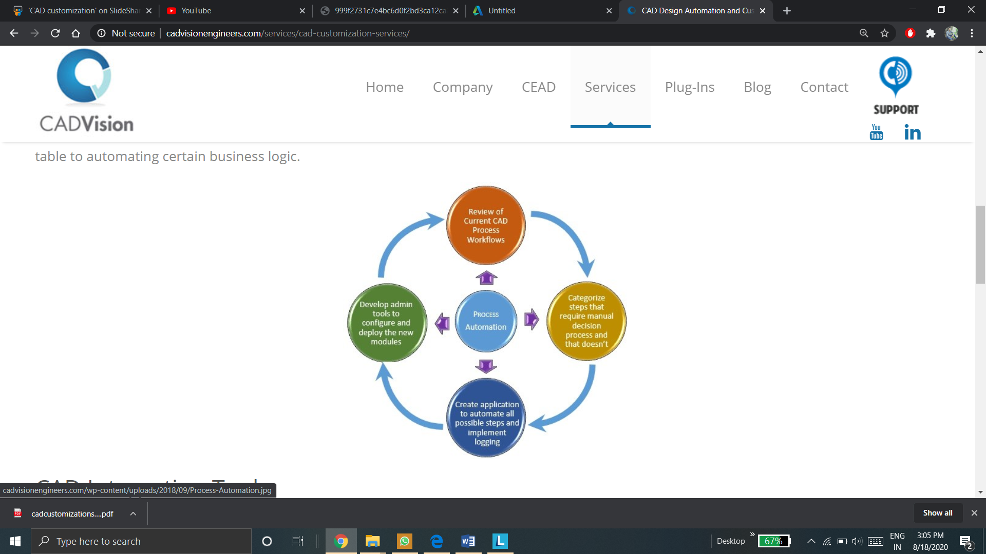
In the industry, the need of Process Automation is same as that of Design Automation. Engineers can focus on the high stage design, by permitting the customization for process automation to attend to of little things. The little things can range from including a revision automatically in drawing table to automating specific business logic.
Drafting packages provide extensive customizable features. Many packages are provided with LISP based or “C” based programming environment. These can be used to develop utilities which can be put in menus and these will behave like any other command in the software. Apart from developing these programs customization involves many other tasks which are listed below:
More applications of Customization are:
Product Customization or Product Personalization is referred as a process of delivering customized goods along with services to the customers as per their requirements and needs. Customers can either approach as a merchant to make some of customizations in a product or he may personalize the products by self in the same way they want.
In product customization, user can customize the commands, size of icons, colour of environment as required or feasible to the user.
Various product customization approaches are as follow:
Customization of the commands require for the part model creation in CAD modeling of the CAD software UI is the part modeling customization approach.
In most of the CAD software’s user interface, all the commands are in the command manager at the top of the UI of that CAD software. One can change the place of the command manager in the way they want.
User can add the commands he wants to design a product model and can hide other commands he don’t want for the design of the product. Or he can hide those commands he rarely use.
For example, to construct the product part model, user don’t require Data migration tool or MBD tool, he can hide that tool. And user will require the sketch tool and feature tool to model the part. He will place those commands in the way he want, such that he can have easy access to it.
Generally, many CAD software provide tool for customization. It can be accessed by right click on the command manager or header bar of the software’s UI. Access to customization may vary from UI to UI for different CAD softwares.
If the customer requires only some specific commands for the part modeling, he can contact vendor and customize the CAD system in the way he wants.
For example, If the customer only needs to design the parts of uniform cross-section. He may ask the vendor to hide commands like Loft, Sweep, etc. and place the commands like extrude, revolve such that he may have easy access to it.
If the customer needs to check the mass properties of the part models, he may customize the CAD system such that, Evaluate command tool will be placed on first screen where, generally sketch command is present in most of the CAD systems.
Suppose user have to create the part model require for sheet metal working, he may customize the CAD systems UI such that he can access the commands require for sheet metal working easily.
Along with commands user can change the icon size or color of the part modeling environment.
User have the option, in many CAD systems, to add the shortcut tool. In part modeling customization approach, user can customize the shortcut tool by adding or removing the commands like extrude, revolve, sweep, fillet, chamfer, mirror, circular pattern, linear pattern, measure, etc. in the shortcut menu.
Along with shortcut bar, one can add commands in the mouse gesture menu. The commonly used part modeling commands can be added to this feature of customization. One can add 4, 6, 8 or 12 commands or buttons in mouse gesture for part modeling customization.
2. Assembly Modeling Customization
Just like part modeling customization, user can customize the commands require for assembly of the parts created in part modeling.
Customization of the commands required for assembly modeling is the assembly modeling customization approach of product customization.
Commands like insert component, insert sub-assembly, mate features can be customized.
For example, if the coincident mate is required by the designer to assemble a product, he may place coincident mate feature in the command bar as a separate command, instead of traditional approach of giving coincident mate command.
Another way is to add the coincident mate command in the shortcut menu. User can also customize the shortcut menu in the assembly modeling customization approach just like the way in the part modeling customization approach.
With the help of script, user can automate any command like in above example, user can automate coincident mate command for every part inserted by just selecting or clicking on the face to be made coincident.
If the customer is interested in only simulation of the assembly, he can hide the commands like insert part and mate and place commands require for simulation on the first screen.
User can change the size of icons, location of icons of assembly commands, color of background of assembly environment in the assembly modeling customization approach.
Just like in part modeling customization, along with shortcut bar, one can add commands in the mouse gesture menu. The commonly used assembly modeling commands can be added to this feature of customization. One can add 4, 6, 8 or 12 commands or buttons in mouse gesture for assembly modeling customization.
In mouse gesture, one can add shortcut toolbar, normal to feature, escape button, etc.
3. Drawing sheets and PMI customization
Many times, a 2D drawing is required or is sufficient instead of a 3D model.
Just like in part modeling and assembly modeling customization, drawing sheets can also be customized.
User is able to change the size of the drawing sheet as per the size of drawing and can choose suitable scale for the drawing. User has choice to select the measurement system. User is able to change annotations in the drawing sheets.
User can change the size of the title box on the drawing sheet in drawing sheet customization. User can create its own template of drawing sheet and save it for further use, so that he doesn’t need to set the template every time.
Along with drawing sheets, user is able to customize the PMI. If user wish to realign the dimensions to the product, he can do it the way he wants.
If user is designing products with same materials, using scripting, user can automate the material selection in PMI customization.
CAD automation allows users to automate translation and repair processes while not having to open or view the documents graphically. Hundreds and thousands of files can be processed automatically at one time.
CAD design automation automates the process of generating a technical drawing or model efficiently Design automation enables designers and engineers to speed the development of design variants and automate repetitive design tasks, which accelerates the design process, saves time and development costs, and increases productivity.
Automation in CAD has simplified tasks that could have been very tedious and time-investing to do manually. At the same time, it has generated a little black-box of thriller of ways of how the tasks in the software are actually performed.
Steps of CAD Automation
There are three main steps in CAD automation
Step1: Setup
Manufacturer uploads their CAD files to create the 3D visuals and engineering regulations for configuration by the last buyer.
Step 2: Configure
The product is configured by the customers based on their requirements. The user is avoided from configuring some thing that is not permitted in manufacturing.
Step 3: Generate
Generate cut-sheets and manufacturing-stage drawings for the shop floor and pass information directly into PLM, PDM and also various downstream business systems.
Benefits of CAD automation
CAD automation helps automate the quotation process, saving huge amounts of time for anyone contributing input in the product life cycle.
Sales teams dont have to wait, with CAD automation, for engineering to validate configurations or manually process drawings.
Because design constraints are already defined and validated in configurator, one can feel confident about the integrity of the design when it is generated automatically.
The high number of the files and complexity of models make the task time-consuming and tedious many times. For example, even opening and closing each CAD file takes a lot of time. When hundreds of CAD models need to open and verified, it takes more than one hour to finish the task. The work is to complete this task and make it easier with the help of Commercial CAD software’s API (Application Programming Interface), that may be used to automate and customize the CAD software. The API contains hundreds of functions that you can call from Visual Basic for Applications (VBA), VB.NET, Visual C#, Visual C++ 6.0, and Visual C++/CLI. These functions provide direct access to CAD functionality such as opening a file, check the important physical properties of three-dimensional models. Custom API program has been programmed for the task. The custom program performs the internal commands in CAD software and retrieve the information that one requires from each CAD file automatically. The program opens the multiple CAD files in the folder and check each file’s physical properties and save the information in MS Excel for the review. The program checks the volume (w.r.t the given coordinates) in two standard units (English and S.I. Units), the creator of model (to prevent the plagiarism) and degrees of sketch.
An application programming interface (API) is a computing interface that defines interactions between multiple software intermediaries.
An Application Programming Interface (API) is defined as a set of commands and functions as well as protocols that programmers uses at the time of building a software.
It enables the programmers to make use of predefined functions instead of writing them from scratch, in order to interact with systems.
Characteristics of good API
API Key
An application programming interface key or simply called as API key is a code passed in by computer programs saying an API in order to identify the calling program, its user or its developer to the Web site. API keys are used for tracking and controlling the way that the API is being used. API key is also used to protect malicious use or abuse of the API.
Uses of API
There are different types of APIs
Web APIs are APIs that can be accessed using the HTTP protocol. This type of API refers endpoints and legitimate request and response formats. Web APIs include the APIs used to communicate with the browse
2. Open API
Open APIs are called as external or public APIs. These are available to developers with other users with minimum restrictions. They might need registration, and access of an API key, or may be wholly open. They are intended for external users (developers at other companies, for example) to access data or services
3. Internal API
Internal APIs are designed in such a way that they are hidden from exterior users. In a company, internal API is to share resources. They allow different teams or sections of a business to consume each other’s tools, data and programs.
4. Partner API
Partner APIs are analogous to open APIs, but this type of API feature limited access, usually controlled by a third-party API gateway. They are often intended for a certain purpose, including offer to access to a paid-for service. This is a very common pattern in software as a service ecosystem.
5. Composite API
Composite APIs enables developers to access many endpoints in one attempt. These can be not similar endpoints of a single API, or they can be multiple services or data sources. Composite APIs are helpful in microservice architectures, where a user might require data from many services to perform one task. With use of composite APIs may minimize server load and improve application performance, as one call can return all the information a user that he requires.
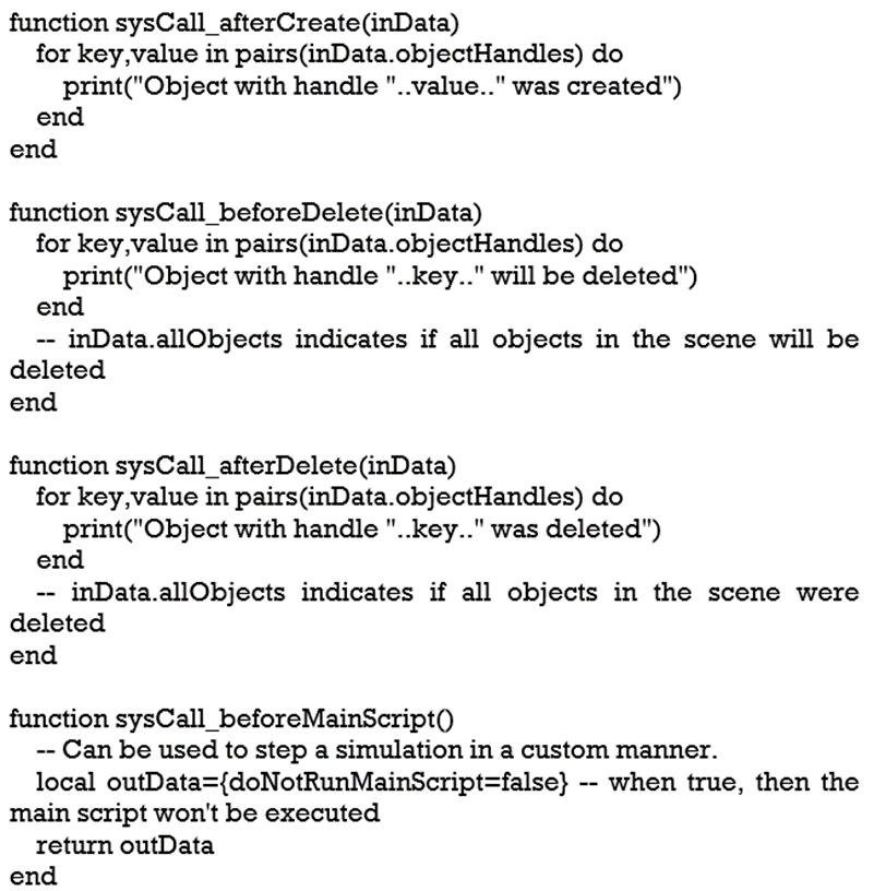
The following system object map shows how the objects in your system are related. The solid black arrows refers needed relationships, and the dotted arrows refers optional relationships.
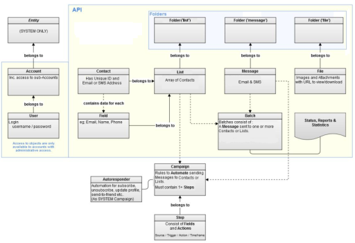
The box labelled API contains the objects that many Users having API access can process. Accounts and Users shows up in an adjacent box as they are accessible from the API, however only to Users with Administrative access.
The API are located outside the API along with their steps and Autoresponders as they are unable process Campaigns. API techniques may act on Autoresponders, but cannot act in relationship to Campaigns. Autoresponders must belong to a List and contain a message.
Almost every feature that is available in a CAD system can be automated. Thus, the use of the API is needed at the time of development of engineering applications. These applications can resource the productiveness of many workshops that produce a limited range of products or that are specialized in a specific range of mechanical systems (i.e. machinery). The general advantages in the design process of the use of the API are easily seen. At the start, the development time of a product reduces drastically. Also, the applications which may be generated with the use of the API may combine different functionalities of a general purposes CAD system in a sole way and also must be easy to use interface. Along with this, the corelation between various software is applicable, that supplements the capability of an all-around software tool.
It is able to develop a collection of CAD based applications with the using the automatic programming interface API of a general purposes CAD system. These applications can be easily accessed with the assistance of a simple user interface. The provided applications were developed with the help of the VBA (Visual Basic for Applications) programming language which is embedded in the certain CAD system. One such application may be used to create the solid models of the pneumatic cylinder’s components complying with the ISO standard 15552:2004. Then the created models are attached to form the assembly of the pneumatic cylinder. Also, with the full assembly model, extra functions become available.
Customization scripts usually are embedded scripts that are used to customize a CAD product or simulation scene. They are attached to scene object, and they can be easily recognized from their dark script icon in the scene hierarchy.
The main properties of customization script are given below:
Above given properties enables customization scripts to share few of the good features of add-ons and also that of child scripts. Customization scripts enable the generation of customizable models for instance. One could imagine a model which was dropped into a scene and is able to configure or adapt itself even when simulation isn’t working. This can be a robot where the user is able to adjust the different link lengths with a single slider repositioning.
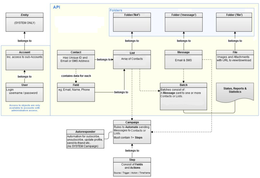
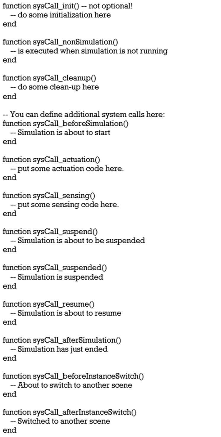
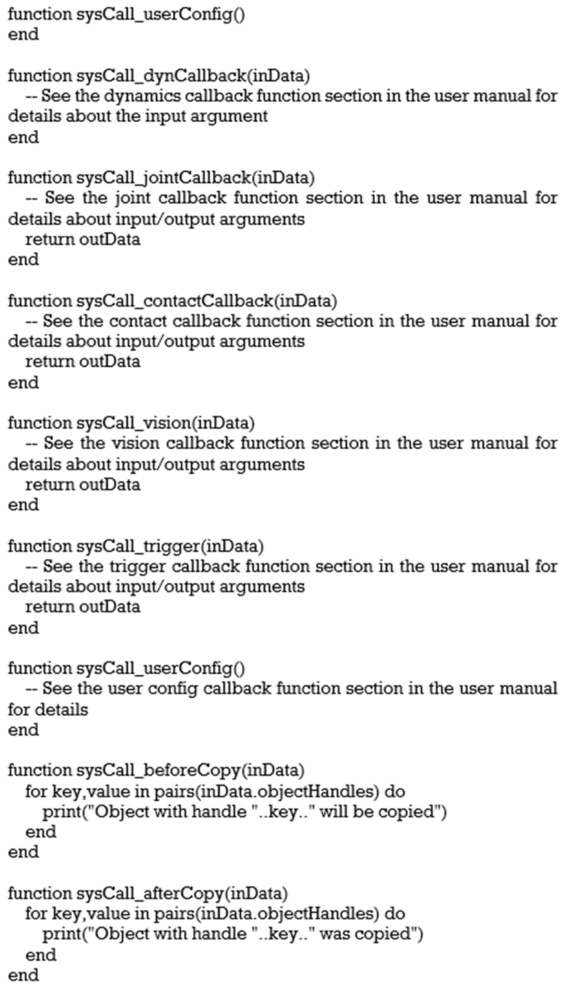
Customization scripts must include a collection of system callback functions. These scripts should perform some task and then return control, every time they are called. Customization script functions are called by the system very often, but also by the main script, by following a precision execution order. Callback functions are also supported by customization scripts.
VB.net is the language that is generally used for the scripting for customization.
A customization script is segmented in several system callback functions, as skeleton of script is shown below:
If there is no control over the CAD file management, it can result to conditions where files may be lost or overwritten. Poor management can also result in re-duplication of files and the wrong CAD files are revised.
To avoid these problems, below are 5 CAD file management techniques:
To start with, ensure that one have a logical folder system for all of the CAD files, irrespective of they’re a DXF or DWG file format. Sort them out by project name and make sub-folders within each and every project folder. For example, Project – Concept -- Design -- Completed.
Standardizing this system will help you to structure your projects in a simple, logical manner, meaning you can locate your CAD files quickly and efficiently.
2. Naming Conventions
Creation of a standard naming convention is also a best manner of maximizing efficiency. It might sound very primary, but it has ability protect a lot of confusion while trying to figure out at what location a certain file is as one is unable remember the name.
One of the most common naming conventions differentiates among files making use of number sequences and dates. For example, your file can be named ‘file-name_xx_2020’. This can help to remember and stay away from confusion while locating files on the system.
It should be noted that conventions only work if they are standardized. One can use naming conventions across projects, or across an entire team.
3. Revision Conventions
There are many re-edits and revisions with many of the projects. One may end up with various versions of the same file, with only small differences among them. This can result to the incorrect duplicate being revised or even published.
Instead of this, one can choose a revision naming convention. For example, ‘file-name_xx_2020_revision_i’.
When one needs to revise a file then he can copy it and rename it in the way of this convention. This revised version may be put in a separate folder of older files. In the mid time, the original (file-name_xx_2020) will be the copy one updates and edits.
This makes sure that the updated version of the file remains in the project folder, and has the original name. In mid time, older revisions can be saved in a separate folder, giving details of the history of the project
4. Consistent Tidy-Ups
Once the work is done of a particular version of a project, put the file of that project into a ‘history’ folder. This ‘history’ folder will include prior revisions and versions of the CAD files.
By doing this, one can avoid having multiple older files in the project folder. This gives access to a file’s complete revision history, as well as it enables to come back to an older version if required.
5. Alternatives:
The Cloud
One is probably accustomed of using cloud storage systems to store and access the CAD files. The cloud makes it easier to access these files and to work efficiently.
One may also be acquainted with cloud-based CAD. This enables to save all of the CAD files in the cloud, resulting that one can view and edit them from any location.
Full-cloud software like Autodesk’s Fusion 360 and Onshape are ideal examples for CAD file management. This is because they permit teams to edit simultaneously, which means that there may be the best ever one version of a file. This avoids duplicates or confusion.
PDM
PDM (Product Data Management) is also an alternative. But, PDM may be difficult to manage and maintain. Also it can be a lot much expensive.
