Back to Study material
AT

Unit – 2

Introduction to Internal Combustion (IC) Engine
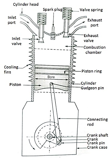


Fig. IC Engine


Components of IC Engine

  • Cylinders: A cylinder in an I.C engine has to withstand very high pressure upto 70 bar and temperature upto2500 0c, because the combustion of fuel is carried out within the cylinders.
  • Materials used are cast iron or alloy steel.

    Cylinder is provided with a cylinder lines on the inner side and a cooling arrangement on outside.


    2.     Piston: The function of piston is to transmit the gas force to connecting rod and hence to the crank. It slides in the cylinder.

    It is made up of cast steel or aluminium steel.


    3.     Piston ring: Two or more piston rings made up of cast steel are provided.

    They seal the space between the cylinder lines and piston, to preventleakage of high-pressure gases from cylinder to crank case.


    4.     Crank Shaft: It runs under the action of piston through the connecting rod and crank pin and transmits the power from piston to drive shaft.

    It is made up of medium carbon steel.


    5.     Crank: Crank is an integral part of the crank shaft. It is a rotating member and makes circular motion in the crank case.

    It’s one end is connected to crank shaft and another end is connected with a connecting rod.


    6.     Connecting rod: It is a link between the piston and crank. It transmits the reciprocating motion of piston to the continuously rotating crank pin during working stroke and vice versa during other strokes.

    It is made up of carbon steel.


    7.     Exhaust Manifold: Exhaust manifold is system of pipe, which connects the exhaust port of various cylinders to a common exhaust system for the engine.


    8.     Inlet Port: Through inlet port, the charge is sucked into the cylinders.


    9.     Exhaust Port: Through exhaust port, the exhaust gases from the cylinder are expelled out to the atmosphere.


    10. Gudgeon pin/ Piston Pin: It is made up of hardened steel in the shape of spindle. It connects the piston to the smaller end of the connecting rod.


    11. Governor: It is run by a drive from crank shaft. Its function is too regular the quantity of charge to maintain the engine speed constant, even though there is variation in load on engine.


    12. Water Cooled Jacket: The cylinder is surrounded by means of water-cooled jacket, to dissipate the heat evolved during combustion.


    13. Flywheel: It is a wheel mounted on the crank shaft, which stores excess energy produced during power stoke. This excess energy is given back by flywheel, which is utilises in running the idle strokes (Power consuming) such as suction, compression and exhaust.


    14. Spark Plug: Its function is to ignite the mixture after completing the compression stroke in petrol engine.

    It is generally mounted in the cylinder head. Spark Plug is used in case of petrol engine.


    15. Fuel pump: It force the fuel at high pressure through fuel nozzle into the cylinder at the end of compression stroke diesel engines


    16. Fuel Nozzle: The function of fuel nozzle is to break up the oil into the fine spray, when it enters the cylinder of diesel engines.


    17. Carburettor: It is provided in the petrol engines for preparation of a homogeneous mixture of air and fuel (petrol).


    Four stroke cycle Petrol Engines

    Construction:
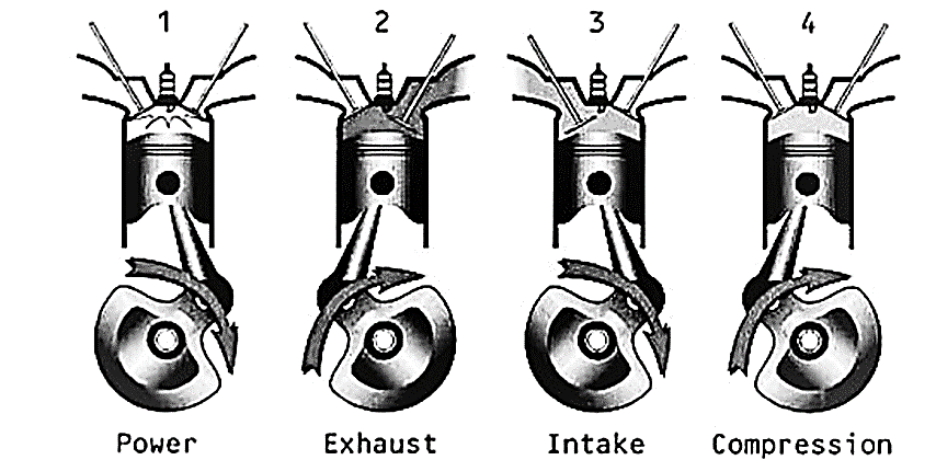
  • A piston reciprocates inside the cylinder.
  • The piston is connected to the crank shaft by means of a connecting rod and crank. The inlet and exhaust valves are Mounted on the cylinder head.
  • A spark is provided on the cylinder Head.
  • The fuel used is petrol.
  •  

  • The mixture of air fuel is sucked into the cylinder through the inlet valve.
  • Compression Stroke: (Second Stroke of the piston)
  • Piston moves up from BDC to TDC • Both inlet and exhaust valves are closed. • The air fuel mixture in the cylinder is compressed.

  • Working or Power or Expansion Stroke: (Third Stroke of the Engine)
  • The burning gases expand rapidly. They exert an impulse (thrust or force) on the piston. The piston is pushed from TDC to BDC • This movement of the piston is converted into rotary motion of the crankshaft through connecting rod. • Both inlet and exhaust valves are closed.

  • Exhaust Stroke: (Fourth stroke of the piston)
  • Piston moves upward from BDC • Exhaust valve is opened and the inlet valve is closed. • The burnt gases are forced out to the atmosphere through the exhaust valve (Some of the burnt gases stay in the clearance volume of the cylinder) • The exhaust valve closes shortly after TDC • The inlet valve opens slightly before TDC and the cylinder is ready to receive fresh charge to start a new cycle.


  • Bore: Bore is defined as inside diameter of cylinder.
  •  

    2.     Stroke: Stroke is defined as the distance travelled by piston from one dead crank to another dead centre.


    3.     Top Dead Centre:

    In case of vertical engine, the topmost position of piston towards cover end side of cylinder is called as top dead centre. In case of horizontal engines. It is known as inner dead centre.


    4.     Bottom Dead Centre:

    In case of vertical engines, the lowest position of piston towards the crank end side of cylinder is called as bottom dead centre. In case of horizontal engine, it is known as outer dead centre.


    5.     Clearance Volume:

    Clearance Volume is defined as the volume contained in the cylinder above the top of piston, where the piston is at TDC.

    It is denoted by Vc.


    6.     Swept Volume:

    Swept volume is defined as the volume swept by position when it moves from TDC to BDC or BDC to TDC

    Swept volume is also called as stroke volume or displacement volume. It is denoted Vs.

    Mathematically

    = . . L


     where, D= Bose Or Diameter of cylinder in ‘m’

     L= Length of Stroke in ‘m’


    7.     Total Volume:

    Total Volume is defined as “the volume contained in the cylinder above the top of piston, when the piston is at BDC”

    Total volume is the algebraic sum of swept volume and clearance volume. It is denoted by V.

    V=Vs + Vc


    8.     Compression Ratio:

    Compression ratio is defined as “the ratio of total cylinder volume to clearance volume.


    r = =


    9.     Cut of Ratio:

    Cut of ratio is defined as “the ratio of volume inside the cylinder at the end of heat supplied to the volume of before heat supplied.


    10. Piston Speed:

    Piston Speed is defined as “The distance travelled by Piston in one minute.

    Piston Speed = 2 x L x N


    L = Length of Stroke in ‘m’

    N = Engine Speed in ‘m’


    I.C. Engines may be classified as.

    1. According to cycle of operations

    a) Two stroke cycle engines, b) From stroke cycle engines


    2. According to cycle of combustion

    a) Off Cycle   b) Diesel cycle   c) Dual cycle


    3. According to arrangement of cylinder

    a) Horizontal engine   b) Vertical Engine   c) V-type engine 

    d) Radial engine 


    4. According to type of fuel used

    a) Oil engine       b) Petrol engine   c) Gas engine   d) Kerosene engine   e) Diesel Engine


    5.  According to speed (r.p.m) of engine

    a) Low speed      b) Medium speed      c) High speed


    6. According to method of ignition

    a) Spark ignition (S. I Engine) b) Compression ignition (C.I Engine)


    7. According to method of cooling the engine cylinder.

    a) Air cooled engine   b) Water cooled engine


    8. According to method of governing

    a) His and miss governing   b) Quality governing 

    c) Quantity governing


    9. According to number of cylinders:

    a) Single cylinder engine   b) Multi cylinder engine


    10. According to Suction pressure

    a) Naturally aspirated engine    b) Supercharged engine


    a)     IC Engine

    Type     Application

    i)                   Gasoline Engine    Automotive, Marine, Aircraft


    ii)                 Gas Engine    Industrial Power


    iii)              Diesel Engine     Automotive Railways, Power,

    Marine

    iv)               Gas Turbines    Power, Aircraft, Industrial,

    Marine


    b)    EC Engine


    Type     Application

    i)                   Steam Engines    Locomotives, Marine


    ii)                 Staring Engine    Experimental Space, Vehicles


    iii)              Steam Turbines     Power, Large, Marine


    iv)               Close cycle Gas Turbine Power, Marine


    Intake system

    This system allows fresh air to enter the engine. Its main parts are

  • Air cleaner:
  • It is a device which cleans & filterers the air before entering the combustion chamber of an engine.
  • The operating efficiency, good performance & durability of an engine depend mainly upon its cleaner.
  •  

    2.     Supercharger:

  • A super charger is a device for increasing the air pressure into engine so that more fuel can be burned & the engine output increased.
  • The pressure inside the manifold of a supercharged engine will be greater than the atmospheric pressure.
  • Supercharged air is either provide by positive displacement rotary blowers or by centrifugal blowers.
  •  

    3.     Inlet manifold:

  • The inlet manifold is required to deliver into the cylinder either a mixture of a fuel & air from the carburettor or only air from air cleaner.
  • The inlet manifold is made in one- or two-pieces wither from cast iron or aluminium alloy.
  • The manifold flanges are connected to the cylinder block or cylinder head by means of asbestos, copper gasket, studs & nuts.
  •  

    Exhaust system

    The exhaust system collects gases from the engine & expels them out. The system consists of exhaust manifold, turbocharger & muffler.

  • Exhaust manifold
  • the exhaust manifold collects exhaust gases from the exhaust ports of various cylinder & conducts them from each end to central exhaust passage.
  • It is usually made of cast iron.
  • The exhaust manifold is design to avoid overlapping of exhaust stroke as much as possible thus keeping the back pressure to a minimum.
  •  

    2.     Turbocharger

  • This is an exhaust driven turbine which drives a centrifugal compressor wheel.
  • The compressor is located between the air cleaner & intake manifold, while the turbine is located between the exhaust manifold & muffler.
  •  

    3.     Muffler

  • The muffler reduces noise of the exhaust gases by reducing the pressure of the used gases by slow expansion & cooling.
  • The muffler contains a number of chambers through which the gas flows.
  • The gas is allowed to expand from the first passage into a much larger second one & then to a still lager third one & so on, to the final & largest passage which is connected to tail pipe of a muffler.
  •  


  • Actuating mechanism is the combination of parts that receives power from the drive mechanism and transmits the power to the engine valves. In order for the intake and exhaust valves, fuel injection, and air start to operate, there must be a change in the type of motion.
  • The rotary motion of the camshaft must be changed to a reciprocating motion. The group of parts that, by changing the type of motion, causes the valves of an engine to operate is generally referred to as the Valve actuating mechanism.
  • A valve-actuating mechanism may include the camshaft, cam followers, pushrods, rocker arms, and valve springs.
  • In some engines, the camshaft is so located that pushrods are not needed. In such engines, the cam follower is a part of the rocker arm.
  •  


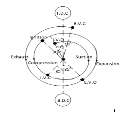
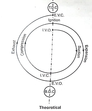
    Valve Timing Diagram Four Stroke Petrol engine

  • In actual practice, it is difficult to open and close the valve instantly.
  • So, for getting better performance of engine, the valve timings are modified.
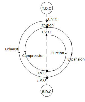
    D 2.png

    Theoretical                                                              Actual

  • Inlet valve open 200 before TDC to enable fresh change to enter the cylinder and at same time, to help the exhaust gases to escape to atmosphere.
  • The inlet value closes between 300 -400 after BDC.
  • Suction of air-fuel mixture a continued during this and after it, compression of entrapped mixture starts.
  • Ignition starts at 300 before TDC, so that, fuel gets more time to burn.
  • Exhaust value opens between 300 – 400 before BDC, so that, the exhaust gases are driven out of cylinder. Exhaust value closes at 100 after TDC.
  •  

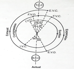
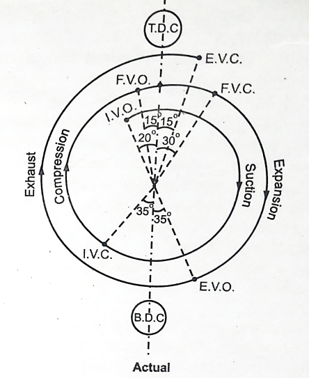
    Valve Timing Diagram for Four Stroke Diesel Engine
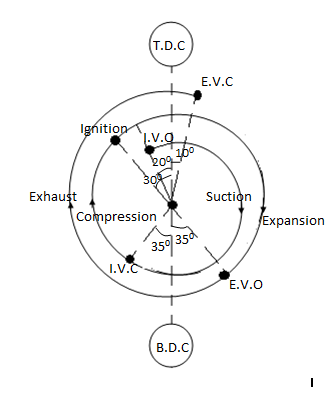
  • In actual practice, it is difficult to open and close the valve instantly, so for getting better performance of the engine, valve timing is modified.
  • A 22.jpg


  • Inlet valve opens 200 before TDC to enable fresh air to enter the cylinder and to help exhaust gases to escape to atmosphere at same time.
  • Also, inlet valve closes between 300 – 400 after BDC and the sucked air is compressed further.
  • Fuel injector valve opens at 150 before TDC to spray the fuel (diesel) in the compressed air to ignite the same.
  • Fuel injector value closes at 300 after TDC and fuel supply is made cut off.
  • Exhaust value opens between 300 – 400 before BDC, so that, gases are driven out of cylinder.
  • Exhaust value closes between 100 – 200 after TDC.
  •  

  • Type of sensor
  • i)                   Crank angle sensor

    A permanent magnet inductive signal generator is mounted in closed proximity to the flywheels, where it radiates a magnetic field.

    As the flywheel spins and pins are rotated in the magnetic field, an alternating (AC) waveform is delivered to the ECU to indicate speed of rotation.

    ii)                Air flow sensor (AFS)

    Air flow sensor is mounted between the air filter and the throttle body. As air flows through the sensor, it deflects a wave or flap, which wipes a potentiometers resistance track and therefore, it changes the resistance of the track to generate a variable voltage signal.

    iii)             Manifold absolute pressure (MAP) sensor

    MAP sensor measurer the manifold vacuum or pressure and the matured value. Is converted into electrical signal by transducer. Electrical signal is return to the ECU. It changes as manifold pressure changes. ECU uses this information to measure engine load, so that, ignition timing can be advance or retarded as required.

    iv)              Throttle position sensor (TPD):

    TPS it's provided to inform the ECU of idle position, rate of deacceleration and acceleration and wide-open throttle (WOT) condition.

    Single of sensor is used by the computer to enrich the fuel Mixture during acceleration and the advance or retard the ignition timing

    v)                 Oxygen sensor (OS)

    An oxygen sensor is ceramic device place in the exhaust manifold of the engine side of catalytic converter.

    The oxygen sensor returns a single to the ECU, which can almost instantaneously adjust the duration of fuel injection.

    vi)              Coolant temperature sensor (CTS)

    CTS is usually located on the cylinder head or intake manifold.

    It is used to monitor temperature of engine coolant.

    Resistance of CTS is proportional to coolant temperature.

    Single of CTS inform to computer, when engine is warm.

    vii)           Ignition timing sensor (ITS)

    Here, the change is magnetic field due to movement of piston causes generation of a square pulse.

    This square pulse is fed to the ECU, which activates the ignition coil and spark is produced at appropriate time.


    2.8.1 Air – standard cycles

    The operating cycle of an IC engine can be broken down into a sequence of separate processes:

  • Intake, Compression,
  • Combustion,
  • Expansion and
  • Exhaust
  • Actual IC Engine does not operate on ideal thermodynamic cycle that are operated on open cycle.

    Basic Air Standard/Ideal Cycles:

  • Air standard cycles are idealized cycles based on the following approximations/assumptions:
  • The working fluid is assumed to be a perfect gas (air as ideal gas) and follows:
  • PV = m*R*T

  • No change in the mass of working media.
  • No Heat loses from the system to surroundings.
  • All the processes are internally reversible.
  • Heat assumed to be supplied from a cont. temp heat source and not form chemical reaction/burning of fuel.
  • Heat rejection is used to restore fluid to initial state.
  • Working medium has Const. specific heats throughout the cycle.
  •  

    2.8.2 Fuel air cycles and actual cycle

    Fuel Air Cycles

  • The actual cycles which taken into account the variations of specific heats, the molecular structure & the mixtures of fuel & air approximating to actual engine working substance, are called as fuel air cycles.
  • The analysis of fuel air cycles leads into to closer approach to actual performance of the engine compared to air standard cycles.
  •  

     Assumptions in fuel – air cycles

  • Subsequent to combustion process the mixture is in chemical equilibrium.
  • The intake & exhaust process are both at atmospheric pressure
  • Compression & Expansion process are both adiabatic without friction.
  • The change in kinetic energy is negligible.
  • The mixture of air & fuel is homogeneous & burns instantaneously.
  • There is no chemical change in either fuel or air prior to combustion.
  • In case of reciprocation engine, it is assumed that fluid motion can ignored inside the cylinder.
  •  

    Actual Cycle

  • The actual cycles for IC engine differ from the fuel air cycles & air standard cycles in many respects.
  • The actual cycle efficiency is much lower than the air standard efficiency due to various losses occurring in the actual engine operation.
  •  


    Effect of Variables on engine performance.

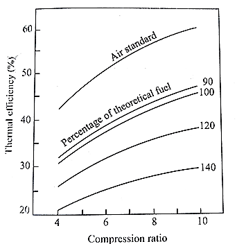
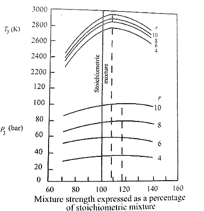
    a)     Compression Ratio
  • The fuel air cycle efficiency increases with the compression ratio in the same manner as the air standard cycle efficiency
  • Maximum pressure & temperature increases with compression ratio.
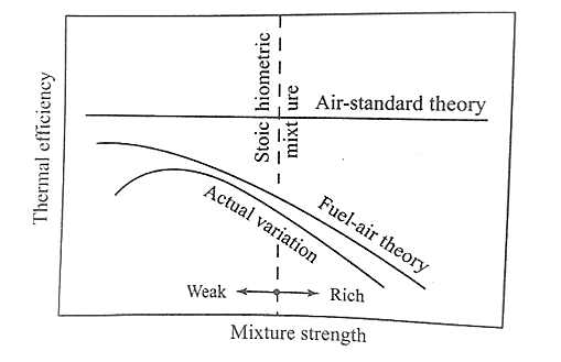
  • b)    Fuel air Ratio: On efficiency

  • Slightly lean mixture result in lower temperature rise & lower specific heats
  • Further it will lower the losses due to dissociation, the efficiency is therefore higher.
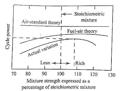
  • c)     Fuel air ratio: On maximum power

  • Maximum power at stoichiometric condition.
  • As the mixture becomes richer, after certain point both efficiency & power output falls.
  • This is because in addition to higher specific heats & chemical equilibrium losses there is direct wastage of fuel.
  •  

    d)    Fuel air Ratio: On maximum temperature
  • The temperature after combustion reaches a maximum when the mixture is slightly rich.
  • At stoichiometric condition, some O2 left due to dissociation effect, hence, slightly rich mixture will result in more fuel to combine with O2
  • Further, enriching the charge will decreases the maximum temperature due to dissociation effect.
  • e)     Fuel air ratio: Maximum pressure

  • The pressure of gas depends upon its temperature & number molecules.
  • Therefore, effect of fuel air ratio on maximum pressure is similar to maximum temperature.
  •  

    f)       Fuel air Ratio: On exhaust Temperature
  • Maximum exhaust temperature occurs at stoichiometric condition as fuel & air are completely used & dissociation effect is less.
  • Exhaust temperature is less at rich & lean mixture & decreases with compression ratio.
  •  

    g)    Fuel Air Ratio: On mean effective pressure.
  • The mean effective pressure increases with compression ratio.
  • Maximum mean effective pressure occurs at slightly which fuel air ratio similar to the case of maximum combustion temperature.
  •  


    Actual Cycle:

  • The actual cycles for IC engine differ from the fuel air cycles & air standard cycles in many respects.
  • The actual cycle efficiency is much lower than the air standard efficiency due to various losses occurring in the actual engine operation.
  •  

    Losses in Actual Cycles:

    A)    Time Losses:

  • In actual cycles combustion is not instantaneous. Entire process of combustion takes a definite time interval & during this period of combustion the gases experience change in volume
  • The increased volume due to motion of & piston results in lower maximum pressure & less work on the piston & lower’s the efficiency.
  •  

    B)    Heat Losses:

  • The ideal compression & expansions processes were assumed to be adiabatic.
  • However, in actual processes there is heat transfer from the working substance to the cylinder.
  • These losses are called heat losses which lowers the efficiency by reducing work.
  •  

    C)   Exhaust Blow down losses:

  • If the exhaust valve is opened at the bottom dead centre, the piston has to do work against high cylinder pressure.
  • In actual cycle exhaust valve is opened at 500 before BDC.
  • It helps in reducing pressure in the cylinder.
  • Due to this lot of heat energy is carried away by exhaust gases resulting into loss of work.
  • These losses are called exhaust blow down losses.
  •  

    D)   Pumping Losses:

  • In actual cycle during suction stroke pressure is lower than the atmospheric pressure & during exhaust stroke pressure is higher than the atmospheric pressure.
  • Therefore, some work is done on the charge & gases during suction & exhaust strokes.
  • This work is called pumping losses.
  •  

    E)    Rubbing friction losses:

  • These losses are due to friction between the piston & the cylinder walls, friction in various bearing & also the energy required in operating the auxiliary equipment.
  • The friction losses increase by small extent due to increase in mean effective pressure.
  •  


    Sr No

    Air Standard Cycle

    Fuel Air Cycle

    Actual Cycle

    1

    Working substance is pure air

    Working substance is mixture of fuel & air

    Working substance is mixture of fuel & air

    2

    Heat is added by heat reservoirs.

    Heat is added due to combustion of fuel & air

    Heat is added due to combustion of fuel & air

    3

    Specific heat of gases does not change with temperature.

    Specific heat of gases changes with temperature

    Specific heat of gases changes with temperature

    4

    There is no change in chemical composition.

    There is change in chemical composition.

    There is change in chemical composition.


    5

    The heat is supplied at constant volume in case of Otto cycle

    Burning of fuel & air takes place at constant volume

    Burning of fuel & air is not at constant volume

    6

    Compression & expansion processes are isentropic

    Processes are not adiabatic.

    Heat losses are considered.

    7.

    Valves open & close instantaneously

    There is time lag in opening & closing valve

    There is time log in opening & closing valve.

    8

    Suction & exhaust stroke are eliminated.

    Suction & exhaust stroke are at atmospheric pressure

    Suction is at below atmospheric pressure & exhaust is at above atmospheric pressure

    9

    Friction is neglected.

    Friction is neglected.

    Friction is considered.


    Reference:

    1) V. Ganesan: Internal Combustion Engines, Tata McGraw-Hill

    2) M.L. Mathur and R.P. Sharma: A course in Internal combustion engines, Dhanpat Rai

    3) H.N. Gupta, Fundamentals of Internal Combustion Engines, PHI Learning Pvt. Ltd.


    Index
    Notes
    Highlighted
    Underlined
    :
    Browse by Topics
    :
    Notes
    Highlighted
    Underlined