Back to Study material
AT

Unit – 5

Engine Systems and Alternative Fuels


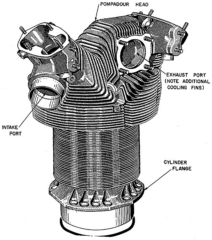
Air cooled engines are those engines, in which heat is conducted from the working components of the engine to the atmosphere directly. The cylinder of an air-cooled engine has fins to increase the area of contact of air for speedy cooling.

The amount of heat dissipated to air depends upon:
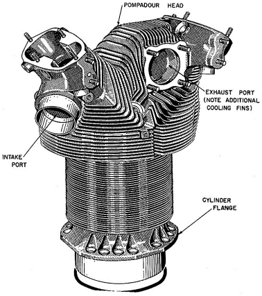
  • Amount of air flowing through the fins.
  • Fin surface area.
  • Thermal conductivity of metal used for fins.
  • Great diagram of air cooling fins!!! | Engraving illustration, Air, Cool  stuff

    Fig. Air Cooling Fins 


    Merit & Demerits of Air-Cooling System

    MERITS:

  • It is simpler in design and construction.
  • Water jackets, radiators, water pumps, thermostat, pipes, hoses etc. are not needed.
  • It is more compact.
  • It is comparatively lighter in weight.
  • DEMERITS:

  • There is uneven cooling of engine parts.
  • Engine temperature is generally high during working period.
  •  


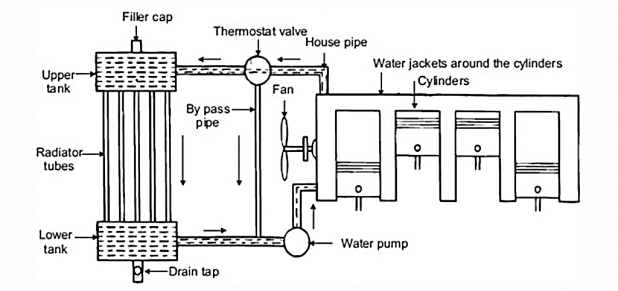
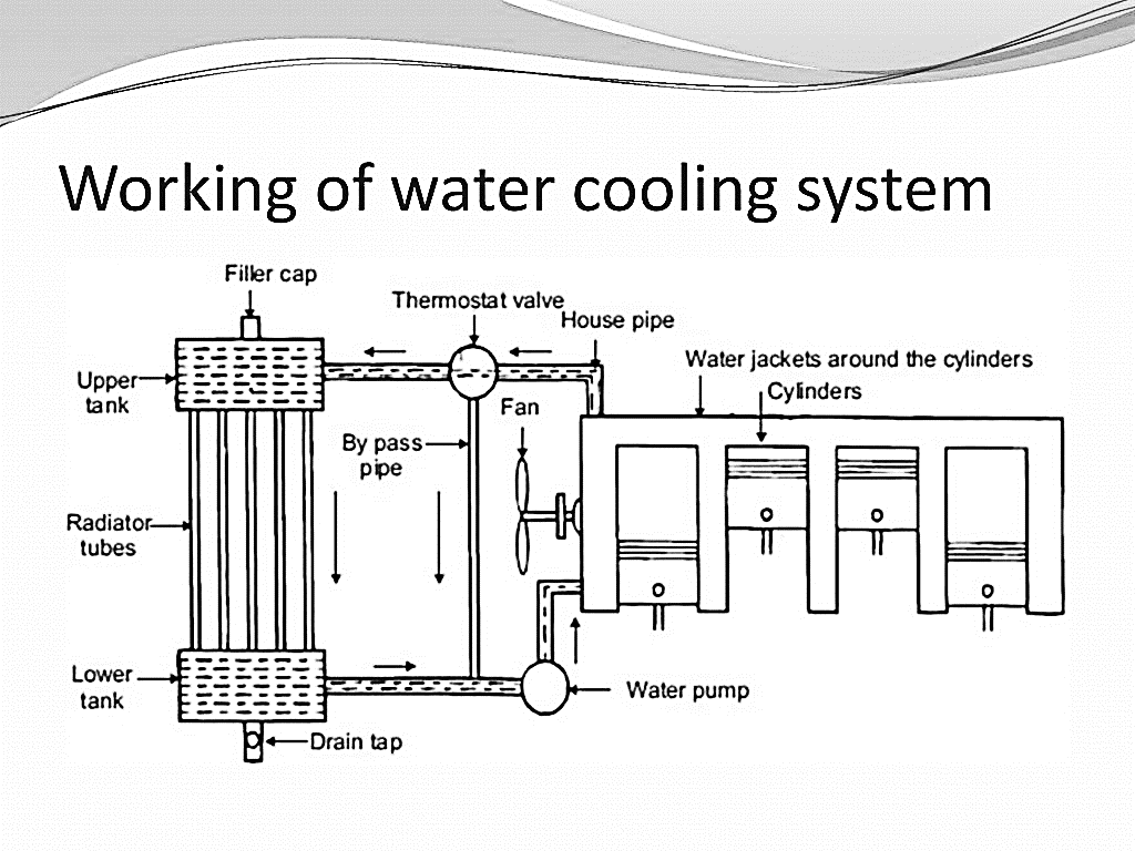
  • A liquid is circulated around the cylinders and absorb heat from the cylinder walls and cylinder head.
  • Coolant absorbs heat as it passes through the engine and also lubricates the water pump.
  • Hot coolant enters the radiator in which the heat is passed on to air that is flowing through the radiator.
  • Working of Water-Cooling System:

    THE COOLING SYSTEM. - ppt download

    Merits & Demerits of Liquid Water-Cooling System:

    MERITS:

  • Uniform cooling of cylinder, cylinder head and valves
  • Specific fuel consumption of engine improves by using water cooling system
  • If we employ water cooling system, then engine need may not be provided at the front end of moving vehicle.
  • Engine is less noisy as compared with air cooled engines, as it has water for damping noise
  • DEMERITS:

  • It depends upon the supply of water.
  • If the water-cooling system fails then it will result in severe damage of engine
  • The water-cooling system is costlier as it has a greater number of parts.
  •  


  • To reduce the friction between moving parts
  • To increase the efficiency
  • To minimize the vibrations
  • To reduce the corrosion and carbon deposits
  • To reduce the heat of moving parts
  • To minimize power loss due to friction
  • To reduce the noise created by moving parts
  • To provide cooling to the engine
  •  


  • Viscosity:
  • It is a measure of the resistance to flow of an oil.
  • It is measured in Saybolt universal Seconds (SUS).
  • It is expressed in centistokes, centipoises and redwood seconds.
  •  

    2.     Viscosity Index:

  • Viscosity of oil decreases with increase in temperature.
  •  

    3.     Cloud point:

  • If an oil is cooled, it will start solidifying at some time.
  • Temperature at which oil starts solidifying, is called cloud point.
  • 4.     Pour point:

  • It is temperature just above which the oil sample will not flow under certain prescribed conditions.
  • This property is important for operation of engines and substances at low temperature conditions.
  •  

    5.     Flash point and Fire point

  • The temperature at which vapour of an oil flash when subjected to a naked flame is called flash point.
  • Fire point is the temperature at which the oil, it once lit with flame, will burnt steadily at least for 5 seconds.
  •  

    6.     Specific Gravity:

  • It varies between 0.85 to 0.96.
  • 7.     Acidity:

  • Oil must have low acidity.
  • 8.     Carbon residue:

  • It is quantity of carbaneous residues which remains after evaporation of a sample oil under specific conditions.
  • 9.     Oiliness:

  • It is property of oil to cling to the metal surface by molecular action and then to provide a very thin film under lubrication conditions.
  • This property affects start of engines.
  •  


  • Solid Lubricants : e.g., Graphite, molybdenum, mica.
  • Semi-solid Lubricants : e.g., Heavy greases.
  • Liquid Lubricants: e.g., Mineral oil obtained by refining petroleum oil, vegetable oils obtained from olive, linseed, caster and animal oil.
  • The various lubrication systems used for internal combustion engine may be classified as:
  •  

    Mist Lubrication System

  • This system is used where crankcase lubrication is not suitable.
  • In two – stroke engine, as the charge is compressed in the crankcase, it is not possible to have the lubricating oil in the sump. Hence, mist lubrication is adapted in practice.
  • In such engine, the Lubricating oil is mixed with the fuel. The usual ratio being 3 % to 6 %
  • The oil and the fuel mixture are inducted through the carburetor.
  • The fuel is vaporized and the oil in the form of mist goes via the crankcase into the cylinder.
  • The oil which strikes the crankcase walls lubricates the main and connecting rod bearings, and the rest of the oil lubricates the piston, piston rings and the cylinder.
  • The advantage of this system is its simplicity and low cost as it does not require an oil pump, filter.
  • Disadvantages are as below.
  • 1)It causes heavy exhaust smoke, due to busing of lubricating oil partially or fully and also forms deposits on piston crown and exhaust ports which affect engine efficiency.

    2)Since the oil comes in close contact with acidic vapors produced during the combustion process gets contaminated and may result in the corrosion of bearing surface.

    3) This system calls for a through mixing for effective lubrication. This requires either separate mixing prior to use or use of some additive to give the oil good mixing characteristics.

    4) During closed throttle operation as in the case of the vehicle moving down the hill, the engine will suffer from insufficient Lubrication as the supply of fuel is less.


    Wet sump Lubrication System

  • In the wet sump system, the bottom of the crankcase contains an oil pan or sump from which the lubricating oil is pumped to various engine components by a pump.
  • After Lubricating these parts, the oil flows back to the sump by gravity.
  • Again, it is picked up by a pump and recirculated through the engine lubricating system.
  • There are three varieties in the wet sump lubrication system.
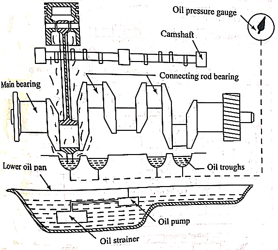
  • i)                   Splash System:

  • This type of lubrication system is used in light duty engines.
  • A schematic diagram of this system is shown in fig.
  • The Lubricating oil is charged into in the bottom of the engine crankcase and maintained at a predetermine level.
  • The oil is drowned by a pump and delivered through a distributing pipe extending the length of the crankcase into splash through located under the big end of all the connecting rods.
  • These through were provided with overflows and the oil in the through are therefore kept at a constant level.
  • A splasher or dipper is provided under each connecting rod cap which dips into the oil in the trough at every revolution of the crankshaft and the oil is splashed all over the interior of the crankcase, into the piston and onto the exposed position of the cylinder walls.
  • A hole is drilled through the connecting rod cap through which oil will pass to the bearing surface.
  • Oil pockets are also provided to catch the splashing oil over all the main bearings and also over the camshaft bearing.
  • From the pockets the oil will reach the bearings surface through a drilled hole.
  • The oil dripping from the cylinder is collected in the sump where it is cooled by the air flowing around the cooled oil is then recirculated.
  •  

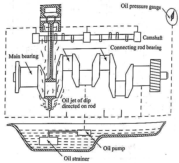
    ii)                The Splash and Pressure Lubrication System:
  • This system is shown in Fig: where the Lubricating oil is supplied is under pressure to main and crankshaft bearing.
  • Oil is also supplied under pressure to pipes which direct a stream of oil against the dippers on the big end of connecting rod bearing cup and thus the crankpin bearings are lubricated by the splash or spray of oil thrown up by the dipper.
  •  

    iii)             Pressure Feed System:

  • The pressure feed system is illustrated in fig. in which oil is drawn in from the sump and forced to all the main bearings of the crankshaft through distributing channels.
  • A pressure relief valve will also be fitted near the delivery point of the pump which opens when the pressure in the system attains a predetermined value.
  • An oil hole is drilled in the crankshaft from the center of each crankpin to the center of an adjacent main journal through which oil can pass from the main bearings to the crankpin bearing.
  • Fig. Pressure Feed System

  • From the crankpin it reaches piston pin bearing through a hole drilled in the connecting rod.
  • The cylinder walls, tappet rollers, piston and piston rings and connecting rod bearings. The basic components of the wet sump lubrication systems are i) Pump ii) Strainer iii) Pressure regulator iv) filter v) breather
  •  

    Dry sump Lubrication system

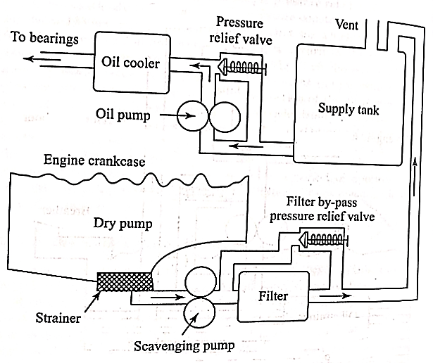
  • A dry sump lubricating system is illustrated in fig.
  •  In this, the supply of oil is carried in an external tank.
  • An oil pump draws oil from the supply tank and circulates it under pressure to the various bearings of the engine.
  • Oil dipping from the cylinders and bearings into the sump is removed by a scavenging pump which in turn the oil is passed through a filter and is fed back to the supply tank.
  • Thus, oil is prevented from accumulating in the base of the engine.
  • The capacity of the scavenging pump is always greater than the oil pump.
  • Fig. Dry sump lubrication system


  • In this system is filter with a bypass valve is placed in between the scavenge pump and the supply tank.
  • If the filter is clogged, the pressure relief valve opens permitting oil to by – pass the filter and reaches the supply tank.
  • A separate oil cooler with either water or air as the cooling medium, is usually provided in the dry sump system to remove heat from the oil.
  •  


    This system is an internal-combustion engine that produces the spark to ignite the mixture of fuel and air which includes

  • The battery,
  • Ignition coil,
  • Distributor,
  • Spark plugs, and
  • Associated switches and wiring.
  • Construction:

    It consists of the following parts:

  • Battery (Lead Acid type): Stores the Electrical Energy. Charges using the Dynamo driven by the engine.
  • Ignition switch: Helps in turning the system ON or OFF.
  • Ballast Resistor: Under prolonged conditions it helps to maintain the temperature of Ignition Coil.
  • Ignition coil: Steps up the Low Voltage to High Voltage to induce an electric spark in the spark plug.
  • Contact breaker: Making and breaking the primary circuit.
  • Capacitor: Prevents the burning and possible welding of metal points.
  • Distributor: Distributes the Ignition surge to individual spark plugs.
  • Spark plug: Creates the spark due to ionization of gap.
  • Working:

  • Ignition switch is turned on, the current starts flowing through primary circuit. This current sets up a magnetic field around the soft iron core of the ignition coil.
  • When the breaker points open, the current which was flowing through the contact breaker starts flowing through the condenser
  • As the condenser charges, the primary current falls and the magnetic field collapses.
  • This change in the magnetic field induces a current in the primary winding which flows in the same direction as the primary current and changes the condenser to a voltage much higher than battery voltage thus stooping the current flow from the battery.
  • Due to this, the condenser then discharges into the battery, thus reversing the direction of both primary current and magnetic field.
  • This rapid collapse and reversal of the magnetic field induces a very high voltage in the secondary winding of the ignition coil.
  • This high voltage is then carried through the high-tension wires to the distributor rotor, where it passes through one of the ignition harnesses into the spark plug and produces a spark.
  • Advantages:

  • Moving parts are absent-so no maintenance.
  • Contact breaker points are absent-so no arcing.
  • Spark plug life increases by 50% and they can be used for about 60000 km without any problem.
  • Better combustion in combustion chamber, about 90-95% of air fuel mixture is burnt compared with 70-75% with conventional ignition system.
  • More power output.
  • More fuel efficiency.
  • Disadvantages:

  • Because of arcing, pitting of contact breaker point and which will lead to regular maintenance problems.
  • Poor starting: After few thousands of kilometers of running, the timing becomes inaccurate, which results into poor starting (Starting trouble).
  • At very high engine speed, performance is poor because of inertia effects of the moving parts in the system.
  • Sometimes it is not possible to produce spark properly in fouled spark Ignition Systems plugs.
  •  


    The purpose of an ignition system is to provide sufficient electrical voltage to discharge a spark plug at precisely the right time to ignite highly compressed air-fuel mixture.

    Magneto Ignition systems provide current for ignition without any outside primary source of electricity.
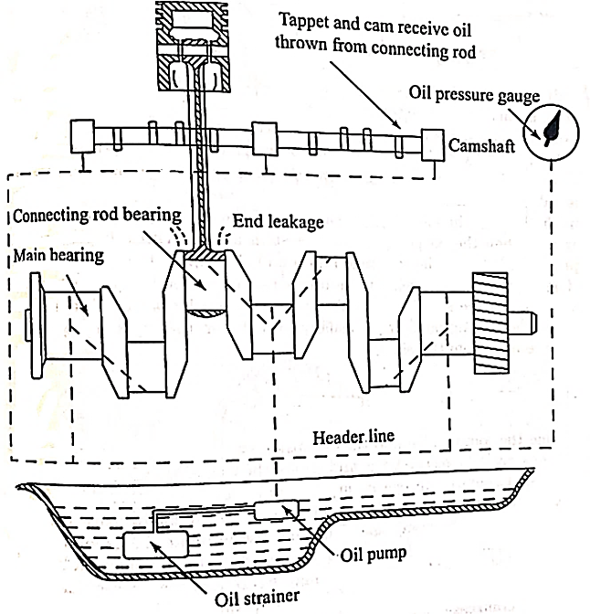
    Fig. Magneto Ignition system


    The magneto is the source of energy generation in the magneto ignition system. it’s typically a small generator that works on electricity as it produces a voltage when rotated by the engine. This is to say, the higher the rotation, the greater the voltage produced by the system. The system has no external source of energy and does not need one to start it, the magneto itself is a source for generating energy.

    The winding in the system is of two types which include;

  • Primary binding and;
  • Secondary binding
  • Depending on the engine rotation, the magneto is of three types;

  • Magnet rotating type
  • Armature rotating type
  • Polar inductor type
  • The difference between the three is just their source of rotation. In the magnet type, the armature is stationary while the magnets rotate around the armature. Whereas in the armature type, the armature rotates between the stationary magnet. Finally, in the polar inductor type, both the magnet and the windings remain stationary but the voltage is generated when the flux field is reversing. This is achieved with the help of soft iron polar projections which is known as inductors.

    Distributor:

    The distributor components used in the magneto ignition system can also be found in the multi-cylinder engine. This multi-cylinder engines are used for the regulation of spark in the right sequence in the spark plug. It causes the surge of the ignition to be distributed uniformly among the spark plugs.

    Carbon brush type distributor:

    In the gap type distributors, the electrode of the rotor arm is close to the distributor cap but is in contact. This eliminates the occurrence of wear in the electrode. While in the carbon brush type, the rotor arm sliding over the metallic segment carries the carbon brush that is placed inside the distributor cap or molded insulating material. With this, an electric connection is created with the spark plug.

    Spark plug:

    The spark plug is a device that is powered by the ignition system to ignite the fuel-air mixture in the cylinder. It has two electrodes that are parted from each other which allow a high voltage to flow through it. These electrodes are made of steel shell and an insulator. The central electrode is attached to the supply of the ignition coil and an outer steel shell. It’s grounded insulating them.

    Capacitor:

    A capacitor is also a component in the magneto ignition system. it’s just like the conventional electrical capacitor with two metal plates separated by an insulating material with a distance. Air is commonly used as insulating material on this system, but to reach a particular technical requirement, a high-quality insulating material is employed. The function of this capacitor is to store charge.

    Different Types of Magneto ignition system:

  • MBI – Mechanical Breaker Point Ignition
  • CDI – Capacitive Discharge Ignition
  • TCI – Transistor Controller Ignition
  •  


    Capacitive Discharge Ignition:

  • CDI is a solid-state ignition system; it is one of the newest ignition systems used.
  • CDI is a breaker less and the moving mechanical parts are replaced with electronic components.
  • The only moving parts are the flywheel of the magnets.
  • Advantages to TCI:

  • As with CDI, the only moving parts are the magnets on the flywheel.
  • The timing of TCI is more precise with the use of the Transistors.
  • Does not use Mechanical Breaker contacts, but utilizes semi-conductors instead.
  • Transistor Controller Ignition:

  • As the Flywheel magnets rotate, they pass by the ignition coil in the system.
  • The magnetic field of the magnets induce current in the primary windings of the ignition coil creating the charge for the spark.
  • Advantages to TCI:

  • As with CDI, the only moving parts are the magnets on the flywheel.
  • The timing of TCI is more precise with the use of the Transistors.
  • Does not use Mechanical Breaker contacts, but utilizes semi-conductors instead.
  •  


    If start of combustion is too early work is done against piston and if too late then peak pressure is reduced. The optimum spark timing that gives the maximum brake torque, called MBT timing occurs when these two opposite factors cancel.
    Purpose of spark advance:

  • Spark advance increases with higher engine speeds for performance and fuel economy.
  • Spark advance needs to decrease under heavy load conditions to avoid detonation.
  •  


    Supercharging

  • Method of supplying air or fuel - air mixture higher than the pressure at which the engine naturally aspirates, by means of boosting device is called the supercharging.
  • The device which booststhe pressure is called supercharger.
  •  

    Method of supercharging


  •  Electrical motor driven supercharger
  • In this type of compressor is driven independently usually by an electrical motor.
  • The speed of the supercharger can be varied independent of engine speed and therefore control comparatively easier.
  •  

    2.     Ram effect of supercharging.

  • The Ram effect of supercharging system consist primarily of tuned inlet pipes.
  • These pipes induce resonant harmonic air oscillations. the kinetic energy of these oscillations provides are ramming effect.
  • For the efficient operation of this system, the engine Speed must be kept constant.
  •  

    3.     Under piston supercharging.

  • Under piston method of supercharging has so for been confined too large marine four stroke engine of the crosshead type.
  • It utilizes the bottom side of the piston for compressing the air.
  • The bottom ends of the cylinder are closed off and provided with suitable valves.
  • This system gives an adequate supply of compressed air as there are two delivery strokes to each suction stroke of the cycle.
  •  

    4.     Kadenacy system of supercharging

  • The Kadenacy system utilizes the energy in the exhaust system to cause depression of pressure in the cylinders.
  • The depression makes the scavenge air to flow into the cylinder.
  • A blower may also be used with this system, but it is not an essential.
  • The Kadenacy system is based on the following principal: when the exhaust ports or valves are opened rapidly during the end of expansion stroke, there is, within the first interval of a few thousands second, an urgeor impulse in the gases to escape very rapidly from the cylinder.
  • The escaping gases leave behind the pressure depression at the above moment, the fresh change of air is allowed to enter the cylinder behind the exhaust gases by suitable timing off the admission valve or ports.
  • For the best result of proper timing and skillful design of the exhaust system is must.
  •  

    Effects of supper charging

  • Higher power output
  •  Greater inductions of charge mass
  • Better atomization of fuel
  • Better mixing of fuel and air
  • Better scavenging of products
  • Better torque characteristics over a whole speed range
  •  Quicker acceleration of vehicles
  •  More complete and smoother combustion
  • Inferior or poor ignition quality fuel usage.
  • Smoother operation and reduction in diesel knock tendency
  • Increase detonation tendency in SI engines
  • Improved cold starting
  • Reduced exhaust smoke.
  •  

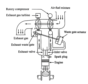
    Turbo charging

  • In turbo charging, the supercharger being driven by a gas turbine which uses the energy in the exhaust gases.
  • There is no mechanical linkage between the engine and the supercharger.
  • The major parts of turbo charger are turbine wheel, turbine housing, turbo shaft, compressor wheel, compressor housing and bearing housing.
  • During engine operation hot exhaust gases blowout through the exhaust valve opening into the exhaust manifold.
  • The exhaust manifold and the connecting tubing route these gases into the turbine housing.
  • As the gases pass through the turbine housing, they strike on the fins or blades on the turbine wheel when the engine load is high enough, there is enough gas flow, and this makes the turbine wheel to spin rapidly.
  • The turbine wheel is connected to the compressor wheel by the turboshaft.
  • U 2.png

    Fig. Turbo charging

  • As such, the compressor wheel rotates with the turbine which sucks air into the compressor housing centrifugal force throws the air outward.
  • This causes the air to flow out of the turbocharger and into the engine cylinder under pressure.
  • In the case of turbo-charging, there is a phenomenon called turbo lag.
  • It refers to short delay period before the boost or manifold pressure increases.
  • This is due to the time the turbocharger assembly takes the exhaust gases to accelerate the turbine and compressor wheel to speed up.
  • In the turbocharger assembly, there is a control unit called waste gate.
  • This unit limits the maximum boost pressure to prevent detonation in SI engine and the maximum pressure and engine damage.
  •  


    Bio-diesel

    Biodiesel refers to a non-petroleum-based diesel fuel consisting of short chain alkyl (methyl or ethyl) esters, made by Transesterification of vegetable oil or animal fat, which can be used (alone, or blended with conventional petrol-diesel) in unmodified diesel-engine vehicles.

    "Biodiesel" is standardized as mono-alkyl ester.

    Ethanol

  • It is commonly called alcohol, ethyl alcohol, and drinking alcohol.
  • The principal type of alcohol found in alcoholic beverages, produced by the fermentation of sugars by yeasts.
  • It is a neurotoxin, psychoactive drug, and one of the oldest recreational drugs. It can cause alcohol intoxication when consumed in sufficient quantity.
  • Ethanol is a volatile, flammable, colorless liquid with a slight chemical odor. • Empirical formula is C2H5OH
  • LPG 

    Liquefied Petroleum Gas (LPG) or Auto Gas is a generic name for mixtures of hydrocarbons (Generally Combination of the gas is 70% butane (C4H10), 30% propane (C3h8)) which exists as vapor under ambient conditions and can be changed into liquid state by applying moderate pressures.

    When stored under pressure it becomes a dense liquid allowing large quantities of gas to be stored in a relatively small space. Energy content similar to gasoline. Inherently clean burning characteristics.

    LPG, known world over as Auto gas, gives you a new life as it brings along multiple benefits. Auto gas is the 3rd most popular automotive fuel and the number # 1 clean fuel alternative in the world.

     2 C4H10 + 13 O2 8 CO2 + 10 H2O + heat C3H8 + 5 O2 3 CO2 + 4 H2O + heat

    CNG and Hydrogen: Compressed Natural Gas (CNG)

    PREPARATION:

    It is made by compressing the natural gas(composed of methane) to less than 1% of the volume at standard atmospheric pressure. It is stored in hard cylindrical containers at a pressure of 200-280 bars.

    IMPORTANCE:

  • It is cheap than other fuels.
  • It is dispersed quickly when released.
  • It is lighter than air.
  • It releases less carbon into the atm.
  • ADVANTAGES:

  • Due to absence of lead or Benzene, lead fouling of spark plugs is eliminated.
  • Low maintenance cost than other vehicles Increases the life of lubricating oils.
  • It mixes easily and evenly in air.
  • It is less likely ignite on hot surfaces, because it has a high auto ignition temp.(540˚c), and small range of flammability (5%-15%).
  • Less pollution and more efficiency.
  • Hydrogen:

    Hydrogen has three naturally occurring isotopes, denoted 1H, 2H, and 3H. Other, highly unstable nuclei (4H to 7H) have been synthesized in the laboratory but not observed in nature.

    Hydrogen burns readily in air at a very

    The enthalpy of combustion is 286 kJ/mol

    2 H2 + O2 2 H2O + 572 kJ

    Hydrogen/oxygen mixtures are explosive and ignites spontaneously in air, is 560 °C

    Hydrogen gas (dihydrogen) is highly flammable and will burn in air at a very wide range of concentrations between 4% and 75% by volume. The enthalpy of combustion for hydrogen is 286 kJ/mol:

    2 H2(g) + O2(g) 2 H2O(l) + 572 kJ (286 kJ/mol)

    Hydrogen/oxygen mixtures are explosive across a wide range of proportions. Its autoignition temperature, the temperature at which it ignites spontaneously in air, is 560 °C (1,040 °F).


    Reference:

    1) V. Ganesan: Internal Combustion Engines, Tata McGraw-Hill

    2) M.L. Mathur and R.P. Sharma: A course in Internal combustion engines, Dhanpat Rai

    3) H.N. Gupta, Fundamentals of Internal Combustion Engines, PHI Learning Pvt. Ltd.


    Index
    Notes
    Highlighted
    Underlined
    :
    Browse by Topics
    :
    Notes
    Highlighted
    Underlined