Unit – 6
Compressor
Working Principle:
Construction:
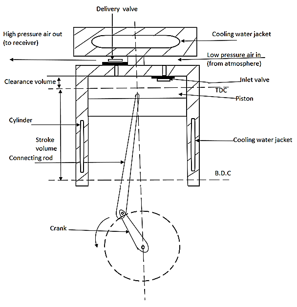
Fig. Single stage Reciprocating Air Compressor
Working:
a). Suction Stroke:
b). Compression Stroke:
Computation of work done
Expression for work done on air in a reciprocating compressor without clearance.
A P-V diagram of a reciprocating compressor without clearance has been shown in fig.
Process 0-1 Constant pressure suction
Process 1-2 Polytrophic compression of air
Process 2-3 Constant pressure delivery.
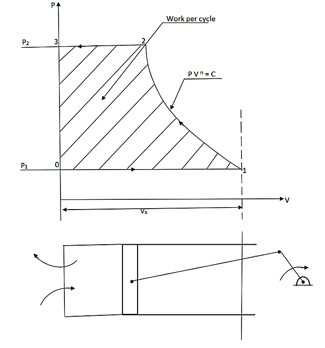
Fig. P-V diagram of a reciprocating compressor without clearance
Work transfer will be given by area under the curve on P-V diagram.
Work transfer per cycle = - --- (1)
For process 1-2
PVn = C
Vn = C/P
V =  where K = C1/n
:. Put in eqn (1)
Work transfer per cycle = -
= 
= - K [ P-1/(n + 1) / -1/n + 1 ]P2P1
= - K * [ P2-1/(n + 1) – P1-1/(n + 1) ]
=  [ V2P21/n. P2-1/n. P2 – V1P11/n. P1-1/n. P1]
=  [ P2V2 – P1V1]
Hence,
Work done on the airper cycle=  [ P2V2 – P1V1]
=  P1V1[
P1V1[ ]
]
=  P1V1[
P1V1[  (
( )-1/n– 1. . . (
 ) = (
) = ( )-1/n
)-1/n
= P1V1[
P1V1[ - 1]
- 1]
= mRT1[
mRT1[ - 1]
- 1]
Expression for work done on air in a reciprocating compressor with clearance.
The P-V diagram of reciprocating compressor with clearance is shown fig.
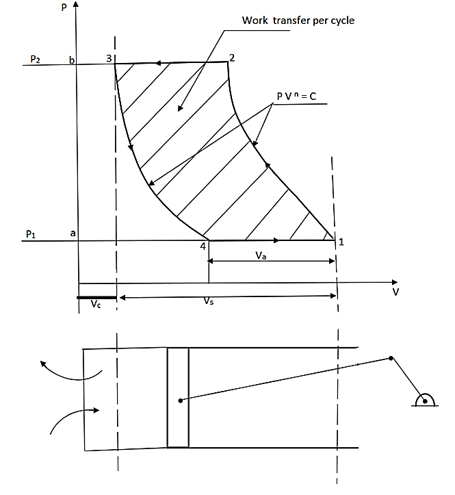
Fig. P-V diagram of reciprocating compressor with clearance
Work transfer = area (a – 1 – 2 – b - a) – area (a – 4 – 3 – b - a)
per cycle
= {  x P1V1 x [ (
 )(n-1)/n - 1]} – {
  x P4V4 x [ (
 )(n-1)/n - 1]}
= {  P1V1[ (
 )(n-1)/n - 1]} – {
  P1V4 [ (
 )(n-1)/n - 1]}
=  P1 (V1 – V4) [ (
 )(n-1)/n - 1]
=  P1Va [ (
 )(n-1)/n - 1]
=  maRT [ (
 )(n-1)/n - 1]
It is defined as the ratio of actual volume of air sucked in per cycle to the swept volume per cycle.
ɳv = 
= 
= 
= 
= 1- 
= 1- 
= 1-  ……… k = clearance ratio.
=1- k[( )1/n -1] (
 ) = (
) = ( )1/n
)1/n
It is defined as ratio of isothermal power to the indicated power. It is also called as compressor efficiency.
Isothermal efficiency = 
ɳiso =  ..Single stage compressor
ɳiso =  .. Doublestage compressor
1). If clearance volume is large, it will delay the opening of inlet valve. Therefore, amount of air sucked per stroke will be reduced.
2). Due to clearance volume, the actual volume of air sucked per stroke is less than swept volume. Therefore, volumetric efficiency decreases.
3). More power is required to drive the compressor for same pressure ratio, due to increase in volume to be handled.
4). High compression pressure value is limited due to clearance volume & we obtain low compression ratio.
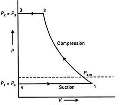
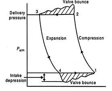
Theoretical Indicator Diagram Actual Indicator Diagram
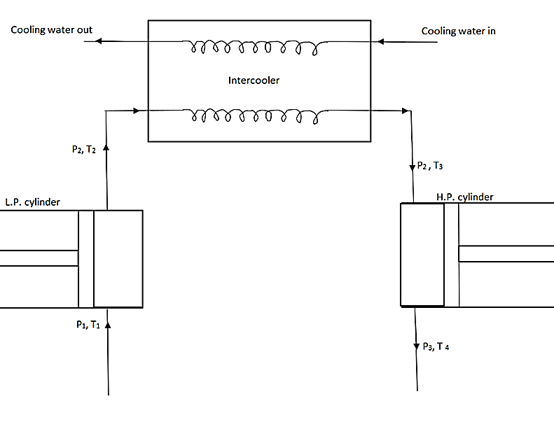
Fig. Multi staging of compressor
Computation of work done of Multi- stage compressor:
Work required for two stage reciprocating air compressor with inter cooler.
Work done in L.P. Cylinder
W1 =  P1V1 [ (
 )(n-1)/n - 1 ]
Work done in H.P. cylinder
W2 =  P2V2 [ (
 )(n-1)/n - 1 ]
Total work done,
W = W1 + W2
= {  P1V1 [ (
 )(n-1)/n - 1 ] } + {
  P2V2 [ (
 )(n-1)/n - 1] }
=  { P1V1 [ (
 )(n-1)/n - 1 ] + P2V2 [ (
  )(n-1)/n - 1 ] }
When intercooling is complete,
P1V1 = P2V2
W =  . P1V1 {(
  )(n-1)/n + (
  )(n-1)/n - 2 }
Consider a two-stage compressor, with intercooler incorporated in between.
When intercooling is complete
Work required by compressor,
W =  P1V1 [(
  )(n-1)/n + (
  )(n-1)/n– 2]……….. (1)
Least value of intermediate pressure P2 may be obtained by differentiating the above equation with respect to P2.
Value of P2 obtained denotes the pressure of the intercooler at which work required to drive the compressor is minimum.
Thus work required is minimum when
 = 0
= 0
 [
[  . P1V1 [ (
  )(n-1)/n + (
  )(n-1)/n - 2] ] = 0
put  = a (constant)
 [ aP1V1 [ (P2/P1)a + (P3/P2)a - 2 ] ] = 0
aP1V1 [ (1/P1)aa. P2a-1 + P3 (-a)( P2 )-a-1 ] = 0
aP1-a P2a-1 – aP3a P2-a-1 = 0
a(P1)-a (P2)a-1 = a P3a . P2-a-1

P2a-1 . P2a+1 = P3a . P1a
P22a = (P3P1)a
P22 = P3P1
P2 = 
Or
P2/P1 = P3/P2 = (P3/P1)1/2
Put this value in eqn (1)
W =  P1V1 [ (
  )(n-1)/n + (
  )(n-1)/n - 2]
=  P1V1 [ (
 )(n-1)/n - 1 ]
=  P1V1 [ (
 )(n-1)/2n - 1 ]
a). Complete Inter-cooling
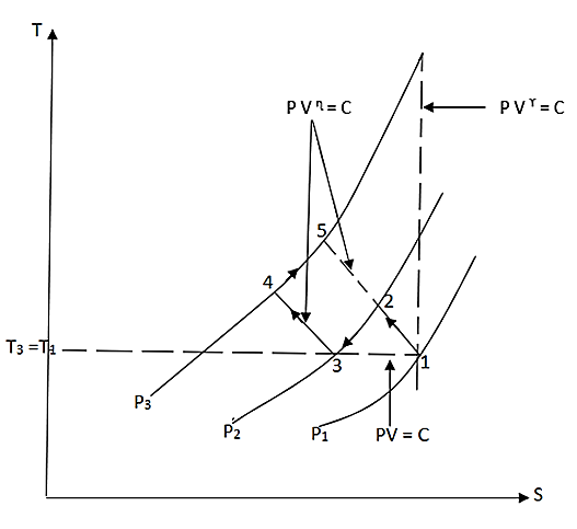
b). Incomplete or Imperfect Inter-cooling:
(PV = C) as shown in Fig.
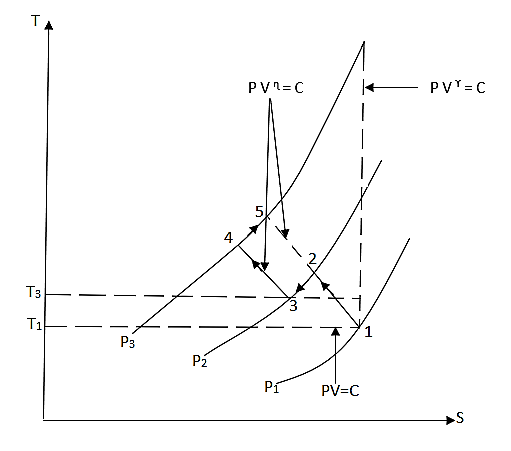
Functions of After-cooler:
a). To cool the discharged air leaving the compressor.
b). To reduce the risk of fire. (For example: hot compressed air pipes can be a source of ignition).
c). To reduce moisture level or amount of water vapour in the compressed air.
d). To protect the downstream equipment’s (i.e., equipment’s installed after compressor in a process plant) from excessive heat.
a). By pass control: -
b). Inlet Valve Unloaders:
c). Clearance pocket: -
d). Stepless Capacity Control: -
e). Variable Speed drive: -
Working Principle:
Construction:
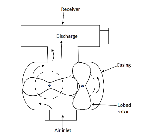
Fig. Lobe type or Roots blower Type Compressor
Applications of Lobe type or Roots Blower Compressor:
Working Principle:
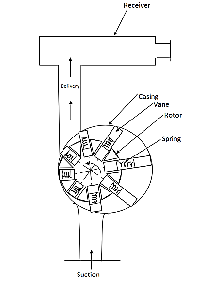
Fig. Vane type rotary compressor
Applications of Vane type compressor:
Screw Compressor:
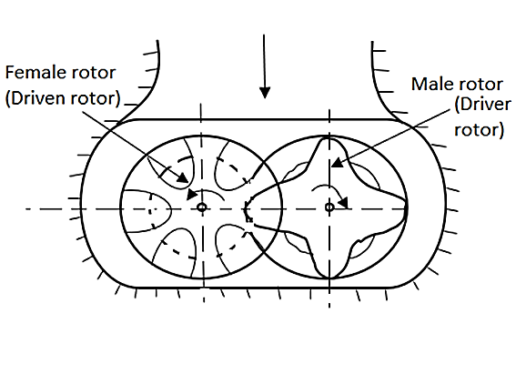
Fig. Screw compressor
Advantages of Screw Compressor: -
Scroll Compressor:
A scroll compressor is a device for compressing air or refrigerant. In rolling stocks, scroll compressor is used for HVAC and brake systems.
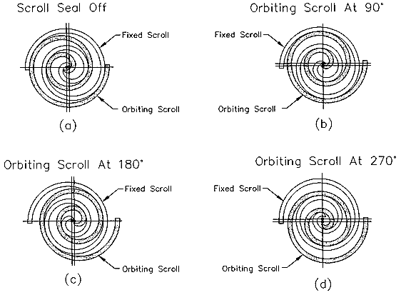
The orbiting scroll is coupled to the crankshaft and orbits, rather than rotates. The orbiting motion creates a series of gas pockets traveling between the two scrolls. On the outer portion of the scrolls, the pockets draw in gas, and then move into the center of the scroll, where the gas is discharged. As the gas moves into the increasingly smaller inner pockets, the temperature and pressure increase to the desired discharge pressure.
Advantages:
Disadvantages:
Reference:
1) V. Ganesan: Internal Combustion Engines, Tata McGraw-Hill
2) M.L. Mathur and R.P. Sharma: A course in Internal combustion engines, Dhanpat Rai
3) H.N. Gupta, Fundamentals of Internal Combustion Engines, PHI Learning Pvt. Ltd