Unit – 2
Fluid Statics
To determine pressure at any point in a fluid at rest ‘hydrostatic law ‘is used which states that ‘the rate of increase of pressure in a vertically downward direction must be equal to the specific weight of the fluid at that point.
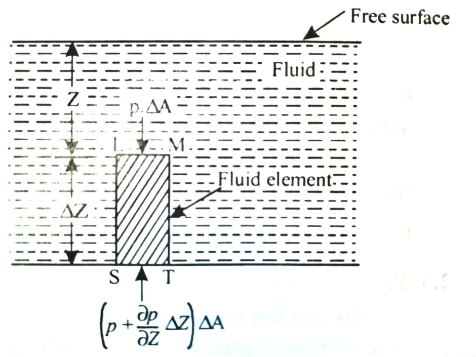
Let p = Intensity of pressure on face LM,
 Cross sectional area of the element,
Z = Distance of the fluid element from free surface,
 Height of the element,
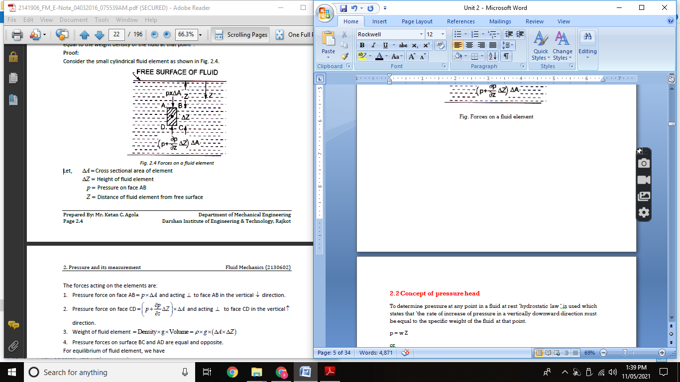
The forces acting on the elements are:
Pressure force on the face LM = p x  ……. acting downward.
Pressure force on the face ST =  x
x  ……. Acting upward
Weight of the fluid element = Weight density x Volume
= w x  x
x 
Pressure forces on the face MT & LS are equal and opposite.
For equilibrium of the fluid element,
 x
x  p x
p x  w x
w x  x
x  = 0
= 0
 - w x
- w x  x
x  = 0
= 0
 = w
= w
Above eqn states that rate of increase of pressure in a vertical direction in equal to weight density of the fluid at that point. This is hydrostatic law.
On integrating above eqn

where p = pressure above atmospheric pressure
Z = pressure head.
w = Specific weight of liquid.
The Pascal’s law states as follows:
The Intensity of pressure at any point in a liquid at rest, is the same in all directions.
Proof Let us consider a very small wedge-shaped element LMN of a liquid as shown in Fig.
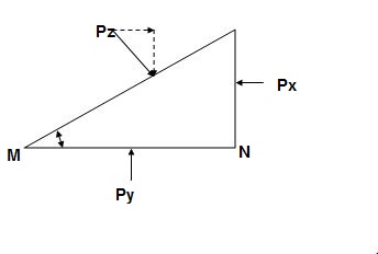
Let px = Intensity of horizontal pressure on the element of liquid.
py= Intensity of vertical pressure on the element of liquid.
pz= Intensity of pressure on the diagonal of the right-angle triangle’s element.
= Angle of the element of the liquid.
Px = Total pressure in the vertical side LN of the liquid.
Py = Total Pressure on the horizontal side MN of the liquid, and
Pz = Total pressure on the diagonal LM of the liquid.
Now Px =pxxLN
and, Py =pyxMN
and, Pz =pzx LM
As the element of the liquid is at rest, therefore the sum of horizontal and vertical components of the liquid pressures must be equal to zero.
Resolving the forces horizontally:
Pz Sin = Px
pz LM Sin = px LN
LM Sin = LN
pz = px
Resolving the forces vertically,
Pz Cos = Py – W
Pz Cos = Py
pz LM cos = py LN
(Where W = weight of the liquid element)
Since the element is very small, neglecting its weight, we have
But, LM Cos = MN
pz = py
We get px = py = pz
Hence at any point in a fluid at rest the intensity of pressure is exerted equally in all directions, which is called Pascal’s Law.
Hydrostatic law: Rate of increase of pressure in vertically downward direction must be equal to the weight density of the fluid at that point
Proof: Consider the small cylindrical fluid element as shown in fig.
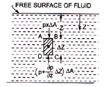
Fig. Forces on a fluid element
A hydraulic ram is a clever device invented over 200 years ago that can pump water uphill with no other external source of power except for the water flowing into it. No, it’s not a free energy device, but if you search around, you’ll find lots great implementations of this style of pump on YouTube, mainly from people doing homesteading and off-grid lifestyle vlogs. And, it’s easy to see why ram pumps have such popularity among these groups. Because if you’ve got a piece of land with an abundant source of water, a ram pump lets you get that water to a tank or location at a higher elevation with a really elegant design that requires no electricity or fuel and only two moving parts. So of course, I built my own so you can see how it works, but first we need to build a just a little bit of foundational knowledge on the behavior of fluids. And this is something anyone can understand.
There are three types of energy that a fluid can have, and in civil engineering, we usually convert them to their equivalents as the height of a static column. This distance is called the head. Understanding the energy in a fluid is how we solve a lot of engineering problems, because in most scenarios, the amount of energy stays the same, and the only thing that changes is what form it takes. The first type is head from gravitational potential. It doesn’t have an equivalent static column because it is a static column. The head is just the distance from an arbitrary datum. This one is easy to demonstrate with a tank and tube. I can move this tube around wherever I want, but the level in the tube and tank are always going to be the same. They’re both exposed to atmospheric pressure at their surface and they’re not moving so there’s no velocity. It’s just pure gravitational potential.
The second type of energy is pressure head. In this case, the head is the pressure divided by gravity and the density of the fluid. So, if I close off the top of my tank and add some air pressure, the level in the tube goes up. The new height is the pressure head, the equivalent static column related to the pressure in the tank. For a given pressure, a denser fluid like mercury will have a lower head compared to a lighter fluid like water because they have different unit weights. A good example of measuring pressure head is a barometer. We live at the bottom of an ocean of air, and we like to keep track of the air pressure down here. One of the easiest ways to do that is to measure how high the pressure can push a static column of a fluid, in most cases mercury.
The final type of energy is velocity head, which relates to a fluid’s kinetic energy. I can demonstrate the equivalent column of water using a tool called a pitot tube. The conversion for velocity head is velocity squared divided by 2 times gravitational acceleration. That’s a lot of background, but it’s important in understanding the function of a ram pump. Because without an external source of power, even though you can go from one type of energy to another, you can’t get more energy out than you had at the start. For example, I can convert a static column of water to one with some velocity, but I’m never going to get the fluid to a higher elevation than where it started… with one exception. An exception that the hydraulic ram pump takes advantage of beautifully.
Concept of pressure head
To determine pressure at any point in a fluid at rest ‘hydrostatic law ‘is used which states that ‘the rate of increase of pressure in a vertically downward direction must be equal to the specific weight of the fluid at that point.
p = w Z
or
Z
where p = pressure above atmospheric pressure
Z = pressure head.
w = Specific weight of liquid.
Air exerts a normal pressure upon all surfaces with which it is in contact, and it is known as atmospheric pressure.
The atmospheric pressure is also known as Barometric pressure.
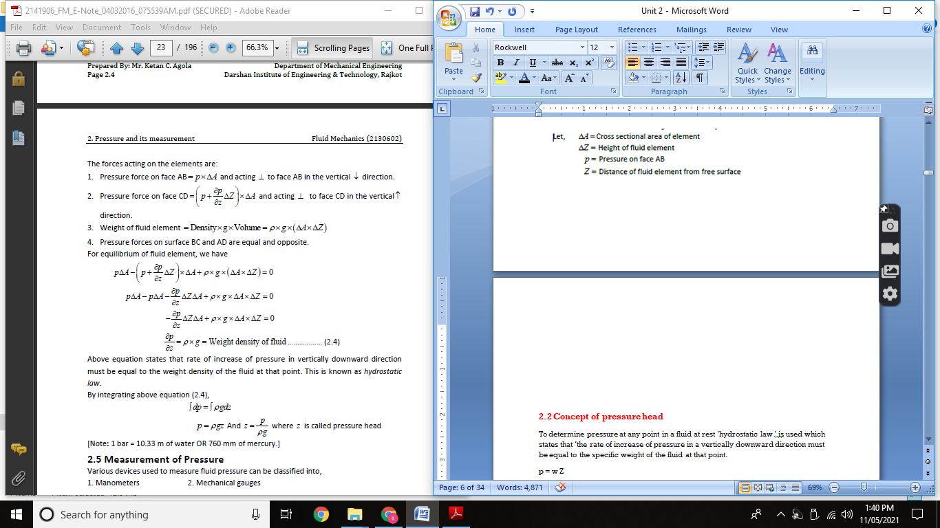
It is the pressure, measured with the help of pressure measuring instrument, in which the atmospheric pressure is taken as datum.
The atmospheric pressure on the scale is marked as zero.
It is necessary to establish as absolute pressure scale which is independent of the changes in atmospheric pressure.
A pressure of absolute zero can exist only in complete vacuum
Any pressure measured above the absolute zero of pressure is termed as an absolute pressure.
Application of the basic equation of hydrostatics
2.5.1 Pressure measuring devices
1. Manometer
Manometer are defined as the devices used for measuring the pressure at a point in a fluid by balancing the column of fluid by the same or another column of liquid.
A “simple manometer” is one which consists of a glass tube whose one end is connected to a point where pressure is to be measured and the other end remains open to atmosphere.
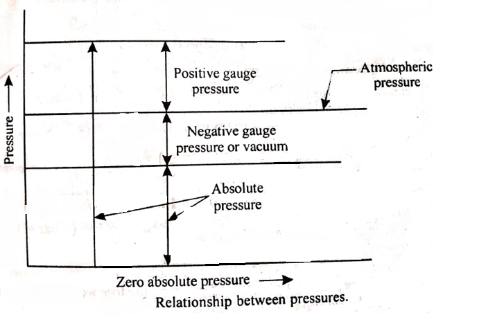
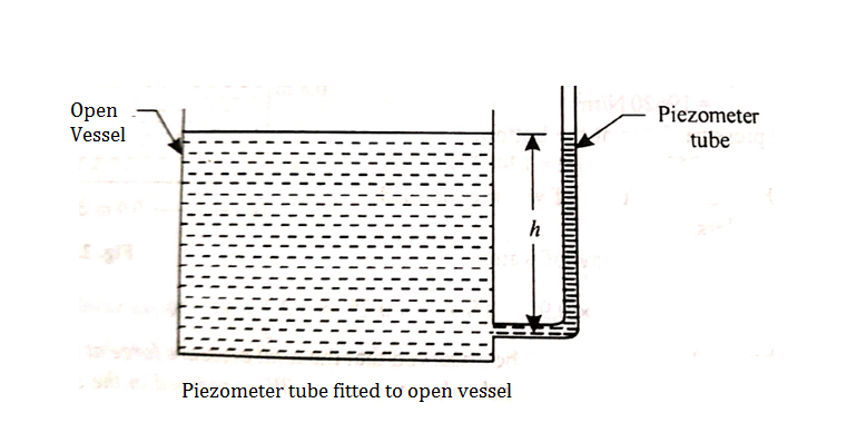
2. Piezometer:
3. Barometer
A barometer is an instrument used to measure air pressure. One way air pressure is measured is in inches of mercury. Air pressure is highest as sea level, making the air also heaviest. At sea level, air pressure is 29.53 inches of mercury. This means that at sea level, it takes 14.7 pounds of pressure per square inch of air to raise mercury in a hollow tube to 29.53 inches in height. What is 14.7 pounds of pressure? Try pushing down on a scale at home until it reads “14.7.” You have exerted 14.7 pounds of pressure on that scale!
A barometer is an instrument that measures the pressure of the atmosphere at a particular location. There are two types: a mercurial barometer which uses mercury, and an aneroid barometer that uses a balloon that expands or contracts when the atmospheric pressure changes.
You may not notice in your experiment that the barometer reading changes in response to temperature as well as direct changes in pressure. Temperature changes pressure, but only in a tightly sealed space (your classroom is not tightly sealed to the outside.) Warmer air taking up the same amount of space as cold air will create more pressure. This is because warm molecules push away from one another instead of moving towards one another. The warm molecules try to take up more space than they have, creating a greater pressure pushing out of the container.
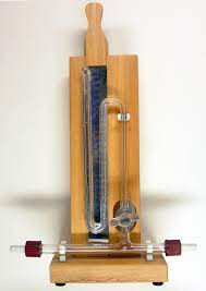
Measuring atmospheric pressure is very important for predicting and preparing for storms. Barometers allow weather forecasters to estimate maximum hurricane wind speeds. Since air is always flowing from high pressure toward low pressure, air moves inward toward the low-pressure center in a hurricane. By using a barometer to find the pressure in the center of the hurricane, forecasters can estimate the fastest wind speeds that the hurricane is capable of producing.
Usually, when barometric pressure (or, pressure as shown on a barometer) falls rapidly, it means a storm is coming. A steady barometer shows stable, fair weather. The barometer saves lives since it helps predict the approach of poor weather. Back when RADAR and satellites didn’t exist, crude barometers were the main way people predicted the approach of bad weather like a hurricane or a major snow storm.
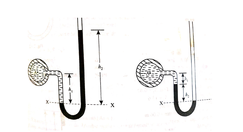
A) Simple Manometer
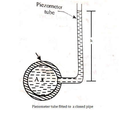
Fig (a) Fig (b)
Let A be the point at which pressure is to be measured. X-X is the datum line as shown in Fig(a)
Let, h1 = height of the light liquid in the left limb above the datum line
h2 = height of the heavy liquid in the right limb above the datum line
h = pressure in pipe, expressed in terms of head
S1 = specific gravity of the light liquid, and
S2 = specific gravity of the heavy liquid
The pressure in the left limb and right limb above the datum line X-X are equal.
Pressure head above X-X line in the left limb = h+h1S1
Pressure head above X-X in the right limb = h2S2
Equating these two pressures, we get

For negative pressure:
Refer to fig(b)
Pressure head above x-x in the left limb= 
Pressure head above x-x in the right limb = 0
Equating these two pressures, we get

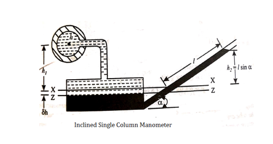
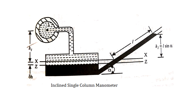
B) Inclined Single Column Manometer:
l = length of the heavy liquid moved in right limb,
 = inclination of right limb horizontal, and
h2 = vertical rise of liquid in right limb from x-x = l sin

C) Differential Manometers
A differential manometer is used to measure the difference in pressures between two points in a pipe or in two different pipes.
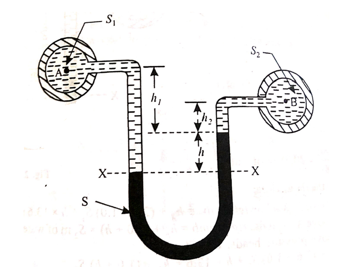
A U-tube differential manometer is shown in fig.
Let, h = difference of mercury level (heavy liquid) in the U-tube,
h1 = distance of the centre of A, from the mercury level in the left limb
h2 = distance of the centre of B, from the mercury level in the right limb,
S1 = specific gravity of liquid in pipe A,
S2 = specific gravity of liquid in pipe B,
S = specific gravity of heavy liquid o mercury
hA = pressure head at A,
hB = pressure head at B
considering the pressure heads above the datum line x-x, we get
Pressure head in the left limb:

Pressure head in the right limb:

Equating the above pressure heads, we get


ii. Inverted U-tube differential manometer:
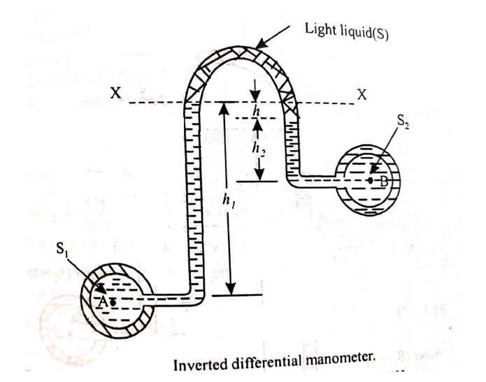
An inverted U-tube differential manometer is shown in fig.
It consists of an inverted U tube, containing light liquid, whose two ends are connected to the points whose difference pressures is to be measured.
Let, h = difference of mercury level (light liquid) in the U-tube,
h1 = Height of liquid in the left limb below the datum line X-X
h2 = Height of liquid in the right limb below the datum line X-X
S1 = specific gravity of liquid in pipe A,
S2 = specific gravity of liquid in pipe B,
S = specific gravity of light liquid
hA = pressure head at A,
hB = pressure head at B
considering the pressure heads below the datum line x-x, we get
Pressure head in the left limb:

Pressure head in the right limb:

Equating the above pressure heads, we get


Vacuum gauges are used to measure the vacuum in the condensers etc. If there is leakage, the vacuum will drop
2.5.2 Micro manometer
Micro-manometers and inclined manometers are modified forms of simple U-tube manometer.
Micro-Manometer
Micro-manometer is also known as single column manometers. The construction of a micro-manometer is as follows:
a. One limb of manometer is a tank of large cross-sectional area as compared to the cross-sectional area of the other limb.
b. This tank acts as a reservoir to hold the manometer fluid.
c. The cross-sectional area of the tank is 100 times greater than that of the other limb.
d. When there is change in the pressure in the pipe, there is negligible change in the level of fluid in tank. This change can be neglected and pressure can be measured as height of liquid in the other column.
It is of two types:
i. Vertical column micro-manometer
ii. Inclined column micro-manometer
Vertical Column Micro-manometer
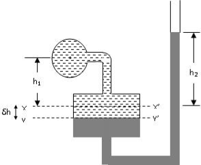
Fig. Vertical column micro-manometer
Initially, when there is no fluid flowing in the pipe the level of manometer liquid is at XX. But due to liquid pressure in the pipe the level of manometer liquid moves down from XX to YY in the tank and rises in the right limb to the distance h2 from XX
Let,
ρ1 = density of liquid for which pressure has to be determined
ρ2 = density of manometer liquid (assume mercury)
S1 = Specific gravity of liquid for which pressure has to be determined
S2 = Specific gravity of manometer liquid
δh = Fall in the level of liquid in the tank
A = Area of cross-section of the tank
a = Area of cross-section of the right limb
h = Pressure head of fluid in the pipe (as head of water)
Therefore:
δhA=a.h2
Pressure in the left limb at YY = 
Pressure in the right limb at YY= 
According to Pascal’s law,

If the cross-sectional area of the tank A is very large compared to cross sectional area of the right limb, then i.e. A >> a, then,
Ratio of a/A will be zero and the above equation can be re-written as:

Inclined column Micro-manometer
Inclined manometers are more sensitive than vertical column manometers. Initially, when there is no fluid flowing in the pipe the level of manometer liquid is at XX. But due to liquid pressure in the pipe the level of manometer liquid moves down from XX to YY in the tank and rises in the right limb to the distance h2 from XX.
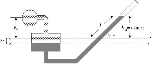
Fig. Inclined column micro-manometer
Let,
S1 = Specific gravity of liquid for which pressure has to be determined
S2 = Specific gravity of manometer liquid
δh = Fall in the level of liquid in the tank
A = Area of cross-section of the tank
a = Area of cross-section of the right limb
h = Pressure head of fluid in the pipe (as head of water)
h1 is the distance from the datum line XX to the centre of pipe
h2 is the height of heavy liquid from the datum line XX in the right limb
 = length of manometer fluid along the right limb
The rise in the manometer fluid in the right limb will be equal to the fall of level in the tank.
From equation for vertical column micro-manometer, we have:

And since h2 = l Sin α

2.6.1 Centre of pressure, total pressure on submerged plane surfaces
Total Pressure
Total pressure is defined as the force exerted by a static fluid on a surface either plane or curved when the fluid comes in contact with the surfaces. This force always acts normal to the surface.
Centre of Pressure
Centre of pressure is defined as the point of application of the total pressure on the surface. There are four cases of submerged surfaces on which the total pressure force and centre of pressure is to be determined. The submerged surfaces may be:
Consider a thin horizontal strip of the surface of thickness dx and breadth b.
Let the depth of the strip be x.
Let the intensity of pressure on strip be p.
p =wx
Total pressure on the strip = p.bdx = wx.bdx
Total pressure on the whole area P =
=w
But  = Moment of the surface area about the liquid level = A
P=wA
Moment of the pressure about free surface OO = (w.x.b. dx).x = w.x2.b. dx
Total Moment, M = 
But  = Moment of inertia of the surface about free surface OO (I0)
Hence, M = wI0
The sum of the moment of the pressure is also equal to P× .
.
P× = wI0
= wI0
wA x
x  = wI0
= wI0
 =
= 
But 
Above eqn becomes


2. Inclined plane surface
Let A = area of the surface
 = depth of the centre of gravity from the free liquid surface.
 =angle at which the immersed surface is inclined with the liquid surface.
w=specific weight of liquid.
Consider a strip of thickness dx width b at a distance l from O.
The intensity of pressure on the strip = wlsin
Area of strip = b.dx
Pressure on the strip =Intensity of pressure × area = wlsin × b.dx
Total pressure on the surface
P = 
But  Moment of surface about OO =
P= = w.
= w.
Let,  = Depth of centre of pressure below free liquid surface
IG = Moment of inertia of the immersed surface about 00.
Moment of pressure about OO = wl × l = wl2
Sum of moments about O
M = 
But  = I0 = Moment of inertia of the surface about point O
M =  Io
Io
Sum of moment of all such pressure about O is also equal to 
 = w
= w Io
Io


Where 
 (
(
= (
( 2)
2)
= +
+ 
3. Curved surface
Consider a curved immersed surface LM submerged in a static fluid as shown in fig.
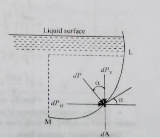
At any point on the curved surface, the pressure acts normal to the surface.
Thus, if dA is the area of a small element of the curved surface lying at a vertical depth of h from surface of the liquid, then total pressure on the elemental area is

This force dP acts normal to the surface. Further integration of above eqn would provide the total pressure on the curved surface and hence

But in case of curved surface the direction of the total pressure on the elementary areas are not in the same direction but varies from point to point.
Thus, the integration of eqn. for curved surface is impossible. The problem however, can be solved by resolving the force P into horizontal and vertical components PH and PV. Then total force on the curved surface is

Hence, the direction of the resultant force P

Where,
PH = Total pressure force on the projected area of the curved surface on vertical plane.
PV = Weight of the liquid supported by the curved surface of liquid.
Practical applications
In designing lock gates in navigation chambers
Curved surface submerged in liquid including numerical on dam gate
1] A rectangle plane surface is 2 m wide & 3 m deep. It lies in vertical plane in water. Determine the total pressure & position of centre of pressure when its upper edge is horizontal & a) Coincides with water surface
b) 2.5 m below the free water surface.
Given
b = 2m
d = 3m
a). Upper edge coincides with water surface
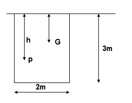
A = b x d = 2 x 3 = 6 m2
X = d/2 -3/2 = 1.5 m
Total Pressure
F = AX
= 9810 x 6 x 1.5
= 88290 N
IG = bd3/12 = 2 x 33/12 = 4.5 m4
Centre of Pressure
h = IG/AX + X = 4.5/ (6 x 1.5) + 1.5 = 2m
b). Upper edge 2.5 m below water surface
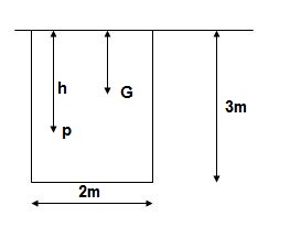
X = 2.5 + 3/2 = 4m
Total pressure F = Ax
= 9810 x 6 x 4
= 235440 N
h = IG/AX + X = 4.5/ (6 x 4) + 4 = 4.1875 m
2]. A heavy car plunges into a lake during an accident & land at the bottom of the lake on its wheel. The door is 1.2 m high & 1m wide, the top edge of the door is 8m below the free surface of the water. Determine total pressure acting on door approximating it as a vertical rectangular plate ¢re of pressure.
Given
b = 1 m
d = 1.2 m
A = b x d = 1 x 1.2 = 1.2 m2
X = 8 + d/2 = 8 + 1/2/2 = 8.6 m
F = AX
= 9810 x 1.2 x 8.6
= 101.24 x 10³ N
IG = bd3/12 = 1 x 1.23/12 = 0.144 m4
h = IG/AX + X = 0.144/ (1.2 x 8.6) + 8.6 = 8.614 m
3]. A circular plate 1.5 m diameter is submerged in water with its greatest & least depth below the surface being 2 m & 0.75 m respectively. Determine total pressure ¢re of pressure.
Given
d = 1.5 m
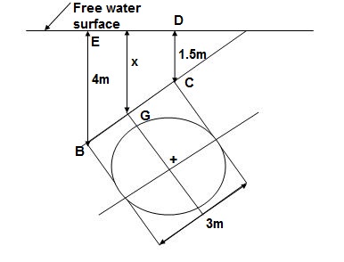
1). A = π/4 x d2 = π/4 x 1.52 = 1.767 m2
2). X = Greatest depth + Least depth / 2
= (2 + 0.75)/2 = 1.375 m
3). F = AX
= 9810 x 1.767 x 1.375
= 28.83 x 10³ N
4). Sin = 1.25/1.5 = 0.833
5). IG = π/64 x d4 = π/64 x 1.54 = 0.248 m4
6). h = IG Sin2/AX + X
0.248 x 0.8332/1.767 x 1.375 + 1.375
= 1.446 m
4]. A triangular plate of 1m base & 1.5 m altitude is immersed in water. The plate is inclined at 300 with free water surface & base is parallel to & at a depth of 2 m from water surface. Find total pressure ¢re of pressure.
Given
b = 1 m
h = 1.5 m
= 300
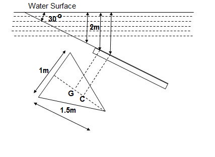
A = ½ x b x h = ½ x 1 x 1.5 = 0.75 m2
X = 2 + 1.5/3 x Sin 30 = 2.25 m
F = AX
= 9810 x 0.75 x 2.25
= 16.55 x 10³ N
IG = bh3/36 = 1 x 1.53/36 = 0.09375 m4
h = IGSin2/AX + X
= 0.09375 x (Sin 30)2/0.75 x 2.25 + 2.25
= 2.264 m
5]. A solid cylinder of diameter 4m and height 4 m. Find the metacentric height of the cylinder if the specific gravity of cylinder is 0.6 and it is floating in water with its axis vertical. State whether the equilibrium is stable or unstable.
Soln. D=4m
H=4m
S=0.6
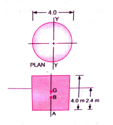
Depth of cylinder in water = 0.6H = 0.6(4) = 2.4m
Distance of centre of buoyancy(B) from A
AB = 2.4 / 2 = 1.2m
Distance of centre of gravity (G) from A
AG = H / 2 = 2m
BG = AG – AB = 2 – 1.2 = 0.8m
I =  4
4
V = Volume of cylinder in water
=
Metacentric height GM = (I / V) – BG
= (12.56/30.16) – 0.8
= -0.383 m
Negative sign means that the metacenter M is below the centre of gravity G. Thus, the cylinder is in unstable equilibrium.
6] A differential manometer is connected to at two points A and B of two pipes as shown in fig. Pipe A contains liquid of specific gravity 1.6, while pipe B contains liquid of specific gravity 0.8. If the pressure at A and B are 11.8×10⁴ N/m² and 19.60× 10⁴ N/m², find the difference in Mercury level in differential manometer.
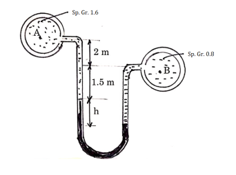
Soln. S1 =1.6
S2 = 13.6
S3 = 0.8
PA = 11.8 ×10⁴ N/m²
PB =19.60× 10⁴ N/m²
h1 = 3.5m h2 = h h3 = h+1.5
PB – PA = w (hB – hA)
19.60× 10⁴ - 11.8 ×10⁴ = 9810 (hB – hA)
hB – hA= 7.95m
Pressure in left limb above datum line = Pressure in right limb above datum line
hA+h1s1+h2s2 = hB+h3s3
h1s1+h2s2-h3s3 = hB - hA
3.5×1.6+h (13.6) -(h+1.5)0.8 = 7.95
h = 0.28m
7] An inverted differential manometer having an oil of specific gravity 0.75 was connected to two different types carrying water under pressure as shown in figure. Determine the pressure in the pipe B in terms of kPa, if manometer reads as shown in figure. Take pressure in the pipe A as 1.5 m of water.
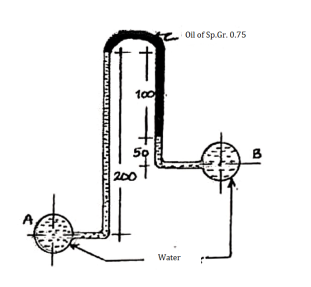
Soln. S1 =1 S2=0.75 S3=1
h1=0.2m h2=0.1m h3=0.05m hA=1.5m
Pressure in left limb below datum line = Pressure in right limb below datum line
hA - h1s1 =hB - h2s2-h3s3
1.5 – 0.2×1 = hB - 0.1×0.75-0.05×1
HB = 1.425m
PB = whB = 9810 ×1.425 = 13979.25 N/m2
2.7.1 Flotation
Whenever a body is immersed wholly or partially in a fluid it is subjected to an upward force which tends to lift it up.
The tendency for an immersed body to be lifted up in the fluid due to an upward force opposite to action of gravity is known as buoyancy.
The force tending to lift up the body under such conditions is known as buoyant force or force of buoyancy.
The magnitude of the buoyant force can be determined by Archimedes principle which states as follows:
“When a body is immersed in a fluid either wholly or partially it is buoyed or lifted up by a force which is equal to the weight of fluid displaced by the body.”
Centre of Buoyancy
The point of application of the force of buoyancy on the body is known as the center of buoyancy. It is always the center of gravity of the volume of fluid displaced.
2.7.2 Stability of bodies:
The stability of a floating body is determined from the position of Meta-centre (M).
a). Stable Equilibrium
If the point M is above G, the floating body will be in stable equilibrium as shown in Fig.
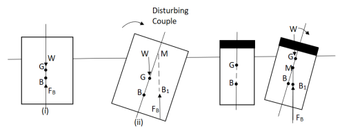
M is above G (stable equilibrium) M is below G (unstable equilibrium)
If a slight angular displacement is given to the floating body in the clockwise direction, the center of buoyancy shifts from B to B1, such that the vertical line through B1 cuts at M.
Then the buoyant force FB through B1 and weight W through G constitute a couple acting in the anti-clockwise direction and thus bringing the floating body in the original position.
Unstable Equilibrium:
If the point M is below G, the floating body will be in unstable equilibrium as shown in fig.
The disturbing couple is acting in the clockwise direction.
The couple due to buoyant force FB and W is also acting in clock direction and thus overturning the floating body.
Neutral Equilibrium:
If the point M is at the center of gravity of the body. The floating body will be in neutral equilibrium.
Stability of submerged Body:
The position of center of gravity ¢er of buoyancy in case of a completely submerged body are fixed.
Weight W acting vertically downward through G, while the buoyant force FB is acting vertical up through B.

Stable Equilibrium
When W = FB& point B is above G, the body is said to be in stable equilibrium.
Unstable Equilibrium:
If W = FB, but center of buoyancy B is below the center of gravity G, the body is in unstable equilibrium.
Neutral Equilibrium:
If W = FB & point B & G are at the same point, the body is said to be in neutral equilibrium.
2.7.3 Meta - Center
It is defined as the point about which a floating body starts oscillating when the body is tilted by a small angle.
The meta-center may also be defined as the point at which the line of action of the force of buoyancy will meet the normal axis of the body when the body is given a small angular displacement.
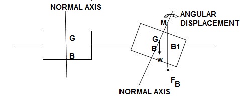
Consider a body floating in a liquid as. Let the body is in equilibrium and G is the center gravity and B is the center of Buoyancy.
Let the body is given a small angular displacement in the clockwise direction as shown in fig. the center of buoyancy, which is the center of the displaced liquid or center of gravity of portion of the body submerged in liquid, will be shifted towards right from the normal axis.
Let it is at B1 as shown in Fig.
The line of action of the force of buoyancy in this position, will intersect the normal axis of the body some point says M.
This point M is called Meta-center.
Meta-Centric Height
The distance MG, the distance between the meta-center of a floating body and the center of gravity of the body is called Meta-centric height.
Determination of Metacentric Height

Let the area of this elementary prism be  A.
A.
The height of this elementary prism is given by x.Ө
The volume of this elementary prism is given by

The upward force or buoyancy for acting at this prism ( is given by

The moment of this buoyancy force about O

For the total portion N’ON, this moment is given by

Or 
Where I = moment of inertia of the sectional area at the waterline about the axis through O.
 gives the change in moment due to buoyancy.

(Where PB = the total force of buoyancy)


Now metacentric height, GM=BM  BG
BG
2. Experimental model


If, l = length of plumb bob, and
d = displacement of the plumb bob,
then, 
and metacentric height is given by,

References:
1. Kundu, Cohen, Dowling, “Fluid Mechanics”, Elsevier India
2. Chaim Gutfinger David Pnueli, “Fluid Mechanics” Cambridge University press.
3. Edward Shaughnessy, Ira Katz James Schaffer, “Introduction to Fluid Mechanics”, Oxford University Press