Unit - 5
Internal & External Flow
When water flows in a pipe, it experiences some resistance to its motion, due to which its velocity and ultimately the head of water available is reduced.
Major energy losses
This loss is due to friction.
Darcy – Weisbach formula
The loss of head in pipes due to friction is calculated from Darcy-Weisbach formula which is given by

where, hf = loss of head due to friction,
f = co-efficient of friction, (a function of Reynolds number, Re)
f =  for Re varying from 4000 to 106
=  for Re < 2000 (laminar/ viscous flow)
L = Length of the pipe
V = Mean velocity of flow, and
D = Diameter of the pipe.
Minor Energy Loses
The minor loss of energy (or head) includes the following cases:
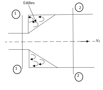
- Consider a liquid flowing through a pipe which has sudden enlargement as shown in fig.
- =


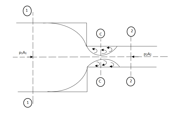
- Consider a liquid flowing in a pipe which has a Sudden Contraction in area as shown in fig.
- =
 [
[ ]2
]2
- This is the loss of energy which occurs when a liquid enters a pipe which is connected to a large tank or reservoir.

- This is the loss of head due to the velocity of the liquid at the outlet of the pipe which is dissipated either in the form of a free jet or it is lost in the tank or reservoir.

- Whenever there is an obstruction in a pipe, the loss of energy takes place due to reduction of the area of the cross-section of the pipe at the place where obstruction is present.
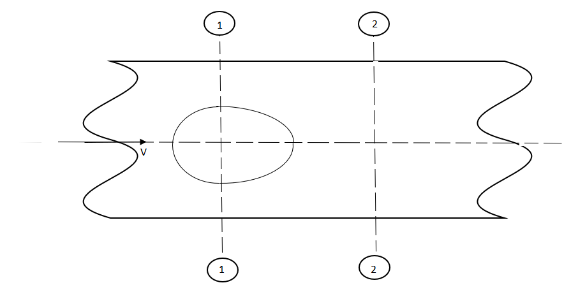
a = Maximum area of obstruction
A = Area of pipe
V = Velocity of liquid in pipe
 [
[  ]2
]2
- When there is any bend in a pipe, the velocity of the flow changes, due to which the separation of the flow from the boundary and also the formation of eddies takes place.

- The loss of head in various pipe fittings such as valves, couplings etc. is expressed as

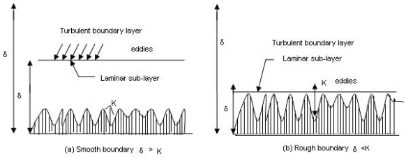
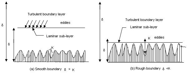
When the average depth k of the surface irregularities is less than laminar sub-layer of the surface δ is called as hydrodynamic ally smooth boundary.
• The eddy which formed outside of the laminar sub-layer try to penetrate in the laminar sub-layer boundary is called as smooth boundary as shown in
• When the average depth k of the surface irregularities is greater than laminar sub-layer of surface δ is called as hydrodynamic ally rough boundary.
• The eddy which formed outside of the laminar sub layer penetrates into the laminar sub-layer. Such boundary is called as rough boundary as shown in.
By Nikuradse’s experiments,
(1) When k / δ < 0.25, smooth boundary.
(2) When k / δ > 6, rough boundary.
(3) When 0.25 < k / δ < 6, transition boundary.
In terms of roughness Reynold’s number,
(1) u.k / v < 4, smooth boundary.
(2) u.k / v > 100, rough boundary.
(3) u.k / v lies between 4 to 100, transition boundary.


Darcy Weisbach Equation
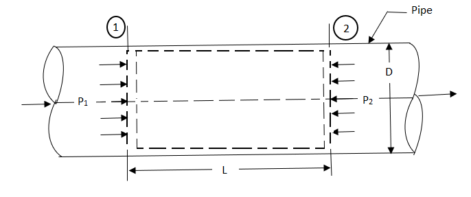
Fig shows a horizontal pipe having steady flow.
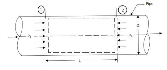
Consider control volume enclosed between section 1 and 2 of the pipes.
p1 = Intensity of pressure at section 1,
p2 = Intensity of pressure at section 2,
L = Length of the pipe, between section 1 and 2,
D = Diameter of the pipe,
f = non-dimensional factor (whose value depends on the material and nature of the pipe surface), and
hf = Loss of head due to friction.
Propelling force on the following fluid between the two section is –
= (p1 – p2) A
(Where, A = area of cross section of the pipe)
Frictional resistance force = f ’ PLV2
Where P = wetted perimeter, and
V = Average flow velocity.
Under Equilibrium condition,
Propelling force = Frictional resistance force
i.e. (p1 – p2) A = f PLV2.
Dividing both sides by weight density W, we have
( ) A =
) A =  PLV2
PLV2
hf =  LV2
LV2
hf = 
=  *
*  *
* 
The ratio  is called the hydraulic mean depth or hydraulic radius, denoted by m (or R).
The term ( ) has dimensions of hf and thus the term
  is a non-dimensional quantity and let us replace it by another constant f.
 ------- 1
In case of a circular pipe,
Hydraulic mean depth, 
Substituting this value in equation 1, we get
 ---------2
(The factor f is known as Darcy coefficient of friction.)
Equation 2 is known as Darcy-Weisbach equation.
Pipes in series
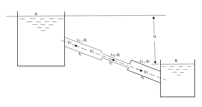
Pipes in series or compound pipes are defined as the pipes of different lengths and -different diameters connected end to end (in series) to form a pipe line as shown in fig.
L1, L2, L3 = Length of pipes 1, 2 and 3 respectively
d1, d2, d3 = diameters of pipes 1, 2, 3 respectively
v1, v2, v3 = velocity of flow through pipes 1, 2, 3
f1, f2, f3 = coefficients of frictions for pipes 1, 2, 3
H = difference of water level in the two tanks
The discharge passing through each pipe is same


The difference in liquid surface levels is equal to the sum of the total head loss in the pipes.

If minor losses are neglected, then above equation becomes as

Pipe in parallel

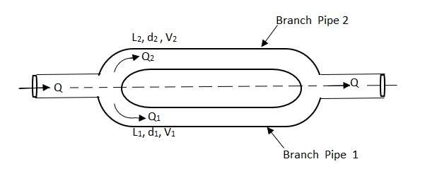
In this arrangement, the loss of head for each branch pipe is same.
Hence, Loss of head for branch pipe 1 = Loss of head of branch pipe 2

Concept of equivalent pipe
L1= length of pipe 1 and d1 = diameter of pipe 1
L2 = length of pipe 2 and d2 = diameter of pipe 2
L3 = length of pipe 3 and d3 = diameter of pipe 3
H = total head loss
L = length of equivalent pipe
d = diameter of equivalent pipe
Total head loss in the compound pipe, neglecting minor losses
 --------- 1
f1 = f2 = f3 = f


Substituting these values in equation 1, we have

 --------- 2
Head loss in the equivalent pipe, 
Where 
 --------- 3
Head loss in compound pipe and in equivalent pipe is same hence equating equations 2 and 3, we have

or 
 --------- 4
Equation 4 is known as Dupuit equation
Consider a pipe AB connected to a high-level storage tank as shown in fig.
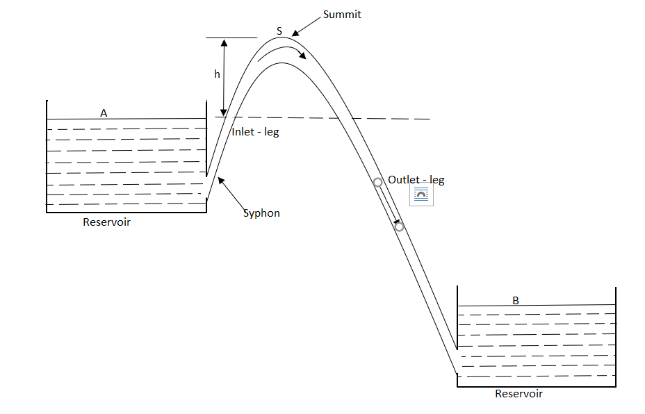
H = Head of water available at the inlet of the pipe, m,
L = Length of the pipe, m,
D = Diameter of the pipe, m,
V = Velocity of water in the pipe, m/s,
f = coefficient of friction, and
hf = Loss of head in the pipe AB, due to friction, m,
WQ = weight of water flowing through the pipe per second = WAV
(Where, Q = discharge of water through the pipe, m3/s)
And, net head water available at B (neglecting minor losses)

Also, the efficiency of transmission,

And power, 


It is evident from above equation that power transmitted depends upon the velocity of water (v), as the other things are constant.
Hence, power Transmitted will be maximum when


It means that power transmitted through the pipe is maximum when head lost due to friction in the pipe is equal to  of the total supply head.
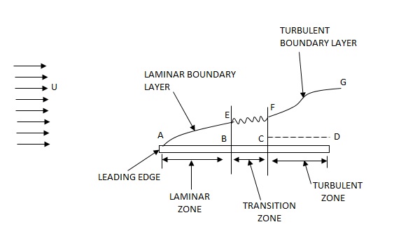
Development of boundary layer on a flat plate Laminar, transitional and turbulent boundary layer
Laminar Boundary Layer
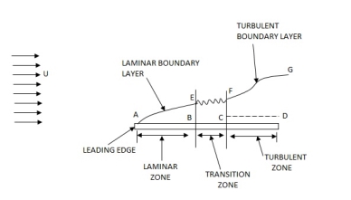
Turbulent Boundary Layer
Boundary Layer Thickness ( )
)

1.  = Thickness of laminar boundary layer,
2.  = Thickness of turbulent boundary layer, and
3.  = Thickness of laminar sublayer.
Displacement Thickness ( )
)


Momentum Thickness (


Energy Thickness ( )
)


Separation of boundary layer
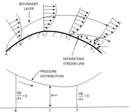
Methods of preventing the separation of boundary layer
The following are the methods of preventing the separation of boundary layer:
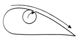
By rotating a circular cylinder lying in a stream of fluid so that the upper side of cylinder where the fluid as well as the cylinder move in the same direction, the boundary layer does not form.

2. Acceleration of fluid in the boundary layer:
This method of controlling separation consists of supplying additional energy to particles of fluid which are being retarded in the boundary layer. This may be achieved either by injecting the fluid into the region of boundary layer from the interior of the body with the help of some available device as shown in the figure or by diverting a portion of fluid of the mainstream from the region of high pressure to the retarded region of boundary layer through a slot provided in the body.

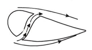
3. Suction of fluid from the boundary layer:
In this method, the slow-moving fluid in the boundary layer is removed by suction through slots or through a porous surface as shown in the figure.
4. Streamlining of the body shapes:
By the use of suitable shaped bodies, the point of transition of the boundary layer from laminar to turbulent can be moved downstream which results in the reduction of the skin friction drag. Furthermore, by streamlining of the body shapes the separation may be eliminated.
5. Supplying additional energy from a blower.
6. Rotating boundary in the direction of flow.
7. Providing small divergence in a diffuser.
8. Providing guide blades in a bend.
9. Providing a trip wire ring in the laminar region for the flow over a sphere.
Drag is the force experienced by an object representing the resistance to its movement through a fluid. Sometimes called wind resistance or fluid resistance, it acts in the opposite direction to the relative motion between the object and the fluid. The example opposite shows the aerodynamic drag forces experienced by an aerofoil or aircraft wing moving through the air with constant angle of attack as the air speed is increased.
The Total Aerodynamic Drag is the sum of the following components:
Induced Drag - Due to the vortices and turbulence resulting from the turning of the air flow and the downwash associated with the generation of lift. Increases with the angle of attack. Inversely proportional to the square of the air speed. Decreases as aircraft speed increases and the angle of attack is reduced. Induced drag associated with the high angle of attack needed to maintain the lift is dominant at low air speeds.
Form Drag or Pressure Drag - Due to the size and shape of the aerofoil. Increases with the square of air speed. Streamlined shapes designed to reduce form drag.
Friction Drag - Arises from the friction of the air against the "skin" of the aerofoil moving through it. Increases with the surface area of the aerofoil and the square of air speed.
Profile Drag or Viscous Drag- The sum of Friction Drag and the Form Drag.
Parasitic Drag or Interference Drag - Incurred by the non-lifting parts of the aircraft such as the wheels, fuselage, tail fins, engines, handles and rivets. Increases with the square of air speed. Parasitic drag becomes dominant at higher air speeds.
Wave Drag - Due to the presence of shock waves occurring on the blade tips of aircraft and projectiles. Associated with passing the sound barrier it is a sudden and dramatic increase in drag which only comes into play as the vehicle increases speed through transonic and supersonic speeds. Independent of viscous effects.
5.10.1 Types of drag
Types of drag:
A Detailed explanation of each type of drag is given below
1. Parasite drag
Parasite drag is a drag produced due to the motion of an object through a fluid. With respect to aviation, the object is an aircraft and the fluid is the atmospheric air. Parasite drag occurs due to air molecules. Parasite drag is classified as form drag or pressure drag, skin friction drag and interference drag.
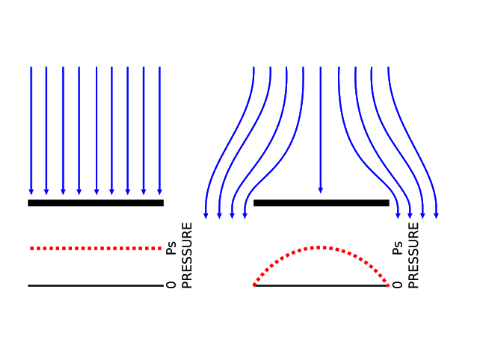
2. Form drag or pressure drag
Form drag - Wikimedia
Form drag is produced due to the shape of the object moving through the fluid. It depends on the cross section of an object. An object with a larger cross section and blunt shape will have a larger form drag whereas an object with a smaller cross section area and a sharper shape will have a lesser form drag.
3. Skin friction drag
Skin friction drag is a drag produced due to friction between an object (aircraft) & fluid (atmospheric air). The rough surface will have high skin friction drag and conversely a smooth surface will have less skin friction drag.
4. Profile drag
Profile drag is a sum of the form drag & skin friction drag.
5. Interference drag
Interference drag is produced due to the interference of two or more airflows having different speeds. And this drag is produced by the interference of different aircraft parts, that is, due to a mixture of airflow around wing and the airflow around the fuselage.
6. Lift Induced drag
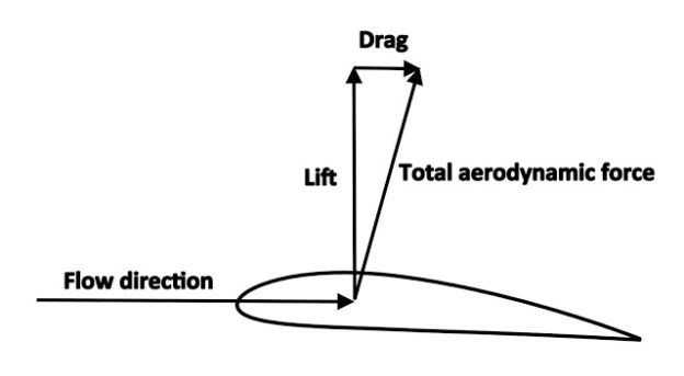
Lift is another aerodynamic force. It is a force which keeps an aircraft in the air and its magnitude is equal to the weight of the aircraft during stable flight. The direction of lift is perpendicular to the oncoming airflow towards the aircraft. Lift induced drag, as the name suggests, is a drag produced due to lift. At slower speed & higher angle of attack, aircraft will have more lift. But as the angle of attack increases, the air pushes the aircraft in the backward direction. This backward push is the induced drag. Technically speaking change in a vector direction of lift of the aircraft results in the formation of this type of drag.
Other types of induced drag are due to a mixture of airflow above and below the wing. The air flow mixes at the tips of the aircraft. We know that speed of airflow above the wing is higher than the speed of an airflow below the wing. Want to know the reason? Check here!
At the wing tips, these two air flows with variable speed, get mixed with each other which produces vortices at wing tips. The Reason for production of vortices is that high-pressure airflow gets pulled toward low-pressure airflow.
8. Wave drag
Wave drag is generally produced at transonic speed (speed almost equals to speed of sound) & Supersonic speed (speed greater than speed of sound). Due to high speed of airflow, shock waves are produced. Shockwaves are nothing but the disturbance in the air. This disturbance increases drag of the aircraft known as wave drag.
Drag Curve
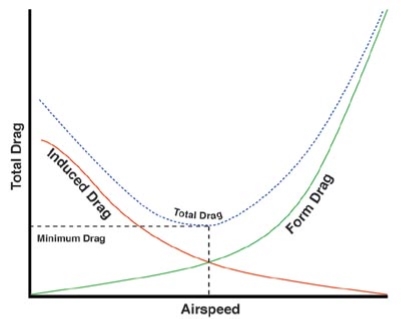
Drag Curve - Wikimedia
This drag curve shows the variation of different types of drag with respect to airspeed.
5.10.2 Drag and lift coefficient
Local coefficient of drag (CD*)
It is defined as the ratio of the shear stress  to the quantity
It is denoted by CD*

Average coefficient of Drag (CD)
It is defined as the ratio of total drag force to the quantity 
It is also called coefficient of drag and is denoted by CD.

where A= area of the surface (or plate)
V = free stream velocity
 = mass density of fluid
Lift Coefficient
Lift coefficient is a dimensionless coefficient giving relationship between the lift generated by a lifting body to fluid density, fluid velocity and the associated reference area. Mathematical representation is as follows:

Where,
CL: lift coefficient
L: lift force
S: relevant surface
q: fluid dynamic pressure
⍴: fluid density
u: flow speed
Definition of Aerofoil
Aerofoil or airfoil is defined as the cross-sectional shape that is designed with curved surface giving it the most favourable ratio between lift and drag in flight. Lift is the component such that the force is perpendicular to the direction of motion and drag is the component parallel to the direction of motion. A similar idea is used in the designing of hydrofoils which is used when water is used as the working fluid.
The designing of the aerofoil depends on the aerodynamic characteristics which further depends on the weight, speed and the purpose of the aircraft. These are dependent on certain terms that need to be defined to understand the design.
Aerofoil Terminology
Following are the terms that are related to aerofoils:
Chord: Chord is defined as the distance between the leading edge which is the point at the front of the aerofoil and has maximum curvature and the trailing edge which is the point at the rear of the aerofoil with maximum curvature along the chord line.
Chord line: Chord line is defined as the straight line connecting the leading and trailing edges.
Upper surface: Upper surface is also known as suction surface which is associated with high velocity and low static pressure.
Lower surface: Lower surface is also known as pressure surface with higher static pressure.
Following are the terms used to describe the behaviour when the aerofoil is moving through a fluid:
Aerodynamic center: The pitching moment is independent of lift coefficient and angle of attack (AOA) at this center.
Center of pressure: The pitching moment is zero at this center.
Angle of attack (AOA): The angle formed between a reference line on a body and the oncoming flow.
Pitching moment: The moment or torque produced the aerodynamic force on the aerofoil.
A bluff body can be defined as a body that, as a result of its shape, has separated flow over a substantial part of its surface. Anybody which when kept in fluid flow, the fluid does not touch the whole boundary of the object. An important feature of a bluff body flow is that there is a very strong interaction between the viscous and inviscid regions.
When the flow separates from the surface and the wake is formed, the pressure recovery is not complete. The larger the wake, the smaller is the pressure recovery and the greater the pressure drag. The art of streamlining a body lies, therefore, in shaping its contour so that separation, and hence the wake, is eliminated, or at least in confining the separation to a small rear part of the body and, thus, keeping the wake as small as possible. Such bodies are known as streamlined bodies. Otherwise, a body is referred to as bluff and a significant pressure drag is associated with it.
Cylinders and spheres are considered bluff bodies because at large Reynolds numbers the drag is dominated by the pressure losses in the wake.
Therefore, when the drag is dominated by a frictional component, the body is called a streamlined body; whereas in the case of dominant pressure drag, the body is called a bluff body.
A body is said to be streamlined if a conscious effort is made to align its shape with the anticipated streamlines in the flow. Streamlined bodies such as race cars and airplanes appear to be contoured and sleek. Otherwise, a body (such as a building) tends to block the flow and is said to be bluff or blunt. Usually, it is much easier to force a streamlined body through a fluid, and thus streamlining has been of great importance in the design of vehicles and airplanes.
A streamlined body is a shape that lowers the friction drag between a fluid, like air and water, and an object moving through that fluid. Drag is a force that slows down motion; friction drag is a special kind of drag.
It occurs when the fluid closest to the object sticks to its surface, exerting a force that opposes the object’s motion.
Many animals, such as birds and dolphins, and many machines, such as airplanes and submarines, have streamlined bodies to reduce friction drag as they move through either air or water.
Numerical:
1. A Fluid of viscosity 8 poise & sp.gr. 1.2 is through a circular pipe of diameter 100mm. The maximum shear stress at the pipe u is z 10 N/M2 Find
(i) The pressure gradient
(ii) The average velocity
(iii) Reynolds number of flows
Given
 = 8 poise= 0.8 N. S/m2
  ,
, 
S = 1.2
 = 1.2 x1000 = 1200 kg/m3
 = 0.1, R = 0.05 m
 = 210 N/m2
1)  o =
o = 
210 =  .
. 
 = -8400 N/m2 per m
2) The average velocity
 =
=  Umax
Umax
=  [
[ R2]
R2]
=  [ -
[ -  ]
]
= 3.28 m/s
3) Reynolds number
Re = =
= 
= 492
2. A Lubricating oil of viscosity 1 poise & sp. gr 0.9 is pumped through a 30mm diameter pipe. If the pressure drop per meter length of pipe is 20KN/m2. Determine
i) The mass flow rate in kg/min
ii) The shear stress at the pipe wall
iii) The Reynold number of flows
iv) The power required per some length of the pipe to maintain the flow
Given,
 = 1 poise = 0.1 N. S/m2
 0.9
0.9
 = 0.9 x 1000 = 900kg/m3
 = 0.03,
 = (P1 – P2) = 20 x
  N.S/m2
(P1 – P2) = 
20 x  =
= 
 = 5.625 m/s
A =  x
x  =
=  x
x = 7.068 X
Q = A.  = 7.068 x
  x 5.625= 3.97 x
  /sec
/sec
Mass flow rate = 
= 900 x 3.97 x  x 60
x 60
= 214.65 kg/min
 =
= 
= 20 x  x
x 
= 150 
Reynolds Number
Re =  =
=  = 1518.7
Loss of head hf =  =
=  =2.265 m
Power =  hf
hf
= (0.9 x 9810 x 3.97 x  x 2.265)
= 79.49 watts
For 50m length power required
P = 79.49 x 50
= 3974.5 watts.
3. A 0.2 m diameter pipe carries liquid in laminar region. A pilot tube placed in the flow at a radial distance of 6 cm from the axis of the pipe indicates velocity of 0.5 m/s. Calculate the maximum velocity, mean velocity & discharge in the pipe.
Given,
D = 0.2 m, R = 0.1 m.
u(6cm) = 0.5 m/s
r = 6 cm = 0.06m
u = -  (
( )
)
0.5 = -  (
( )
)
-  = 78.125
Umax = - 
= 78.125 x 
= 0.7812 m/s
 =
=  Umax=
Umax=  0.7812
= 0.3906 m/s
A =  x
x  =
=  X
X  = 0.0314
Q = A.u
= 0.0314 x 0.3906
= 0.01227  /s
/s
4. Water is flowing over a thin smooth plate of length 4 m and breadth 2m at a velocity of 1.0m/s. If the boundary layer flow changes from laminar to turbulent at a Reynolds number 5× 10⁵. Find
i) the distance from leading edge up to which boundary layer is laminar.
ii) The thickness of the boundary layer at the transition point.
iii) The drag force on one side of the plate
u = 9.81× 10⁻⁴ NS /m2
Soln. L=4m b=2m U=1.0m/s Re = 5×10⁵ u = 9.81×10⁻⁴ Ns/m2
(i) 


(ii) 
(iii) Drag force due to laminar boundary


Drag force due to turbulent boundary layer from F to G.
(FFG)turb = Drag force due to turbulent
boundary layer E to G – Drag force due to turbulent flow from E to F.
=(FEG)turb – (FEF)turb


Drag force on one side of plate = Drag force due to laminar boundary layer up to F + Drag force due to turbulent boundary layer from F to G.
=0.92 + 11.163 = 12.083 N
5. Find the displacement thickness, the momentum thickness and energy thickness for the velocity distribution in the boundary layer given by  , where u is the velocity at a distance y from the plate and u=U at y=
 , where
  is boundary layer thickness. Also calculate the value of
  .
.
Soln. Velocity distribution 
(i) Displacement thickness is given by the equation
 =
=  (Since
 )
)
=  =
=  =
= =
=
(ii) Momentum thickness  is given by the eqn

Substituting the value of  ,
,
 =
= 

(iii) Energy thickness is given by the equation:
 =
= 
= =
=  =
=  -
-  =
= 

6. Find the displacement thickness and energy thickness for the velocity distribution in the boundary layer given by  2
2 .
.
Soln. Velocity distribution  2
2 .
.
(i) Displacement thickness is given by the equation
 =
=  (Since
  )
)


(ii) Momentum thickness  is given by the eqn
 =
= 


(iii)  =
= 
=


7. A jet plane which weighs 29.43kN and having a wing area of 20 flies at a velocity of 950km/hr when the engine delivers 7357.5kW power. 65% of the power is used to overcome the drag resistance of the wing. Calculate the coefficients of lift and drag for the wing. The density of the atmospheric air is 1.21kg/
W=29.43  N
N
A=20
U=950 km/h=950 = 263.88 m/s
P=7357.5  watts
watts
Power used to overcome drag resistance = 65% of 7357.5 
= 7357.5
= 4782.375 watts
watts

Power used to overcome drag resistance = 
4782.375 =
=  236.88
 =18.12
 N
N
 =
=  A
A 
18.12 =
= 
 =0.0215
Force to be lifted = Weight of the plane

 =
=  A
A 
29430=
 =0.0349
8. A plate of 600mm length and 400mm width is immersed in a fluid of sp.gr 0.9 and kinematic viscosity
 . The fluid is moving with a velocity of 6 m/s. Determine
i) Boundary layer thickness
ii) Shear stress at the end of the plate
iii) Drag force on one side of the plate.
L=0.6m
b=0.4m
S=0.9
 =0.9
=0.9  = 900 kg/
U=6 m/s
v=
Reynold Number = 

Therefore, the boundary layer is laminar over the entire length of the plate.
Thickness of boundary layer  where x=0.6
=
Shear stress, 

Drag Force, 


9. A kite 0.8m  0.8m weighing 3.924 N assume angle of
  to the horizontal. The string attached to the kite makes an angle
  to the horizontal. The pull on the string is 24.525N when the wind is flowing at a speed of 30km/h. Find the corresponding coefficient of drag and lift. Density of air is given 1.25kg/
 .
.
Soln. A=0.8  =0.64
=0.64 
W=3.924 N
θ1=120
θ2=450
P=24.525 N
U=30 km/h =
 =1.25 kg/


References:
1. Kundu, Cohen, Dowling, “Fluid Mechanics”, Elsevier India
2. Chaim Gutfinger David Pnueli, “Fluid Mechanics” Cambridge University press.
3. Edward Shaughnessy, Ira Katz James Schaffer, “Introduction to Fluid Mechanics”, Oxford University Press