UNIT 2
Kinematic Analysis of Mechanisms: Analytical Method
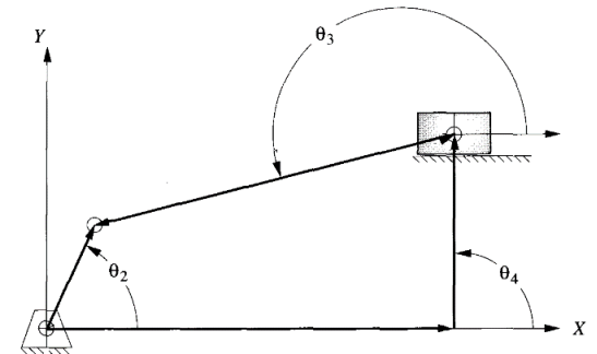
Figure 2.1 Position Analysis of the slider-crank mechanism
Consider the mechanism to possess links named Link one, Link a pair of and Link three, and having link position vectors 𝐫𝟏, 𝐫𝟐, and 𝐫𝟑 having magnitudes r1, r2, and r3 severally. The slider is known as Link four that is connected to the bottom link, i.e., Link 1, through a prismatic joint and is liberal to endure reciprocal motion. Slider Link, four has AN offset from the bottom Link one whose vector is 𝐫𝟒 with magnitude r4. Let the input crank angle be 𝜃2 and also the remainder of the angles square measure shown within the figure. The vector loop equation is given by,
𝒓𝟐+𝒓𝟑=𝒓𝟏+𝒓𝟒 (1)
Equation (1) can be arranged in the components form as
𝑟2cos𝜃2+𝑟3cos𝜃3=𝑟1 (2)
𝑟2sin𝜃2+𝑟3sin𝜃3=𝑟4 (3)
From Equation (3), the orientation of Link 3 can be obtained as
𝜃3=sin−1𝑟4−𝑟2sin𝜃2𝑟3 (4)
The Slider (Link 4) position can be found using Equation (2) as
𝑟3=𝑟1−𝑟2cos𝜃2cos𝜃3 (5)
After calculating 𝜃3 and 𝑟3, an equivalent position diagram can be drawn which is shown in Figure 2.2.
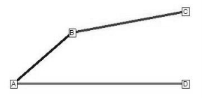
Figure.2.2. Vector diagram for the position of slider-crank mechanism
Key Takeaways:
A position analysis of slider-crank mechanism, calculation of the position in slider-crank mechanism.
𝑣2= 𝜔2 𝑟2 (6)
First draw speed vector 𝐚𝐛⃗⃗⃗⃗⃗ for Link two (Figure 6) traditional to AB (Figure 5) with a magnitude as 𝑣2. Now, draw the rate traditional to 𝐁𝐂⃗⃗⃗⃗⃗ and 𝐃𝐂⃗, severally, so as to get the rate polygonal shape. Note purpose|that time} D is drawn continuously below point C. Magnitudes of 𝐛𝐜⃗⃗⃗⃗ and 𝐝𝐜⃗⃗⃗⃗ area unit up to the linear speed of Link three and Link four, severally. speed vector diagram obtained during this means for a slider-crank mechanism is shown in Figure six. Let the angular speed for Link three be 𝜔3 with its length as 𝑟3 (≡|𝐁𝐂⃗⃗⃗⃗⃗ |). The angular speed is then given by
𝜔3= |𝒃𝒄⃗⃗⃗⃗ |𝑟3 (7)
The linear velocity of Link 4 (slider) can be obtained as
𝑣4=|𝒅𝒄⃗ | (8)
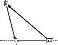
Figure.2.3. Velocity vector diagram for the slider-crank mechanism
ACCELERATION ANALYSIS OF THE SLIDER-CRANK MECHANISM
a2r=w2 r2 (9)
a2t= a2r2 (10)
So the resultant acceleration of Link 2 can be obtained as,
𝑎2=√ ((𝑎2𝑟2)2+ (𝑎2𝑡2)2) (11)
Link 4 (slider) has only linear velocity so it will have only a tangential acceleration component. The radial acceleration component for Link 3 will be:
𝑎3𝑟=𝜔32𝑟3 (12)
The implementation of the acceleration vector diagram is shown in Figure 2.4.
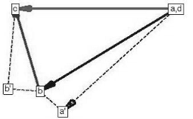
Figure.2.4. Acceleration diagram for the mechanism
First draw speed vector 𝐚𝐛⃗⃗⃗⃗⃗ for Link two (Figure 6) traditional to AB (Figure 5) with a magnitude as 𝑣2. Now, draw the rate traditional to 𝐁𝐂⃗⃗⃗⃗⃗ and 𝐃𝐂⃗, severally, so as to get the rate polygonal shape. Note purpose that time} D is drawn continuously below point C. Magnitudes of 𝐛𝐜⃗⃗⃗⃗ and 𝐝𝐜⃗⃗⃗⃗ area unit up to the linear speed of Link three and Link four, severally. speed vector diagram obtained during this means for a slider-crank mechanism is shown in Figure six. Let the angular speed for Link three be 𝜔3 with its length as 𝑟3 (≡|𝐁𝐂⃗⃗⃗⃗⃗ |). The angular speed is then given by
𝑎3= |𝐛𝐜⃗ | (14)
Key Takeaways:
Velocity analysis, ways of finding out the velocity of slider-crank mechanism,
acceleration analysis, resultant acceleration, velocity, and acceleration diagram.
2.3.1 Velocity and Acceleration by Complex Algebra Method
Using the slider-crank of Fig. 2.6. once more as an illustration with an x-axis along the
the centerline of the guide, and recalling that i^2=-1, we write the complex-number
equations as follows, with the equivalent vector equation below each:
Displacement: ae^i a + be^i
 b+ce^i
 c=x ……. (1)
AB + BD + DC = AC ……(2)
Velocity: iae^ iawAB + (ibe^i
 b + ice^ic) +BC = dx/dt …. (3)
VB +VD/B +VC/D=VC……..(4)
Note that wAB =d a/dt is positive when counter-clockwise and negative when clockwise; in this problem wAB is negative.
The complex conjugate of Eq. (3)

From Eqs. (3) and (4), regarded as simultaneous equations:

The quantities a, b, c square measure obtained from a scale drawing or by trig. Both the vector-polygon and therefore the complex-number ways is without delay extended to accelerations, additionally the} latter also to the upper accelerations.
Differentiating equation 3 we get,

This is equivalent to the vector equation:

Combining the above equation and its complex conjugate, eliminate d^2x/dt^2 and solve for  BC in the following equation for AD:

The higher than complex-number approach conjointly lends itself to the analysis of motions involving Coriolis acceleration. The latter is encountered within the determination of the relative acceleration of 2 outright coincident points on totally different links.
2.3.2 Velocity and Acceleration Analysis by Vector Method
The method is illustrated using a point D on the connecting rod of a slider-crank
mechanism (Fig. 2.5). The vector-velocity equation for C is

Where VB = velocity of B

Where Vc= velocity of C
Vb= velocity of B
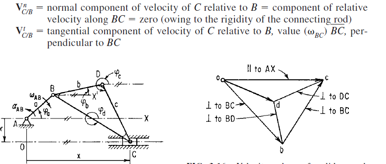
Figure.2.6. Velocity – Vector Diagram
We continue with the slider-crank of Fig. 2.5. After solving for the velocities via the
velocity polygon, write out and “draw” the acceleration equations. Again, proceed in order of increasing difficulty: from B to C to D, and determine first the acceleration of point C:
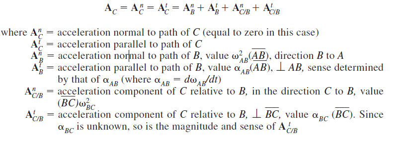
Now, we can draw the acceleration diagram,
1. Choose an arbitrary origin o, as before.
2. Draw each acceleration of scale ka (inch per second squared), and label the appropriate vector terminals with the lowercase letter corresponding
to the point whose acceleration is designated, e.g., AB = (ob)/ka.
Draw ABn, ABt, Ac/B.
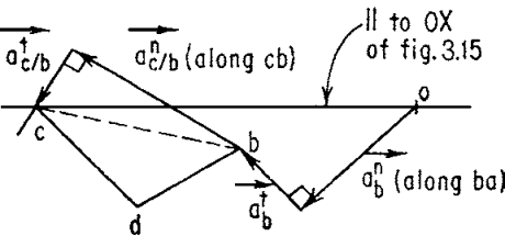
Figure.2.7. Acceleration vector Diagram
Key Takeaways:
Velocity and acceleration analysis of slider-crank chain mechanism by complex
algebra method and vector method, calculation, and analysis, understanding of
concepts.
The sort of machine technique is as giant because of the variety of mechanisms. For specific mechanisms, like cams and gears, specialized codes are on the market. In general, pc codes are capable of analyzing each straightforward and sophisticated mechanism. As way as synthesis is bothered the case is difficult by the nonlinearity of the motion parameters in several mechanisms and by the impossibility of limiting most motions to little displacements. For easier mechanisms, synthesis codes are on the market. For a lot of advanced mechanisms parameter variation of study codes or heuristic, ways are in all probability the foremost powerful presently on the market tools. the topic remains underneath intensive development, particularly with reference to interactive lighting tricks [for example, CADSPAM, software of spatial mechanisms. At high speeds, the inertia forces related to the moving links cause shaking forces and moments to be transmitted to the frame. equalization will cut back or eliminate these. Three-dimensional mechanisms also are referred to as “spatial mechanisms.” Points on these mechanisms travel three-dimensional curves. the fundamental three- dimensional mechanisms are the “spherical four-bar mechanisms” (Fig. 2.8) and therefore the “offset” or “spatial four-bar mechanism” (Fig. 2.9.). The spherical four-bar mechanism of Fig. 2.9. consists of links AB, BC, CD, and DA, every on a good circle of the sphere with center O; turning joints at A, B, C, and D, whose axes meet at O; lengths of links measured by great-circle arcs or angles atomic number 83 subtended at O. Input _2, output _1; the single degree of freedom, though. Figure 2.9. shows a spatial four-bar mechanism; turning joint at D, turn-slide (also referred to as cylindrical) joints at B, C, and D; aij denote minimum distances between axes of joints; input = two at D; output at A consists of translation s and rotation ø1; Σfi=7; freedom, F = 1. Three-dimensional mechanisms utilized in apply are typically special cases of the above 2 mechanisms. Among these are Hooke’s joint,

is further explained in other units.
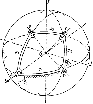
Figure.2.8. Spherical four-bar Mechanism
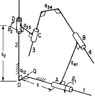
Figure.2.9. Spatial or four-bar Mechanism
Key Takeaways:
Computer-aided analysis of slider-crank and four-bar mechanism, Spherical four-bar mechanism, spatial or four-bar mechanism. Analysis with the help of designing
software.

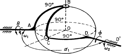
Figure.2.10 Hooke’s Joint
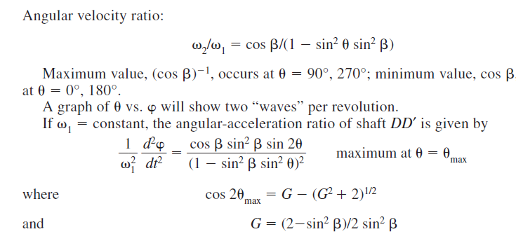
Key Takeaways:
Analysis of Hooke’s joint, calculation of angular velocity ratio, and its types.
Reference Books:
2. Bevan T, “Theory of Machines”, Third Edition, Longman Publication |
|
3. Paul E. Sandin, “Robot Mechanisms and Mechanical Devices Illustrated”, Tata McGraw Hill Publication
|
4. Ghosh Malik, “Theory of Mechanism and Machines”, East-West Pvt. Ltd.
|
5. M.P. Groover, “Automation, production systems, and computer-integrated manufacturing”, Prentice-Hall of India Pvt. Ltd